1
TECHNICAL MANU
AL
MANUAL
*CVM96 & *MVM96
40" 96% Gas Furnace
• Refer to Service Manual RS6612001 for installation, operation, and troubleshooting information.
• All safety information must be followed as provided in the Service Manual.
• Refer to the appropriate Parts Catalog for part number information.
• Model numbers listed on page 3.
®
C
US
This manual is to be used by qualified, professionally trained HVAC technicians only.
Goodman does not assume any responsibility for property damage or personal
injury due to improper service procedures or services performed by an unqualified
person.
Copyright © 2011 Goodman Manufacturing Company, L.P.
RT6612023
June 2011
2
V
FURNACE TYPE
V: Two Stage/
Variable-Speed
M
M
060
3
B
X
A
A
MINOR
REVISION
A: Initial Release
MAJOR
REVISION
A: Initial Release
ADDITIONAL
FEATURES
N: Natural Gas
X: Low NOx
CABINET
WIDTH
B: 17-1/2"
C: 21"
D: 24-1/2"
AIRFLOW
CAPABILITY
@ 0.5" ESP
3: 1200
4: 1600
5: 2000
NOMINAL INPUT
060: 60,000 Btuh
080: 80,000 Btuh
100: 100,000 Btuh
115: 115,000 Btuh
AFUE
96: 96%
96
COMMUNICATION FEATURE
M: Modulating Furnace
4-Wire Communication Ready
SUPPLY TYPE
M: Upflow/Horizontal
C: Downflow/Horizontal
PRODUCT
TYPE:
G: Goodman
®
A: Amana
Brand
G
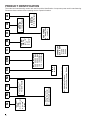
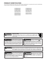
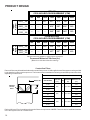
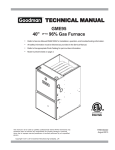
PRODUCT IDENTIFICATION
The model and manufacturing number are used for positive identification of component parts used in manufacturing.
Please use these numbers when requesting service or parts information.
PRODUCT IDENTIFICATION
The model and manufacturing number are used for positive identification of component parts used in manufacturing.
Please use these numbers when requesting service or parts information.
GCVM960604CXA*
GCVM960805DXA*
GCVM961005DXA*
GMVM960603BXA*
GMVM960805CXA*
GMVM961005DXA*
GMVM961155DXA*
WARNING
HIGH VOLTAGE!
Disconnect ALL power before servicing or installing this unit. Multiple power
sources may be present. Failure to do so may cause property damage, personal
injury or death.
Goodman will not be responsible
for any injury or property damage
arising from improper service or service procedures. If
you install or perform service on this unit, you assume
responsibility for any personal injury or property damage
which may result. Many jurisdictions require a license to
install or service heating and air conditioning equipment.
WARNING
WARNING
Installation and repair of this unit
should be performed ONLY by
individuals meeting the requirements of an "entry level technician", at a minimum, as
specified by the Air-Conditioning, Heating, and Refrigeration Institute (AHRI). Attempting to install or repair this
unit without such background may result in product
damage, personal injury or death.
WARNING
The United States Environmental Protection Agency (“EPA”) has issued various regulations regarding the introduction and disposal of refrigerants introduced into this unit. Failure to follow
these regulations may harm the environment and can lead to the imposition of substantial fines.
These regulations may vary by jurisdiction. Should questions arise, contact your local EPA office.
Do not connect or use any device
that is not design certified by
Goodman for use with this unit.
Serious property damage, personal injury, reduced unit
performance and/or hazardous conditions may result
from the use of such non-approved devices.
WARNING
ACVM960604CXA*
ACVM960805DXA*
AMVM960603BXA*
AMVM960805CXA*
AMVM961005DXA*
AMVM961155DXA*
To prevent the risk of property
damage, personal injury, or death,
do not store combustible materials or use gasoline or
other flammable liquids or vapors in the vicinity of this
appliance.
WARNING
3
PRODUCT DESIGN
General Operation
Notes:
Models covered by this manual come with a new 4-wire
communicating PCB. When paired with a compatible
communicating indoor unit and a CTK0*AA communicating
thermostat, these models can support 4-wire communication
protocol and provide more troubleshooting information. These
models are also backward compatible with the noncommunicating thermostat wiring.
The *CVM96 and *MVM96 furnaces are equipped with an
electronic ignition device used to light the burners and an
induced draft blower to exhaust combustion products.
1. Installer must supply one or two PVC pipes: one for combustion air (optional) and one for the flue outlet (required).
Vent pipe must be either 2” or 3” in diameter, depending
upon furnace input, number of elbows, length of run and
installation (1 or 2 pipes). The optional Combustion Air
Pipe is dependent on installation/code requirements and
must be 2” or 3” diameter PVC.
An interlock switch prevents furnace operation if the blower
door is not in place. Keep the blower access door in place
except for inspection and maintenance.
3. Conversion kits for propane gas operation are available.
This furnace is also equipped with a self-diagnosing electronic control module. In the event a furnace component is
not operating properly, the control module LED will flash on
and off in a factory-programmed sequence, depending on
the problem encountered. This light can be viewed through
the observation window in the blower access door. Refer to
the Troubleshooting Chart for further explanation of the LED
codes and Abnormal Operation - Integrated Ignition Control
section in the Service Instructions for an explanation of the
possible problem.
The rated heating capacity of the furnace should be greater
than or equal to the total heat loss of the area to be heated.
The total heat loss should be calculated by an approved
method or in accordance with “ASHRAE Guide” or “Manual
J-Load Calculations” published by the Air Conditioning Contractors of America.
*Obtain from: American National Standards Institute 1430
Broadway New York, NY 10018
Location Considerations
•
•
•
The furnace should be as centralized as is practical
with respect to the air distribution system.
4. Installer must supply the following gas line fittings, depending on which entrance is used:
Left -- Two 90º Elbows, one close nipple and one 2.5"
nipple, straight pipe.
Right -- Straight pipe to reach gas valve.
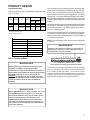
Accessibility Clearances (Minimum)
*MVM96* MINIMUM CLEARANCES TO COMBUSTIBLE MATERIALS
(INCHES)
POSITION* FRONT
SIDES
REAR
TOP
FLUE
FLOOR
Upflow
3
0
0
1
0
C
Horizontal
Alcove
6
0
4
0
C
*=
All positioning is determined as installed unit is viewed from the front.
C= If placed on combustible floor, floor MUST be wood only.
NC= For instalaltion on non-combustible floors only. A combustible
subbase must be used for installations on combustible flooring.
*CVM96 MINIMUM CLEARANCES TO COMBUSTIBLE MATERIALS
(INCHES)
POSITION* FRONT
SIDES
REAR
TOP
FLUE
FLOOR
Upflow
1
0
0
1
0
NC
Horizontal
Alcove
6
0
4
0
C
Do not install the furnace directly on carpeting, tile, or
combustible material other than wood flooring.
*=
When suspending the furnace from rafters or joists,
use 3/8" threaded rod and 2” x 2” x 3/8” angle as
shown in the Installation and Service Instructions. The
length of the rod will depend on the application and
clearance necessary.
Alcove Illustration
REAR
SIDE
When installed in a residential garage, the furnace
must be positioned so the burners and ignition source
are located not less than 18 inches (457 mm) above
the floor and protected from physical damage by vehicles.
All positioning is determined as installed unit is viewed from the front.
C= If placed on combustible floor, floor MUST be wood only.
NC= For instalaltion on non-combustible floors only. A combustible
subbase must be used for installations on combustible flooring.
SIDE
•
2. Line voltage wiring can enter through the right or left side
of the furnace. Low voltage wiring can enter through the
right or left side of furnace.
ALCOVE
24" at front is required for servicing or cleaning.
Note: In all cases accessibility clearance shall take precedence over clearances from the enclosure where accessibility clearances are greater. All dimensions are given in inches.
4
PRODUCT DESIGN
High Altitude Derate
Altitude certification of the *CVM96 and *MVM96 furnaces
is up to 10,000 ft.
Gas
Altitude
Natural
Kit
Orifice
None
#45 1
Manifold Pressur e Pressure
Switch
High
Low
Change
Stage
Stage
0-10,000
Propane
LPKMOD** *** 1.25MM 2
3.5" w.c .
1" w.c.
None
10.0"
w.c.
2.6" w.c .
None
NOTE: In Canada, gas furnaces are only certified to 4500 feet.
Except 115,000 BT U: #43
1
2
Except 115,000 BT U: #55
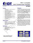
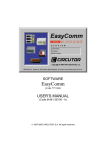
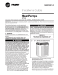
As a two-stage non-communicating furnace, the furnace integrated control module provides terminals for both “W1” and “W2”,
and “Y1” and “Y2” thermostat connections. This allows the furnace to support the following system applications: ‘Two-Stage
Heating Only’, ‘Two-Stage Heating with Single Stage Cooling’,
and ‘Two-Stage Heating with Two-Stage Cooling’. Refer to the
following figures for proper connections to the integrated control
module.
Low voltage connections can be made through either the right or
left side panel. Thermostat wiring entrance holes are located in
the blower compartment. The following figure shows connections for a “heat/cool system”.
This furnace is equipped with a 40 VA transformer to facilitate
use with most cooling equipment. Consult the wiring diagram,
located on the blower compartment door, for further details of
115 Volt and 24 Volt wiring.
Furnace Model
LP Kit
A/GMVM960603BX
LPKMOD060UF
A/GMVM960805CX
LPKMOD080UF
A/GMVM961005DX
LPKMOD100UF
IMPORTANT NOTE
A/GMVM961155DX
LPKMOD115UF
A/GCVM960604CX
LPKMOD060CF
THERMOSTAT “R” REQUIRED IF OUTDOOR UNIT IS EQUIPPED WITH A COMFORT ALERT™ MODULE OR IF THE OUTDOOR UNIT IS A PART OF THE COMFORTNET™ FAMILY OF EQUIPMENT.
LPKMOD080CF
GCVM961005DX
LPKMOD100CF
O
Y2
Y1
W2
W1
G
C
R
2
1
24 VOLT THERMOSTAT WIRING
24 V THERMOSTAT CONNECTIONS
IMPORTANT NOTE
WIRE ROUTING MUST NOT INTERFERE WITH CIRCULATOR BLOWER OPERATION, FILTER REMOVAL OR ROUTINE MAINTENANCE.
A REMOVABLE PLUG CONNECTOR IS PROVIDED WITH THE CONTROL TO MAKE THERMOSTAT WIRE CONNECTIONS. THIS PLUG MAY BE REMOVED, WIRE CONNECTIONS MADE TO THE PLUG, AND REPLACED. IT IS STRONGLY RECOMMENDED THAT MULTIPLE WIRES INTO A SINGLE TERMINAL BE TWISTED TOGETHER PRIOR TO INSERTING INTO THE PLUG CONNECTOR. FAILURE TO DO SO MAY RESULT IN INTERMITTENT OPERATION.
DEHUM
A/GCVM960805DX
NOTE: Use of ramping profiles requires a jumper between
Y1 and O.
AUX
Low Voltage Connections with Auxiliary Terminals
The auxiliary contacts are shipped with a factory installed
jumper. As an option, the auxiliary contacts may be wired
to a normally closed float switch. In the event of open
contacts, the furnace will be disabled until the condition is
corrected. These are 24 volt terminals fed internally, do not
apply another voltage source to these terminals.
IMPORTANT NOTE
DIP SWITCH #13 MUST BE SET TO MATCH THERMOSTAT TYPE. TO USE THE CTK01AA COMMUNICATING THERMOSTAT, DIP SWITCH #13 MUST BE SET TO ON POSITION. THIS IS ALSO THE CORRECT SETTING FOR A NON‐COMMUNICATING 2‐STAGE THERMOSTAT. TO USE CTK02AA MODULATING THERMOSTAT, CHECK TO MAKE SURE DIP SWITCH #13 IS IN THE OFF POSITION (FACTORY POSITION). THIS IS ALSO THE CORRECT POSITION WHEN USING A NON‐COMMUNICATING SINGLE‐STAGE THERMOSTAT.
5
PRODUCT DESIGN
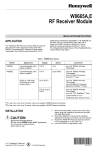
Thermostat
R
Furnace Integrated
Control Module
R
NEU
Y
C
Dehumidistat
[Optional]
Remote
Condensing Unit
(Single-Stage Cooling)
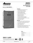
Thermostat - Single-Stage Heating with Single-Stage Cooling
IMPORTANT NOTE
TO APPLY A SINGLE‐STAGE HEATING THERMOSTAT, THE THERMOSTAT SELECTOR SWITCH ON THE INTEGRATED CONTROL MODULE MUST BE SET ON SINGLE‐STAGE.
_____________________________________
R
Furnace Integrated
Control Module
R
Y
C
Remote
Condensing Unit
(Single-Stage Cooling)
NEU
Dehumidistat
[Optional]
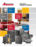
Thermostat - Two-Stage Heating with Single-Stage Cooling
6
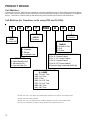
The modulating line of furnaces may be operated with
CTK0*AA communicating thermostats or with a single or 2
stage non-communicating thermostat. Dip switch #13 must
be checked and set for proper orientation regardless of the
thermostat chosen. Factory setting is ON position which is
correct for a CTK02AA or single stage heating thermostat.
To use a CTK01AA or a 2 stage thermostat; switch #13
must be turned to the off position.
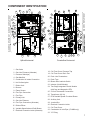
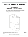
COMPONENT IDENTIFICATION
8
7
5
23
26
27
10
7
10
*
2
24
33
*
*
13
15
*
*
1
*
*
18
19
19
28
33
14
16 17
18
31
11
25
3
12
3
*
BLOWER COMPARTMENT
11
*
BURNER COMPARTMENT
32
4
20
3
3
15
31
17
29
20
21
14
BLOWER COMPARTMENT
5
9
6
16
30
18
18
19
20
19
20
28
13
12
2 21
23
26
27
25
Upflow/Horizontal
9
7
8
7 6 4
1
Counterflow /Horizontal
1 Gas Valve
2 Gas Line Entrance (Alternate)
3 Pressure Switch(es)
4 Gas Manifold
5 Combustion Air Intake Connection
6 Hot Surface Igniter
7 Rollout Limit
8 Burners
9 Flame Sensor
10 Flue Pipe Connection
11 Flue Pipe
12 Primary Limit
13 Gas Line Entrance
14 Flue Pipe Connection (Alternate)
15 Rubber Elbow
16 Variable-Speed Induced Draft Blower
17 Electrical Connection Inlets (Alternate)
18 Coil Front Cover Pressure Tap
19 Coil Front Cover Drain Port
20 Drain Line Penetrations
21 Drain Trap
22 Blower Door Interlock Switch
23 Inductor (Not All Models)
24 Two-Stage Integrated Control Module
(with fuse and diagnostic LED)
25 24 Volt Thermostat Connections
26 Transformer (40 VA)
27 ECM Variable Speed Circulator Blower
28 Auxiliary Limit
29 Junction Box
30 Electrical Connection Inlets
31 Coil Front Cover
32 Combustion Air Inlet Pipe (*CVM96 only)
33 "H" Fitting
7
8
LEFT SIDE
VIEW
23 9/16
BOTTOM KNOCK-OUT
1 3/4
2 5/8
30 1/4
C
21
24 1/2
0603BX*
0805CX*
1005DX*
1155DX*
SMALL
MEDIUM
LARGE
17 1/2
UNITS
A
20 3/8
16 3/8
12 3/8
C
2
D
32 13/16
18 5/8
14 5/8
12 5/8
CONDENSATE
DRAIN TRAP
w/ 3/4" PVC
DISCHARGE
(RIGHT OR
LEFT SIDE)
19 3/16
4 1/8
2 11/16
VENT/FLUE PIPE
2" PVC
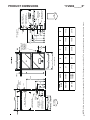
All dimensions are in inches.
23
19
15
B
BOTTOM KNOCK-OUT
CABINET
SIZE
11 3/4
19 3/16
DRAIN
TRAP
AIR INTAKE
PIPE
2" PVC
B
(DISCHARGE AIR)
A
1 3/4
RIGHT SIDE
DRAIN LINE
HOLES
STANDARD GAS
SUPPLY HOLE
AIR
DISCHARGE
RIGHT SIDE
VIEW
SIDE CUT-OUT
HIGH VOLTAGE
ELECTRICAL HOLE
LOW VOLTAGE
ELECTRICAL HOLE
DRAIN
TRAP
NOTE: Airflow area will be reduced by approximately 18% if duct flanges are not unfolded. This could cause performance issues and noise issues.
1 1/2
1 5/8
SIDE CUT-OUT
HIGH VOLTAGE
ELECTRICAL HOLE
LOW VOLTAGE
ELECTRICAL HOLE
LEFT SIDE
DRAIN LINE
HOLES
19 3/4
AIR
DISCHARGE
PRODUCT DIMENSIONS
*MVM96_____XA*
21
24 1/2
0604CX*
0805DX*
1005DX*
MEDIUM
LARGE
A
UNITS
23
19
B
DISCHARGE AIR
E
FOLDED FLANGES
UNFOLDED FLANGES
CABINET
SIZE
9 13/16
11 1/2
15 1/2
28 5/16
20 3/8
16 3/8
C
2
18 5/8
14 5/8
14
18 13/16
D
28 5/16
CONDENSATE
DRAIN TRAP
w/ 3/4" PVC
DISCHARGE
(RIGHT OR
LEFT SIDE)
20 7/8
17 1/2
E
2 11/16
1 3/4
VENT/FLUE PIPE
2" PVC
7 3/8
RIGHT SIDE
DRAIN LINE
HOLES
AIR
DISCHARGE
ALTERNATE GAS
SUPPLY HOLE
DRAIN
TRAP
HIGH VOLTAGE
ELECTRICAL HOLE
LOW VOLTAGE
ELECTRICAL HOLE
NOTE: Airflow area will be reduced by approximately 18% if duct flanges are not unfolded. This could cause performance issues and noise issues.
AIR
DISCHARGE
20 5/32
FOLDED FLANGES
18 5/8
UNFOLDED FLANGES
STANDARD GAS
SUPPLY HOLE
LEFT SIDE
DRAIN LINE
HOLES
DRAIN
TRAP 2 5/8
HIGH VOLTAGE
ELECTRICAL HOLE
LOW VOLTAGE
ELECTRICAL HOLE
1 3/4
AIR INTAKE
PIPE
2" PVC
A
B
(RETURN AIR)
C
PRODUCT DIMENSIONS
*CVM96_____X*
9
10
-0.96
-0.85
-1.01
-1.01
-0.96
-0.85
A/GMVM960805CX
A/GMVM961005DX
A/GMVM961155DX
A/GCVM960604CX
A/GCVM960805DX
GCVM961005DX
-0.70
-0.81
-0.86
-0.86
-0.70
-0.81
-0.81
-0.25
-0.25
-0.25
-0.25
-0.25
-0.25
-0.25
-0.10
-0.10
-0.10
-0.10
-0.10
-0.10
-0.10
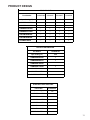
(2) Data given is the least negative pressure required for pressure switch to remain closed.
-0.10
-0.10
-0.10
-0.10
-0.10
-0.10
-0.10
0130F00070
0130F00070
0130F00070
20197308
20197308
20197308
20197308
-0.70
-0.81
-0.86
-0.86
-0.70
-0.81
-0.81
0130F00154
0130F00155
0130F00156
0130F00156
0130F00154
0130F00155
0130F00155
NEGATIVE
PRESSURE SWITCH TRIP POINTS AND USAGE
PRESSURE
COIL COVER
WITH FLUE
FIRING
TRIP POINT COIL COVER TRIP POINT ID BLOWER
TYPICAL
PRESSURE
COIL COVER PRESSURE ID BLOWER
SEA
PRESSURE
SWITCH
PRESSURE
SWITCH
LEVE
SWITCH
PART
#
SWITCH
PART #
(2)
DATA
(1) Data given is least negative pressure required for pressure switch to close.
-0.96
A/GMVM960603BX
MODEL
NEGATIVE
NEGATIVE NEGATIVE
PRESSURE PRESSURE PRESSURE
ID BLOWER ID BLOWER COIL COVER
WITH FLUE WITH FLUE WITH FLUE
NOT FIRING
FIRING
NOT FIRING
TYPICAL
TYPICAL
TYPICAL
SEA
SEA
SEA
LEVEL
LEVE
LEVEL
( 1)
(2 )
(1)
DATA
DATA
DATA
PRESSURE SWITCH TRIP POINTS AND USAGE CHART
PRODUCT DESIGN
PRODUCT DESIGN
PRIMARY LIMIT
Part Number
0130M00063
20162905
20162907
20162903
Open Setting (°F)
140
145
155
160
A/GMVM960603BX
1
---
---
---
A/GMVM960805CX
---
1
---
---
A/GMVM961005DX
---
1
---
---
A/GMVM961155DX
---
---
1
---
A/GCVM960604CX
---
---
1
---
A/GCVM960805DX
---
1
---
---
GCVM961005DX
---
---
---
1
ROLLOUT LIMIT SWITCHES
Part Number
0130F00123
Open Setting (°F)
250
A/GMVM960603BX
2
A/GMVM960805CX
2
A/GMVM961005DX
2
A/GMVM961155DX
2
A/GCVM960604CX
2
A/GCVM960805DX
2
GCVM961005DX
2
AUXILIARY LIMIT SWITCHES
Part Number
0130F00038
Open Setting (°F)
120
A/GMVM960603BX
1
A/GMVM960805CX
1
A/GMVM961005DX
1
A/GMVM961155DX
1
A/GCVM960604CX
1
A/GCVM960805DX
1
GCVM961005DX
1
11
PRODUCT DESIGN
Coil Matches:
A large array of Amana® brand coils are available for use with the GMH95 furnaces, in either upflow or horizontal applications. These coils are available in both cased and uncased models (with the option of a field installed TXV expansion
device). These 95%+ furnaces match up with the existing Amana® brand coils as shown in the chart below.
Coil Matches (for Goodman® units using R22 and R-410A):
C
A
P
F
1824
A
6
EXPANSION
DEVICE:
F: Flowrater
PRODUCT
TYPE:
C: Indoor Coil
CABINET FINISH:
U: Unpainted
P: Painted
N: Unpainted Case
APPLICATION
A: Upflow/Downflow Coil
H: Horizontal A Coil
S: Horizontal Slab Coil
A
REVISION
A: Revision
REFRIGERANT
CHARGE:
6: R-410A or R-22
2: R-22
4: R-410a
NOMINAL WIDTH FOR GAS FURNACE
A: Fits 14" Furnace Cabinet
B: Fits 17 1/2" Furnace Cabinet
C: Fits 21" Furnace Cabinet
D: Fits 24 1/2" Furnace Cabinet
N: Does Not Apply (Horizontal Slab Coils)
NOMINAL CAPACITY RANGE
@ 13 SEER
1824: 1 1/2 to 2 Tons
3030: 2 1/2 Tons
3636: 3 Tons
3642: 3 to 3 1/2 Tons
3743: 3 to 3 1/2 Tons
4860: 4 & 5 Tons
4961: 4 & 5 Tons
• All CAPF coils in B, C, & D widths have insulated blank off plates for use with one size smaller furnaces.
• All CAPF coils have a CAUF equivalent.
• All CHPF coils in B, C & D heights have an insulated Z bracket for use with one size smaller furnace.
• All proper coil combinations are subject to being ARI rated with a matched outdoor unit.
12
PRODUCT DESIGN
Thermostats:
NOTE: Complete lineup of thermostats can be found in the Thermostat Specification Sheets.
Filters:
Filters are required with this furnace and must be provided by the installer. The filters used must comply with UL900 or
CAN/ULCS111 standards. Installing this furnace without filters will void the unit warranty.
Upflow Filters
This furnace has provisions for the installation of return air filters at the side and/or bottom return. The furnace will
accommodate the following filter sizes depending on cabinet size:
(1)
SIDE RETURN
Approx.
Cabinet
Nominal
Flow
Area
Width
Filter Size
2
(in.)
(in.)
(in )
All
16 x 25 x 1
400
BOTTOM RETURN
Approx.
Cabinet
Nominal
Flow
Area
Width
Filter Size
2
(in.)
(in.)
(in )
17-1/2
14 x 25 x 1
350
21
16 x 25 x 1
400
24-1/2
20 x 25 x 1
500
(1) Flanges on bottom return must be unfolded
Refer to Minimum Filter Area tables to determine filter area requirement. NOTE: Filters can also be installed elsewhere in
the duct system such as a central return.
Input
Airflow
UPFLOW
COOLING AIRFLOW REQUIREMENT (CFM)
600
800
1000
1200
1400
1600
2000
0603__XA
---
---
564*
564*
672
768
0805__XA
---
---
---
752*
752*
768
960
1005__XA
1155__XA
---
---
---
940*
940*
940*
960
Input
Airflow
COUNTERFLOW
COOLING AIRFLOW REQUIREMENT (CFM)
600
800
1000
1200
1400
1600
2000
0604__XA
---
---
641*
641*
672
768
---
0805__XA
1005__XA
---
---
---
854*
854*
854*
960
*Minimum filter area dictated by heating airflow requirement.
Disposable Minimum Filter Area (in2)
[Based on a 300 ft/min filter face velocity]
13
PRODUCT DESIGN
Input
Airflow
UPFLOW
COOLING AIRFLOW REQUIREMENT (CFM)
600
800
1000
1200
1400
1600
2000
0603__XA
---
---
627*
627*
672
768
---
0805__XA
---
---
---
836*
836*
836*
960
1005__XA
1155__XA
---
---
---
940*
940*
940*
960
Input
Airflow
COUNTERFLOW
COOLING AIRFLOW REQUIREMENT (CFM)
600
800
1000
1200
1400
1600
2000
0604__XA
---
---
320*
320*
336
384
---
0805__XA
1005__XA
---
---
---
427*
427*
427*
480
*Minimum filter area dictated by heating airflow requirement.
Permanent Minimum Filter Area (in2)
[Based on a 600 ft/min filter face velocity]
Counterflow Filters
Return air filters may be installated at the at the counterflow top return. A field supplied center filter support must be provided
by the installer in order to use the top return. The furnace will accommodate the following counterflow top return filter sizes
depending on cabinet size:
Counterflow Top Return
Return Air
Cabinet Width
Filter Area
2
Qty
(in )
Optional
Access
Door
Filter Size Dimension "A"
(in)
(in)
17 1/2
"A"
Min
21
14.2
600
2
15 X 20 X 1
24 1/2
11.3
17 1/2
21
19.7
800
2
20 X 20 X 1
24 1/2
24 1/2
18.8
17.7
17 1/2
21
13.0
25.0
1000
2
25 X 20 X 1
24.3
23.4
Refer to Minimum Filter Area tables to determine filter area requirement. NOTE: Filters can also be installed elsewhere
in the duct system such as a central return.
14
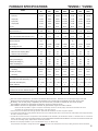
FURNACE SPECIFICATIONS
*MVM96 / *CVM96
*MVM960603B *MVM960805 *MVM961005 *MVM96115 *CVM960604 *CVM960805 GCVM96100
XA*
CXA*
DXA*
5DXA*
CXA*
DXA*
5DXA*
MODEL
Btuh
Input (US)
60,000
80,000
100,000
115,000
60,000
80,000
100,000
Output (US)
57,600
76,800
96,000
109,250
57,600
76,800
96,000
Input (CAN)
60,000
80,000
100,000
115,000
60,000
80,000
100,000
Output (CAN)
57,600
76,800
96,000
109,250
57,600
76,800
96,000
96.0%
96.0%
96.0%
95.0%
96.0%
96.0%
95.0%
A.F.U.E.
Rated External Static (" w.c.)
.20 - .50
.20 - .50
.20 - .50
.20 - .50
.20 - .50
.20 - .50
.20 - .50
Temperature Rise (°F)
20-50
35-65
35 - 65
35-65
20-50
20-50
25-55
ID Blower Pressure Switch Trip Point (" w.c.)
-0.81
-0.81
-0.70
-0.86
-0.86
-0.81
-0.70
Front Cover Pressure Switch Trip Point (" w.c.)
-0.10
-0.10
-0.10
-0.10
-0.10
-0.10
-0.10
Blower Wheel (D" x W")
10 x 8
11 x 10
11 x 10
11 x 10
10 x 10
11 x 10
11 x 10
Blower Horsepower
3/4
Blower Speeds
Max CFM @ 0.5 E.S.P.
Power Supply
Minimum Circuit Ampacity (MCA)
Maximum Overcurrent Device
( 1)
(2)
1
1
1
3/4
1
1
Variable
Variable
Variable
Variable
Variable
Variable
Variable
1400
2200
2200
2200
1760
2200
2200
115-60-1
115-60-1
115-60-1
115-60-1
115-60-1
115-60-1
115-60-1
6.0
14.2
14.2
14.2
6.0
14.2
14.2
15.0
15.0
15.0
15.0
15.0
15.0
15.0
Transformer (VA)
40
40
40
40
40
40
40
Primary Limit Setting (°F)
140
145
145
155
155
145
160
Auxiliary Limit Setting (°F)
120
120
120
120
120
120
120
Rollout Limit Setting (°F)
250
250
250
250
250
250
250
30 secs.
30 secs.
30 secs.
30 secs.
30 secs.
30 secs.
30 secs.
150 secs.
150 secs.
150 secs.
150 secs.
150 secs.
150 secs.
150 secs.
Fan Delay On Heating
Off Heating
(3)
Fan Delay On Cooling
Off Cooling
Gas Supply Pressure (Natural/Propane) ("w.c.)
Manifold Pressure (Natural/Propane) ("w.c.)
Orifice Size (Natural/Propane)
Number of Burners
Vent Connector Diameter (inches)
(4)
Combustion Air Connector Diameter (inches)
Shipping Weight (lbs.)
(5)
6 sec.
6 sec.
6 sec.
6 sec.
6 sec.
6 sec.
6 sec.
45 secs.
45 secs.
45 secs.
45 secs.
45 secs.
45 secs.
45 secs.
7 / 11
7 / 11
7 / 11
7 / 11
7 / 11
7 / 11
7 / 11
3.5 / 10
3.5 / 10
3.5 / 10
3.5 / 10
3.5 / 10
3.5 / 10
3.5 / 10
45 / 1.25mm
45 / 1.25mm
45 / 1.25mm
43 / 55
45 / 1.25mm
45 / 1.25mm
45 / 1.25mm
3
4
5
5
3
4
5
2
3
3
3
2
3
3
2
2
2
2
2
2
2
135
145
170
170
139
165
170
(1)
Wire size should be determined in accordance with National Electrical Codes. Extensive wire runs will require larger wire sizes.
Maximum Overcurrent Protection Device: May use Time Delay Fuse or HACR type Circuit Breaker of the same size as noted.
(3)
Off Heating - this fan delay timing is adjustable (100 and 150 seconds). Furnaces are shipped with 150 second off delay.
(4)
See Installation Instructions for appropriate vent diameter, length and number of elbows.
(5)
See Installation Instructions for appropriate combustion air pipe diameter, length and number of elbows.
(2)
NOTE: This data is provided as a guide, it is important to electrically connect the unit and properly size fuses/circuit breakers and wires in
accordance with all national and/or local electrical codes. Use copper wire only.
1. These furnaces are manufactured for natural gas operation. Optional kits are available for conversion to propane operation.
2. For elevations above 2000 feet the rating should be reduced by 4% for each 1000 feet above sea level. The furnace must not be derated, orifice changes should only
be made if necessary for altitude.
3. The total heat loss from the structure as expressed in TOTAL BTU/HR must be calculated by the manufacturers method or in accordance with the "A.S.H.R.A.E.
GUIDE" or "MANUAL J-LOAD CALCULATIONS" published by the AIR CONDITIONING CONTRACTORS OF AMERICA. The total heat loss calculated should be equal
to or less than the heating capacity. Output based on D.O.E. test procedures.
4. Minimum Circuit Ampacity calculated as: (1.25 x Circulator Blower Amps) + I.D. Blower Amps.
Unit specifications are subject to change without notice. ALWAYS refer to the units serial plate for the most up-to-date general and electrical information.
15
BLOWER PERFORMANCE SPECIFICATIONS
GMVM96 / AMVM96 Heating Speed Charts
GMVM960603BX / AMVM960603BX
(Rise Range: 20 - 50°F)
Heating
Speed
Tap
A
B
C
D
Adjust Low-Stage High-Stage
Tap
CFM (70%) *
CFM *
GMVM960805CX / AMVM960805CX
Rise Range: 35 - 65°F)
Rise
(°F)
Heating
Speed
Tap
Adjust
Tap
Low-Stage High-Stage
CFM (70%) *
CFM *
Rise
(°F)
Minus(-)
576
855
62
Normal
640
950
56
Plus (+)
704
1,045
51
Plus (+)
1,254
1,760
40
Minus(-)
639
945
56
Minus(-)
1,071
1,521
47
Normal
710
1,050
51
Normal
1,190
1,690
42
Plus (+)
781
1,155
46
Plus (+)
1,309
1,859
38
Minus(-)
711
1,053
50
Minus(-)
1,143
1,620
44
Normal
790
1,170
45
Normal
1,270
1,800
39
Plus (+)
869
1,287
41
Plus (+)
1,397
1,980
36
Minus(-)
765
1,143
46
Minus(-)
1,197
1,701
42
Normal
850
1,270
42
Normal
1,330
1,890
37
Plus (+)
935
1,397
38
Plus (+)
1,463
2,079
34
A
B
C
D
Minus(-)
1,026
1,440
49
Normal
1,140
1,600
44
* @ .1" - .5" w.c. ESP
GMVM961005DX / AMVM961005DX
(Rise Range: 35 - 65°F)
Heating
Speed
Tap
A
B
C
D
Adjust Low-Stage High-Stage
Tap
CFM (70%) *
CFM *
Rise
(°F)
Minus(-)
1,107
1,629
54
Normal
1,230
1,810
49
Plus (+)
1,353
1,991
44
Minus(-)
1,134
1,665
53
Normal
1,260
1,850
48
Plus (+)
1,386
2,035
43
Minus(-)
1,170
1,701
52
Normal
1,300
1,890
47
Plus (+)
1,430
2,079
Minus(-)
1,197
Normal
Plus (+)
* @ .1" - .5" w.c. ESP
16
GMVM961155DX / AMVM961155DX
(Rise Range: 35 - 65°F)
Heating
Speed
Tap
Adjust
Tap
Low-Stage High-Stage
CFM (70%) *
CFM *
Rise
(°F)
Minus(-)
1,107
1,629
62
Normal
1,230
1,810
56
Plus (+)
1,353
1,991
51
Minus(-)
1,134
1,665
60
Normal
1,260
1,850
54
Plus (+)
1,386
2,035
49
Minus(-)
1,170
1,701
59
Normal
1,300
1,890
53
43
Plus (+)
1,430
2,079
48
1,746
51
Minus(-)
1,197
1,746
58
1,330
1,940
46
Normal
1,330
1,940
52
1,463
2,134
41
Plus (+)
1,463
2,134
47
A
B
C
D
BLOWER PERFORMANCE SPECIFICATIONS
GMVM96 / AMVM96 Cooling Speed Charts
GMVM960603BX / AMVM960603BX
Tap
A
B
C
D
High Stage
Adjust
Minus(-)
Normal
Plus (+)
Minus(-)
Normal
Plus (+)
Minus(-)
Normal
Plus (+)
Minus(-)
Normal
Plus (+)
CFM*
567
630
693
720
800
880
900
1000
1100
1089
1210
1331
Tap
A
B
C
D
Low Stage
Adjust
Minus(-)
Normal
Plus (+)
Minus(-)
Normal
Plus (+)
Minus(-)
Normal
Plus (+)
Minus(-)
Normal
Plus (+)
GVMV960805CX / AVMV960805CX
CFM*
351
390
429
495
550
605
612
680
748
720
800
880
Tap
A
B
C
D
High Stage
Adjust
Minus(-)
Normal
Plus (+)
Minus(-)
Normal
Plus (+)
Minus(-)
Normal
Plus (+)
Minus(-)
Normal
Plus (+)
CFM*
747
830
913
981
1090
1199
1314
1460
1606
1620
1800
1980
Tap
A
B
C
D
Low Stage
Adjust
Minus(-)
Normal
Plus (+)
Minus(-)
Normal
Plus (+)
Minus(-)
Normal
Plus (+)
Minus(-)
Normal
Plus (+)
CFM*
486
540
594
675
750
825
882
980
1078
1089
1210
1331
* @ . 1" - .8" w.c . ESP
GMVM961005DX / AMVM961005DX
Tap
A
B
C
D
High Stage
Adjust
Minus(-)
Normal
Plus (+)
Minus(-)
Normal
Plus (+)
Minus(-)
Normal
Plus (+)
Minus(-)
Normal
Plus (+)
CFM*
711
790
869
990
1100
1210
1269
1410
1551
1647
1830
2013
Tap
A
B
C
D
Low Stage
Adjust
Minus(-)
Normal
Plus (+)
Minus(-)
Normal
Plus (+)
Minus(-)
Normal
Plus (+)
Minus(-)
Normal
Plus (+)
GMVM961155DX / AMVM961155DX
CFM*
459
510
561
639
710
781
819
910
1001
1044
1160
1276
Tap
A
B
C
D
High Stage
Adjust
Minus(-)
Normal
Plus (+)
Minus(-)
Normal
Plus (+)
Minus(-)
Normal
Plus (+)
Minus(-)
Normal
Plus (+)
CFM*
711
790
869
990
1100
1210
1269
1410
1551
1647
1830
2013
Tap
A
B
C
D
Low Stage
Adjust
Minus(-)
Normal
Plus (+)
Minus(-)
Normal
Plus (+)
Minus(-)
Normal
Plus (+)
Minus(-)
Normal
Plus (+)
CFM*
459
510
561
639
710
781
819
910
1001
1044
1160
1276
* @ . 1" - .8" w.c . ESP
Notes:
All furnaces ship as high speed for cooling. Ins taller must adjust blower speed as needed.
For most jobs, about 400 CFM per ton when c ooling is desirable.
Do not operat e above .5” w.c. ESP in heating mode. Operat ing CFM between .5” and .8” w.c . is tabulat ed for cooling purposes only.
17
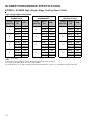
BLOWER PERFORMANCE SPECIFICATIONS
GCVM96 / ACVM96 High (Single) Stage Cooling Speed Charts
High- or Single-Stage Cooling Speeds
GCVM960604CX
ACVM960604CX
Cooling
Speed Tap
A
B
C
D
GCVM960805DX
ACVM960805DX
Adjust
Tap
CFM *
Minus(-)
594
Normal
660
Plus (+)
Cooling
Speed Tap
GCVM961005DX
High-Stage Cooling
Adjust
Tap
CFM *
Minus(-)
810
Adjust
Tap
CFM *
Minus(-)
702
Normal
900
Normal
780
726
Plus (+)
990
Plus (+)
858
Minus(-)
774
Minus(-)
990
Minus(-)
963
Normal
860
Normal
1100
Normal
1070
Plus (+)
946
Plus (+)
1210
Plus (+)
1177
Minus(-)
1035
Minus(-)
1287
Minus(-)
1242
Normal
1150
Normal
1430
Normal
1380
Plus (+)
1265
Plus (+)
1573
Plus (+)
1518
Minus(-)
1323
Minus(-)
1692
Minus(-)
1602
Normal
1470
Normal
1880
Normal
1780
Plus (+)
1617
Plus (+)
2068
Plus (+)
1958
A
B
C
D
Cooling
Speed Tap
A
B
C
D
* @ .1" - .8" w.c . ESP
Notes:
All furnaces ship as high speed for cooling. Ins taller must adjust blower speed as needed.
For most jobs, about 400 CFM per ton when c ooling is desirable.
Do not operate above .5” w.c. ESP in heating mode. Operating CFM between .5” and .8” w.c . is tabulated for cooling purposes only.
18
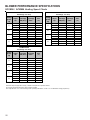
BLOWER PERFORMANCE SPECIFICATIONS
GCVM96 / ACVM96 Low Stage Cooling Speed Charts
Low-Stage Cooling Speeds
GCVM960805DX
ACVM960805DX
GCVM960604CX
ACVM960604CX
Cooling
Speed Tap
A
B
C
D
Adjust
Tap
CFM *
Minus(-)
333
Normal
370
Plus (+)
Cooling
Speed Tap
GCVM961005DX
Low-Stage Cooling
Adjust
Tap
CFM *
Minus(-)
477
Adjust
Tap
CFM *
Minus(-)
450
Normal
530
Normal
500
407
Plus (+)
583
Plus (+)
550
Minus(-)
486
Minus(-)
657
Minus(-)
666
Normal
540
Normal
730
Normal
740
Plus (+)
594
Plus (+)
803
Plus (+)
814
Minus(-)
711
Minus(-)
837
Minus(-)
828
Normal
790
Normal
930
Normal
920
Plus (+)
869
Plus (+)
1023
Plus (+)
1012
Minus(-)
882
Minus(-)
1098
Minus(-)
1044
Normal
980
Normal
1220
Normal
1160
Plus (+)
1078
Plus (+)
1342
Plus (+)
1276
A
B
C
D
Cooling
Speed Tap
A
B
C
D
* @ .1" - .8" w.c . ESP
Notes:
All furnaces ship as high speed for cooling. Ins taller must adjust blower speed as needed.
For most jobs, about 400 CFM per ton when c ooling is desirable.
Do not operate above .5” w.c. ESP in heating mode. O perating CFM between .5” and .8” w.c . is tabulated for cooling purposes only.
19
BLOWER PERFORMANCE SPECIFICATIONS
GCVM96 / ACVM96 Heating Speed Charts
GCVM960604CX / ACVM960604CX
Rise Range: 20 - 50°F)
Heating
Speed
Tap
A
B
C
D
Adjust
Tap
Minus(-)
Normal
Plus (+)
Minus(-)
Normal
Plus (+)
Minus(-)
Normal
Plus (+)
Minus(-)
Normal
Plus (+)
Low-Stage High-Stage
CFM (70%) *
CFM *
792
880
968
873
970
1,067
936
1,040
1,144
1,008
1,120
1,232
GCVM960805DX / ACVM960805DX
Rise Range: 20 - 50°F)
Rise
(°F)
1,098
1,220
1,342
1,206
1,340
1,474
1,314
1,460
1,606
1,431
1,590
1,749
48
44
40
44
40
36
40
36
33
37
33
30
Heating
Speed
Tap
A
B
C
D
Adjust
Tap
Minus(-)
Normal
Plus (+)
Minus(-)
Normal
Plus (+)
Minus(-)
Normal
Plus (+)
Minus(-)
Normal
Plus (+)
Low-Stage High-Stage
CFM (70%) *
CFM *
999
1,110
1,221
1,080
1,200
1,320
1,143
1,270
1,397
1,197
1,330
1,463
1,440
1,600
1,760
1,539
1,710
1,881
1,620
1,800
1,980
1,719
1,910
2,101
GCVM961005DX
Rise Range: 25 - 55°F)
Heating
Speed
Tap
A
B
C
D
Adjust
Tap
Low-Stage High-Stage
CFM (70%) *
CFM *
Rise
(°F)
Minus(-)
1,098
1,557
56
Normal
1,220
1,730
51
Plus (+)
1,342
1,903
46
Minus(-)
Normal
1,125
1,250
1,593
1,770
55
49
Plus (+)
1,375
1,947
45
Minus(-)
1,170
1,656
53
Normal
1,300
1,840
48
Plus (+)
1,430
2,024
43
Minus(-)
1,179
1,683
52
Normal
1,310
1,870
47
Plus (+)
1,441
2,057
43
Notes
All furnaces ship as high speed for cooling. Ins taller must adjust blower speed as needed.
For most jobs, about 400 CFM per ton when c ooling is desirable.
Do not operat e above .5” w.c. ESP in heating mode. O perating CFM between .5” and .8” w.c . is tabulated for cooling purposes only.
20
Rise
(°F)
49
44
40
46
41
38
44
39
36
41
37
34
BLOWER PERFORMANCE SPECIFICATIONS
Circulator Blower Speed Adjustment Switches
There are dual 7-segment LED's adjacent to the selection
dipswitches. The airflow rounded to the nearest 100 CFM,
is displayed on the dual 7-segment LED's. The CFM display alternates with the operating mode.
Example:
If the airlfow demand is 1230 CFM, the LED's will display
12. If the airflow demand is 1275 CFM, the LED's will display 13.
Note: Continuous fan speed is selectable on dip switches
5 & 6. Choices are 25, 50, 75, and 100 % of max CFM.
Note: The optional usage of a dehumidistat allows the
furnace’s circulator blower to operate at a slightly lower speed
(85% of desired speed) during a combined thermostat call
for cooling and dehumidistat call for dehumidification. This
can be done through an independent dehumidistat or through
a thermostat’s DEHUM terminal (if available). This lower
blower speed enhances dehumidification of the conditioned
air as it passes through the AC coil. For proper function, a
dehumidistat applied to this furnace must operate on 24
VAC and utilize a switch which opens on humidity rise.
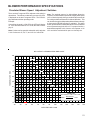
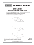
BTU OUTPUT vs TEMPERATURE RISE CHART
100
600 CFM
90
700
80
800
TEMPERATURE RISE
900
1000
70
1100
1200
60
1400
1600
50
1800
2000
2200
2400 CFM
40
30
FORMULAS
BTU OUTPUT = CFM x 1.08 x RISE
BTU OUTPUT
÷ CFM
RISE =
1.08
20
10
30
40
50
60
70
80
90
100
110
120
130
140
150
OUTPUT BTU/HR x 1000
21
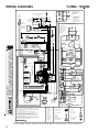
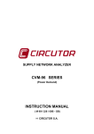
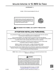
WIRING DIAGRAMS
*CVM96, *MVM96
ID BLOW ER TW O -STA GE PRES SURE
SW IT CH AS SEMBLY
HOT
SURFA CE
IGNITER
BR
L
W ARNING:DISCONNECT
POW ER BE FORE
SERVICING W IRING.
TO UNIT MUST BE
PROPE RLY POLA RIZED
AND GRO UNDED.
BK
HIGH FIRE
PRESSURE
S W IT CH
OR
LOW FIRE
P RE SSURE
C
C
NO
SW IT CH
N
WH
DISCONNECT
NO
YL
2 CIRCUIT
CONNE CT OR
BR
2 1
TO
115 VAC/1 Ø /60 HZ
POW ER S UPP LY W ITH
OVE RCURRENT
PROTECTION
DE VICE
GND
JUNCTION BO X
24V
HUM.
TO 115VA C/1
Ø /60 HZ POW ER SUPPLY W ITH
O VERCURRENT PROTECT IO N DEVICE
RD
OR
GND
L
MODULATING
WH
2
C
GAS VALVE
FLAME
( HO NEY W ELL)
C
GY
1
PM
N
W ARNING:
BR
SENSOR
GY
NO
DIS CONNE CT POW ER
BEFORE SERVICING
W IRING TO UNIT
MUST BE PROP ERLY
POLARIZE D A ND
GRO UNDE D.
FRONT COVE R
PRESSURE S W IT CH
D IS CON NECT
MANUAL RESE T ROLLOUT LIM IT CONTROLS
(SING LE CONT ROL ON 45 kBTU)
PU
PK
DOOR
SW ITCH
JUNCTION B OX
INDUC TOR COIL
70 kBTU,9 0kB TU,
11 5kB TU MODEL S
ONL Y
OR
PU
3
2
RD
1
BK
BL W R
GND
LINE
BK
RD
YL
NEUTRA L
GND
EA C
NE UTRA L
ELECTRONIC
AIR CLEANE R
OR
PU
RD
NE UTRAL
ID BL OWE R
CONNECTOR
INTEGRATED CONTROL MODULE
PU
AUT O RESET
AUXILIARY
LIMIT CO NTROL
INTEGRATED CONTROL MODULE
OR
WH
BLOW E R COMPA RTMENT
INDOO R
A IR
CIRCUL ATOR
GR
INDUCED
DRAFT
BLOW ER
WH
BURNER COMPARTMENT
HIGH VOLTAGE!
DISCONNECT ALL POWER BEFORE SERVICING OR INSTALLING THIS
UNIT. MULTIPLE POWER SOURCES MAY BE PRESENT. FAILURE TO
DO SO MAY CAUSE PROPERTY DAMAGE, PERSONAL INJURY OR DEATH.
CHASSIS
G ROUND
BL
OR
AUT O RESET PRIMARY
LIMIT CONTROL
OPTIONAL
3
2
3 Ø ID
BLWR
1
HUM
NE UTRAL
HUMIDIFIE R
O PTIONAL
IG N
NE UTRAL
HOT SURFAC E
IGNITER
FS
1
2
3
BL
FLA ME
SE NSOR
BK
LINE
11 5
VA C
LINE
40 VA
TRANS FO RM ER
HUM
FAN TAPS
BR
BK
HE AT TA PS
CO OL TA PS
HSI
E AC
FUSE 3A
3
4
2
1
BR
OR
GY
7
10
4
1
GY
8
11
5
2
YL
9
12
6
3
OR
P ULL DOWN
24 VAC
AUTO RESET AUXIL IARY LIMIT
CO NTROLS
Y1
(6)
L OW FIRE P RESS.
S WITCH
W1
C
(12)
NO
W2
NO
(2)
TO
MICR O
C
HIGH FIRE
MA NUAL RESET RO LL OU T
LIMIT CONT ROLS
P RESS. SW ITCH
BL
RD
O
Y1
Y2
W2
W1
C
R
G
2
1
DE H UM
G
WH
AU TO RESET PRIMARY
LIMIT CO NTROL
( 3)
Y2
OR
DE HUM
PULL UP
BIAS
COOL S ETUP
HEAT S ETU P
DIP SW ITC HES
ADJUST
HE AT OFF
DELAY
RA MPING
115
VAC
TR (5)
TO +VDC
24
V AC
NEUTRA L
40 VA
TR ANSFORM ER
R
24V THERMOS TAT CONNECTIONS
MODULATING INTERGRATED
FURNACE CONTROL MODULE
FLAME
S ENSOR
DIAGNOS TIC
LED'S
(11)
O
F USE
2 4 V TH ERMOSTA T CO NNECTIO NS
BK
24 V 3A
AUX
D EHUM
24 V HUM .
GY
C
E CM MTR
FR ONT COVE R
P RE SS . SW ITCH
C
C
(10)
BL
RD G Y
GA S
VA LV E
GND (4)
WH
TO
R
3
2
1
WH
5
4
3
2
1
TR (9 )
BK
BK
WH
BK
WH
GR
G ND
GND (4 )
+ VDC (1 )
PK
BLOW E R
NOTES:
1. SET HEAT A NT ICIPAT OR ON ROOM THERMOSTA T A T 0.7 A MPS .
2. M ANUFACTURER'S SPE CIFIED REPLACEME NT P ARTS MUST B E
USED W HE N SERVICING.
3. IF ANY OF THE ORIGINAL W IRE A S SUPPLIED W ITH THE
FURNACE MUST B E REPLA CE D, IT MUST BE REPLACED W ITH
W IRING MA TERIAL HAVING A T EMPE RA TURE RATING OF AT
LEAST 105°C. US E CO PPER CONDUCTO RS ONLY.
4. UNIT MUST B E P ERMANENTLY GROUNDED AND CONFORM TO
N.E.C. AND LOCAL CO DES.
5. TO RE CALL THE LAST 10 FAULTS, MO ST RECENT TO LEAST
RECENT, DE PRE SS SW ITCH FOR MORE T HAN 2 SECONDS W HILE
IN STANDBY (NO THERMOS TAT INPUTS )
INDO OR
AIR
C IRCUL ATOR
B LW R
R X ( 2)
GND
WH
WH
CIRCULATOR
PM
( 7)
BK
4
HARNE SS
NO
( 8)
INDUCTOR COIL
70kBTU,90kBTU,
115k BTU MODELS
ONLY
COLOR CODES:
BLOW E R
COMPART MENT
DOOR SW ITCH
(OPE N W HEN
DOOR OPEN)
TO
MICRO
T X (3)
INTEG RATE D CONTR OL
MODULE
HUMIDIFIER
O PTIONAL
LOW VOLTAGE F IELD
E QUIP MENT GND
PK P INK
BR BROW N
LOW V OLTAGE (24V)
F IE LD GND
FIELD SP LICE
W H W HITE
B L BLUE
HI VO LTAGE (115V)
GY GRAY
HI VO LTA GE FIELD
RD RE D
YL YELLOW
OR O RA NGE
JUNCTION
PU PURP LE
SW ITCH (TEM P)
IGNIT ER
TE RMINAL
GR G REEN
INT ERNAL T O
INTEGRATE D CONTROL
BK BLACK
PLUG CONNE CT ION
SW ITCH P RE SSURE
OVERCURRENT
PROT. DEVICE
0140F00863-B
Wiring is subject to change, always refer to the wiring diagram on the unit for the most up-to-date wiring.
22