1
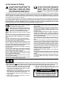
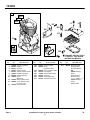
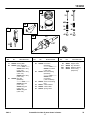
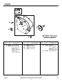
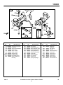
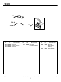
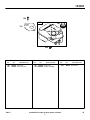
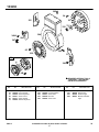
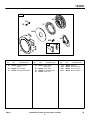
FORM MS–1992–7/98
REPLACES FORM MS–1992–4/98
FILE IN SECT. 2 OF SERVICE MANUAL
RAPTOR II RACING ENGINES
$1.50
Illustrated Parts List
Motorsports
Model Series
133230
TYPE NUMBER
8014.
WARNING:
MODEL 133230–8014–01 IS A RACING ENGINE
SPECIAL SKILLS AND KNOWLEDGE ARE REQUIRED TO PREPARE THE
ENGINES FOR COMPETITIVE USE. IF YOU ARE NOT FAMILIAR WITH THE
PROPER TECHNIQUES AND PROCEDURES, HAVE QUALIFIED
INDIVIDUALS DO THE WORK FOR YOU
THE ENGINES DO NOT HAVE GOVERNORS. ANY THROTTLE MECHANISM
MUST HAVE A RETURN–TO–IDLE SPRING SO THE ENGINE WILL RETURN
TO IDLE SPEED WHEN THE THROTTLE PEDAL IS RELEASED
FAILURE TO FOLLOW THESE WARNINGS COULD
RESULT IN SERIOUS PERSONAL INJURY OR DEATH
TO FIND
THE CORRECT NUMBER OF THE PART YOU NEED:
FOLLOW THE INSTRUCTIONS ON THE REVERSE SIDE
A.
B.
C.
D.
E.
F.
Refer to Engine Model, Type and Code Number that is stamped on the blower housing of engine.
Engine type numbers such as 0123 01 are listed only as 0123 in most instances. The two digits (01
or 02, etc.) to the right of the space may be required for more accurate parts identification in some
instances. Select the Illustrated Parts List covering the correct Model Series and Type Number.
Refer to the Illustrations and compare the original part with Illustration. The number next to the
illustration is the Reference Number. Assemblies include all parts shown in frames. All parts shown
in assembly frames having individual reference numbers can be purchased separately.
After the Reference Number has been identified, refer to the Numerical text, where Reference and
Primary Part Number are listed. THE PRIMARY PART IS USED ON ALL TYPE NUMBERS
EXCEPT THOSE TYPE NUMBERS UNDER “NOTE.”
If a “Note” appears below the Primary Part Number, it means that this part differs from the Primary
Part for certain types. If your Type number is listed under “Note,” order the part referred to at the
“Note.”
If your Engine Type Number does not appear after any part number listed under “Note,” use the
Primary Part Number.
For Engine Type Numbers not covered by this book, check other Parts Lists having the same
engine model or contact your source of supply.
PRINTED IN U.S.A.
COPYRIGHT by BRIGGS & STRATTON CORPORATION
All rights reserved. No part of this material may be reproduced or transmitted,
in any form or by any means, electronic or mechanical, including photocopying,
recording or by any information storage and retrieval system, without permission
in writing from Briggs & Stratton Corporation.
In the Interest of Safety
This safety alert symbol indicates that this
message involves personal safety. The
words “danger”, “warning” and “caution”
indicate degree of hazard. Death, personal
injury and/or property damage may occur
unless instructions are followed carefully.
You are not ready to operate this engine if
you have not read and understood the
following safety items. Read the entire
owner’s manual and the operating
instructions of the equipment this engine
powers.
The Briggs & Stratton engine is made of the finest material in a state-of-the-art manufacturing facility. Please understand that Briggs
& Stratton sells engines to original equipment manufacturers. It also sells to others in the distribution chain who may sell to the
ultimate consumer, an equipment manufacturer, another distributor or a dealer. As a result, Briggs & Stratton does not necessarily
know the application on which the engine will be placed. For that reason, carefully read and understand the operating instructions of
the equipment before you repair or operate it.
You should also understand that there are equipment applications for which Briggs & Stratton does not approve the use of its engines. Briggs & Stratton engines are not to be used on vehicles with less than 4 wheels. They include motor bikes, aircraft products
and All Terrain Vehicles. Moreover, Briggs & Stratton does not approve of its engines being used in competitive events. FOR THAT
REASON, BRIGGS & STRATTON ENGINES ARE NOT AUTHORIZED FOR ANY OF THESE APPLICATIONS. Failure to follow
this warning could result in death, serious injury (including paralysis) or property damage.
DO NOT run engine in an enclosed area.
(Exhaust gases contain carbon monoxide,
an odorless and deadly poison.)
DO NOT remove fuel tank cap nor fill fuel tank
while engine is hot or running. DO NOT refuel
indoors or in an unventilated area. (Allow engine to cool 2 minutes before refueling.)
DO NOT place hands or feet near moving or rotating
parts.
DO NOT store, spill, or use gasoline near an open
flame, nor near an appliance like a stove, furnace, or
water heater that uses a pilot light or can create a
spark.
DO NOT refuel indoors or in an unventilated area.
DO NOT operate or tip engine/equipment at such a severe angle that causes gasoline spillage.
DO NOT operate engine if gasoline is spilled or when
smell of gasoline is present or other explosive conditions exist. (Move equipment away from spill and avoid
any ignition until gasoline has evaporated.)
DO NOT transport engine with fuel in tank or fuel shutoff valve open.
DO NOT choke carburetor to stop engine, especially in
an enclosed vehicle. (Whenever possible, gradually
reduce engine speed before stopping.)
DO NOT tamper with governor springs, links or other
parts to increase engine speed. (Run engine at speed
set for equipment manufacturer.)
DO NOT check for spark with spark plug removed.
(Use an approved tester.)
DO NOT run engine without blower housing or other
safety shields removed when doing repairs.
DO NOT crank engine with spark plug removed. (If engine is flooded, place throttle in FAST and crank until
engine starts.)
DO NOT strike flywheel with a hammer or hard object as
this may cause flywheel to shatter in operation. (To remove flywheel, use Briggs & Stratton approved tools and
procedures only.)
DO NOT operate engine without a muffler. (Inspect periodically and replace if worn or leaking. If engine is
equipped with muffler deflector, inspect periodically and
replace if necessary. Replacement parts must be same
as on original equipment.)
DO NOT operate engine with an accumulation of
grass, leaves or other combustible material in muffler
area.
DO NOT use this engine on any forest covered, brush
covered, or grass covered unimproved land unless a
spark arrester is installed on muffler. The spark arrester must be maintained in working order by the owner
and/or operator. In the State of California the above is
required by law (Section 4442 of the California Public
Resources Code). Other states may have similar laws.
Federal laws apply on federal lands.
DO NOT touch hot muffler, cylinder, or fins which can
cause burns.
DO NOT start engine with air cleaner or air cleaner cover
removed (or cover over carburetor air intake, if Sno/Gard
engine).
DO NOT attempt to start engine with cutting blade loose
or removed. (Blade must be tight, otherwise a kickback
may occur.)
✔Prior to work, read and understand the section(s) of this manual that pertain to the job. Follow all safety warnings.
✔PULL starter cord slowly until resistance is felt. Then pull cord rapidly to avoid kickback and prevent hand or arm injury.
✔WEAR suitable eye protection (safety glasses, goggles or face shield when performing repair procedures.
✔ PREVENT ACCIDENTAL STARTING by removing spark
plug wire from spark plug when servicing engine or equipment. Disconnect negative wire from battery terminal if
equipped with electric starting system.
✔ REMOVE blower housing periodically and clean engine.
Keep cylinder fins and governor parts free of dirt, grass
and other debris which can affect engine speed.
✔ USE fresh gasoline. Stale fuel can gum carburetor and
cause leakage.
✔ CHECK fuel lines and fittings frequently for cracks or
leaks. Replace if necessary.
✔ USE ONLY Genuine Briggs & Stratton Parts or their
equivalent. The use of replacement parts which are not of
equivalent quality may damage the engine.
WARNING:
The engine exhaust from this product
contains chemicals known to the State
of California to cause cancer, birth
defects, or other reproductive harm.
133230
1
870
871
869
13
307
14
383
306
308
337
15
5
2
8
7
3
529
9
REQUIRES SPECIAL TOOLS
TO INSTALL. SEE REPAIR
INSTRUCTION MANUAL.
10
REF.
NO.
PART
NO.
1
2
3
5
7
8
9
10
555206
555140
555071
555257
555187
555073
555036
555043
13
14
15
REF.
NO.
DESCRIPTION
Cylinder Assembly
Bushing
Seal–Oil
Head–Cylinder
Gasket–Cylinder Head
Breather Assembly
Gasket–Breather
Screw
(Breather)
555082 Stud–Cylinder Head
555045 Screw Cylinder Head
(2 15/32” Long)
555079 Plug–Oil Drain
Included in Gasket Set–Part No. 555210.
1992–2
306
307
308
337
383
529
869
870
PART
NO.
REF.
NO.
DESCRIPTION
555057 Shield–Cylinder
555046 Screw
(Cylinder Shield)
555056 Cover–Cylinder Head
555132 Plug–Spark
89838 Wrench–Spark Plug
555074 Grommet
555136 Seat–Intake Valve
555137 Seat–Exhaust Valve
871
PART
NO.
DESCRIPTION
555214 Bushing–Guide
Exhaust Valve)
(Sintered Bronze)
OR
555158 Bushing–
Guide
Exhaust Valve)
(Sintered Iron)
––––––– Note –––––
555139 Bushing–
Guide
(Intake Valve)
Included in Carburetor Kit–Part No. 555130.
Assemblies include all parts shown in frames.
2
78
133230
25
26
33
34
456
28
36
36
27
29
40
40
45
45
27
16
741
377
32
17
REF.
NO.
16
17
25
26
PART
NO.
REF.
NO.
DESCRIPTION
555204 Crankshaft
555050 Bearing–Ball
555092 Piston Assembly
––––––– Note –––––
555093 Piston Assy.
(.010” O.S.)
555094 Piston Assy.
(.020” O.S.)
555095 Piston Assy.
(.030” O.S.)
555088 Ring Set
(Standard)
––––––– Note –––––
555089 Ring Set
(.010” O.S.)
555090 Ring Set
(.020” O.S.)
555091 Ring Set
(.030” O.S.)
Included in Gasket Set–Part No. 555210.
1992–3
27
28
29
32
33
34
36
PART
NO.
DESCRIPTION
555035 Lock–Piston Pin
555058 Pin–Piston
(Standard)
––––––– Note –––––
555059 Pin–Piston
(.005” O.S.)
555207 Rod–Connecting
(Standard)
––––––– Note –––––
555208 Rod–
Connecting
(.020” Undersize)
555070 Screw–Connecting
Rod
555077 Valve–Exhaust
555062 Valve–Intake
555076 Spring–Valve
REF.
NO.
40
45
377
456
741
PART
NO.
555039
555061
555049
555147
555235
DESCRIPTION
Retainer–Spring
Tappet–Valve
Key–Woodruff
Retainer–Spring
Gear–Timing
(Tempered)
Included in Carburetor Kit–Part No. 555130.
Assemblies include all parts shown in frames.
3
78
133230
21A
116
12
4
22
46
20
REQUIRES SPECIAL TOOLS
TO INSTALL. SEE REPAIR
INSTRUCTION MANUAL.
21
REF.
NO.
4
12
PART
NO.
REF.
NO.
DESCRIPTION
555209 Cover–Crankcase
555191 Gasket–Crankcase
(.015” Thick, Std.)
555064 Gasket–
Crkcse. (.005” Thick)
555065 Gasket–
Crkcse. (.009” Thick)
20
21
21A
22
555087
555037
555138
555047
DESCRIPTION
REF.
NO.
46
Seal–Oil
Plug–Oil Fill
Plug–Oil Fill
Screw–Hex.
116
Included in Gasket Set–Part No. 555210.
1992–4
PART
NO.
PART
NO.
DESCRIPTION
555052 Gear–Cam
(Machined Lobes)
––––––– Note –––––
555000 Gear–Cam
(Unmachined Lobes)
555135 Ring–Oil Retainer
Included in Carburetor Kit–Part No. 555130.
Assemblies include all parts shown in frames.
4
78
133230
90
232
97
95
152
154
634
212
96
51
203
392
611
681
127
147
116A
114
117
148
149
94
612A
124
REF.
NO.
PART
NO.
REF.
NO.
DESCRIPTION
51 555078 Gasket–Intake Elbow
90
555129 Carburetor
94 555124 Valve–Idle Adjustment
95
555232 Screw–Hex.
96
555109 Valve–Throttle
97
555100 Shaft–Throttle
114 555106 Gasket–Valve
116A 555122 Packing–Valve
117 555126 Nut–Needle Valve
124
555238 Screw–Carburetor
Mounting
Included in Gasket Set–Part No. 555210.
1992–5
127
147
148
149
152
154
203
205
212
232
392
PART
NO.
205
432
612
394
434
433
REF.
NO.
DESCRIPTION
555105 Plug–Welch
394
555114 Seat–Needle Valve
555125 Washer–Needle Valve
555123 Spring–Needle Valve
555101
555102
555104
555110
555116
555117
555115
435
Spring–Adjustment
Screw–Round Head
Crank–Bell
Screw–Shoulder
Link–Throttle
Spring–Link
Spring–Diaphragm
432
433
434
435
611
612
612A
634
681
PART
NO.
DESCRIPTION
555119 Diaphragm–
555113
555108
555112
555107
555103
555128
555120
555118
555127
Carburetor
Cap–Spring
Pin–Roll
Cover–Diaphragm
Screw–Hex.
Tube–Pick–up
Tube–Pick-up
Tube–Pick-up
Washer–Shaft
Valve–Needle Kit
Included in Carburetor Kit–Part No. 555130.
Assemblies include all parts shown in frames.
5
78
133230
356
333
284
REF.
NO.
284
333
335
PART
NO.
851
335
356A
REF.
NO.
DESCRIPTION
555080 Screw–Hex.
555075 Armature–Magneto
555040 Screw–Hex.
356
PART
NO.
DESCRIPTION
555086 Wire–Stop
(Armature to Switch)
REF.
NO.
356A
851
Included in Gasket Set–Part No. 555210.
1992–6
PART
NO.
DESCRIPTION
555099 Wire–Stop
(Stop Switch to
Ground)
555072 Terminal–Cable
Included in Carburetor Kit–Part No. 555130.
Assemblies include all parts shown in frames.
6
78
133230
190
180
181
191
526
REF.
NO.
180
181
PART
NO.
REF.
NO.
DESCRIPTION
555192 Tank–Fuel
555085 Cap–Fuel Tank
DESCRIPTION
190
555048 Screw–Hex.
191 555084 Gasket–Tank Mtg.
Included in Gasket Set–Part No. 555210.
1992–7
PART
NO.
REF.
NO.
526
PART
NO.
DESCRIPTION
555044 Screw–Hex.
Included in Carburetor Kit–Part No. 555130.
Assemblies include all parts shown in frames.
7
78
133230
305
24
23
215
75
332
304
346A
984
347
65
305
930
37
66
346
346
REQUIRES SPECIAL TOOLS
TO INSTALL. SEE REPAIR
INSTRUCTION MANUAL.
REF.
NO.
PART
NO.
23
24
37
65
66
75
555067
555054
555053
555211
555171
555083
REF.
NO.
DESCRIPTION
Flywheel
Key–Flywheel
Guard–Flywheel
Screw–Torx
Clutch–Starter
Washer–Flywheel
215
304
305
332
346
Included in Gasket Set–Part No. 555210.
1992–8
PART
NO.
555055
555256
555051
555038
555046
DESCRIPTION
Guide–Air
Housing–Blower
Screw–Hex.
Nut–Hex.
Screw–Hex.
REF.
NO.
346A
347
930
984
PART
NO.
555081
555098
555255
555097
DESCRIPTION
Screw–Hex.
Switch–Stop
Guard–Finger
Bracket–Indicator
Light
Included in Carburetor Kit–Part No. 555130.
Assemblies include all parts shown in frames.
8
78
133230
608
56
373
57
65
1016
58
655
60
59
55
REF.
NO.
55
56
57
PART
NO.
REF.
NO.
DESCRIPTION
555222 Housing–Rewind
Starter
555224 Pulley–Starter
555226 Spring–Rewind Starter
Included in Gasket Set–Part No. 555210.
1992–9
58
59
60
65
PART
NO.
DESCRIPTION
555221 Rope–Starter
(63” Long)
555227 Insert–Grip
555228 Grip–Starter Rope
555229 Screw–Hex.
REF.
NO.
373
608
655
1016
PART
NO.
555230
555165
555223
555225
DESCRIPTION
Nut–Hex.
Starter–Rewind
Anchor–Spring
Spacer–Rewind
Included in Carburetor Kit–Part No. 555130.
Assemblies include all parts shown in frames.
9
78
133230
358 GASKET SET
121 CARBURETOR KIT
681
3
20
51
147
114
9
394
117
116A
148
7
149
94
116
51
12
191
191
REF.
NO.
PART
NO.
3
7
9
12
555071
555187
555036
555191
REF.
NO.
DESCRIPTION
Seal–Oil
Gasket–Cylinder Head
Gasket–Breather
Gasket–Crankcase
(.015” Thick, Std.)
555064 Gasket–
Crankcase
(.005” Thick)
555065 Gasket–
Crankcase
(.009” Thick)
Included in Gasket Set–Part No. 555210.
1992–10
PART
NO.
REF.
NO.
DESCRIPTION
20 555087 Seal–Oil
51 555078 Gasket–Intake Elbow
94 555124 Valve–Idle Adjustment
114 555106 Gasket–Valve
116 555135 Ring–Oil Retainer
116A 555122 Packing Valve
117 555126 Nut–Needle Valve
121
555130 Carburetor Kit
147 555114 Seat–Needle Valve
148 555125 Washer–Needle Valve
PART
NO.
DESCRIPTION
149 555123 Spring–Needle Valve
191 555084 Gasket–Tank Mtg.
358
555210 Gasket Set
394 555119 Diaphragm–
Carburetor
681 555127 Valve–Needle Kit
Included in Carburetor Kit–Part No. 555130.
Assemblies include all parts shown in frames.
10
78