1
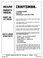
OWNER'S
MANUAl.
MODELNO.
247.346250
CRRFTSMRN
Caution:
ReadandFollow
All SafetyRules
andInstructions
BeforeOperating
ThisEquipment
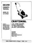
5.0 HORSEPOWER
25.5 TON
HYDRAULIC LOG SPLITTER
Assembly
Operation
Customer Responsibilities
Service and Adjustment
RepairParts
" SEARS ROEBUCKANDCO Chicago IL 60684 U S A ........
Ill
IIIII
I;_
_
iiiiiiiiiiiiiiiiiiII
IIII
g
_
i
IJ_
i
•
•
•
iii
IIIIIIIIH
IMPORTAN[
=ill|
i
i
ii
i
SAFETYRULES
I
•
II
I
IIIIIII IIIIIIIIIIIIIIIIIIIIIII
l Ill
I
Rill
IIIIIIIII
ALSAFETY
AND/ORPROPERTY
OFYOURSELF
ANDOTHERS.READANDFOLLOW
ALL INSTRUCTIONS
IN THISMANUALBEFORE
ATTEMPTING
TPOINTS
OOPERATE
YOURLOGSPLITTER.
FAILURE
TOCOMPLY
WITHTHESE
INSTRUCTIONS
IN PERSONTHISSYMBOL
OUTIMPORTANT
SAFETYINSTRUCTIONS
WHICH,
IF NOTFOLLOWED,
COULDMAYRESULT
ENDANGER
THEPERSON-A
ALINJURY.WHENYOUSEETHISSYMBOL-- ,_ HEEDiTSWARNING.
,_
&
DANGER
Your log splitter was built to be operated accordingto the rules for safe operation in this manual. As with
any b/pe of power equipment, carelessness or error on the part of the operator can result in serious
injury. If youviolate any of these rules, youmay cause seriousinjury to yourself or others.
TRAINING
1. Beforeoperatingthissplitter,readandunderstand
thismanual
completely.
Becomefamiliarwithit for yourownsafety.To tail
to do so may cause seriousinjury.Do not allow anyoneto
operateyoursplitterwho hasnot readthismanual Keepthis
manualin a safeplacefor futureandregularreference
andfor
ordering
replacement
parts.
2. Never useyour splitterfor anyotherpurposethansplitting
wood.tt isdesigned
for thisuseandany otherusemaycause
an injury.Yourlogsplitteris a precision
pieceof powerequipment, not a toy. Therefore,exerciseextremecautionat all
times,
3. Neverallowchildrento operateyourlogsplitter. Do notallow
adults to operateit withoutproperinstruction.
Onlypersons
wellacquainted
withtheserulesof safeoperationshouldbe
allowedto useyourlogsplitter.
4. Onlytheoperatoris to be nearyourtog splitterduringuse,
Keepall others,includingpets and children,
a minimumof 20
feet away from yourwork zone. Flyingwoodcan be hazardous.If a helperisassistingin loadinglogs,neveractivate
thecontroluntilthehelperisclearofthearea.Moreaccidents
occurwhen more thanone personoperatesthe log splitter
thanat anyothertime.
5. Nooneshouldoperatethisunitwhileintoxicated
or whiletakingmedicationthat impairsthe sensesor reactions.A clear
mindis essential
for safety.Neverallowa personwho istired
or otherwisenot alertto useyoursplitter.
8. Only operateyour splitter on level ground and not on the side
of a hill. it couldtip, or roiling logs or poorfooting couldcause
an accident. Operating the splitter on level ground also prevents the spillage of gasoline from the fuel tank.
9. Never attemptto move the log splitter over hilly or uneventerrain without a tow vehicle or adequate help.
10. Always block the wheels to prevent movement of log splitter
while in operation.
11. Check the fuel before starting the engine. Gasoline is an
extremely flammable fuel. Do not fill the gasoline tank indoors,
when the engine is running, or while the engine is still hot.
Replacegasolinecap securely and wipe off any spilled gasoline
before starting the engineas it may causea tire or explosion.
12. Both ends of each log must be cut as square as possibleto
help preventthe log from riding out of the splitter during operation.
&
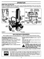
OPERATION
1. Standbehindthereservoir
tankwhenoperating.
Seeillustrations.
PREPARATION
1. Neverwear loose clothing or jewelrythat canbecaughtby
moving partsof your log splitterand pull you into it. Keep
clothingawayfromallmovingpartsofyourlogsplitter.
2. Wearproperheadgearto keephair awayfrom movingparts.
Alwayswearprotectivehearingdevices
as needed.
3. Alwayswearsafetyshoes.A droppedlog canseriously
injure
yourfoot.
4. Alwayswearsafetyglassesor goggles whileoperatingyour
splitter.Apieceof splitting
logcouldflyoff andhityoureyes.
5. Ifyou weargloves,besuretheyaretightfitting withoutloose
cuffsor drawstrings.
6. Useyourlogsplitterindaylight,or undergoodartificial
light.
7. Neveroperateyoursplitteron slippery,wet,muddyor icysurfaces.Safefootingisessentia!in preventing
accidents.Never
operateyoursplitterwhileattachedtoa towingvehicle.
/
3, Replace all damaged or worn parts such as hydraulic hoses
and fittings immediately with manufacturer approvedreplacement parts.
4. Do not change the engine governor settingsor overspeed the
engine. This increases the hazardof personal injury.The maximum engine speed is preset by the manufacturer andis within
safety limits.
5. Do not alter your splitter in any manner such as attaching a
rope or extensionto the control lever or adding to the width or
height of the wedge. Such alterations may causeyour splitter
to be unsafe.
2. Know how to stop the unitand disengage the controls.
3. Never placehands or feet between log and splitting wedge or
between log and end plateduring forward or reverse stroke. To
do so may result in crushed or amputated fingers or toes, or
worse, you may lose an arm or foot.
4. Do not straddle the splitter when using it. A slip in any position
could result in a serious injur),.
5. Do not step over your log splitter when the engineis running.
You may trip or accidentallyactivate the splitting wedge if you
step over. If you need to get to the other side, walkaround.
6. Never try to split two logs on top of each other. One may fly
out and injure you.
7. When loading the log splitter, place your hands on the side of
the log, not at the ends. Never attempt to load your splitter
while the splitting wedge is in motion. You may get caught by
the wedge and injured.
8. Only use your hand to operate the splitting wedge or control
lever. Never use your foot or a rope or any other extension
device, This could result in your inabilityto stop your splitter
quickly enoughto avoid injury,
9. Always keepfingers awayfrom any cracksthat open in the log
during splitting operation.They can quickly closeand pinchor
amputate your fingers,
10, Never attempt to split woods acrossthe grain. Some types of
wood may burst or fly out of your splitterand resultin injuryto
you or a bystander,
11. For logsthat are not cut square,the longest portionof the tog
should be rotated down and the most square end placed
againstthe splittingwedge,
12, Keep your work area clean. Immediately remove split wood
around your splitterso that you do not stumble over it, Clean
chips and dirt off end plate (wood platform) after each tog is
split, or whenever necessary to maintain flat contact between
wood and endplate (platform).
13. Never move the log splitter whilethe engine is running.
14. Never leave your Iog splitter unattendedwith the enginerunning. Shut off the engineif you are leaving your splitter, even
for a short period of time. Someone couldaccidentally activate
the splitting wedge and beinjured.
6. Perform all recommended maintenance procedures before you
use your splitter.
7. Do not serviceor repair your togsplitter without disconnecting
the spark plug wire and moving it away from the spark plug.
8. Neverstore the equipment with gasoline in the tank insideof a
building where ignition sources are present, such as hot water
and space heaters, clothes dryers and the like. Allow the
engineto cool before storing in any enclosure.
9. Alwaysstore gasoline in an approved, tightly sealed container.
Store the containerin a cool, dry place. Do not store in a building where ignition sources are present.
10. To reducefire hazard, keep engine free of grass, teaves,wood
chips,and excessive grease and oil.
11. The hydraulic system of your log splitter requires careful
inspection, along with the mechanical parts.Be sure to replace
frayed, kinked, or otherwise damagedhydraulic components.
12. Fluid escaping from a very small hole can be almost invisible.
Do not check for leaks with your hand. Escaping fluid under
pressure can have sufficient force to penetrate skin, causing
serious personal injury. Leaks can be located by passing a
pieceof cardboardor wood over the suspected leak and looking for discoloration.
13. Should it become necessaryto loosenor remove any hydraulic
fitting or line, be sure to relieveall pressure by shutting of/the
engine and moving the control handle back and forth several
times.
14. Do not remove the cap from the hydraulictank or reservoir
while your log splitter is running. Hot oil under pressure could
cause injury.
15. The pressurerelief valve on your splitter is preset at the factory. Do not adjustthe valve, Only a qualified service technician
should perform this adjustment.
16. Completelydrainfuel tank prior to storage, Thisguardsagainst
accumulationof fuel fumes which couldresultin a fire hazard.
15. Do not run engine in an enclosed area. Exhaust gases contain
carbon monoxide. This odorless gas can be deadly when
inhaled.
16. Be carefulnot to touch the muffler after the engine has been
running. It will be HOT!
17. If the equipment should start to vibrate abnormally, stop the
engine and check immediately for the cause, Vibration is generally a warning of trouble.
18. When cleaning, repairing or inspecting,make certainall moving parts have stopped. Disconnect the spark plug wire and
keep the wire away from the plug to prevent accidental starting.
.
17. Never store log splitter outside without a waterproof cover.
Rainwiltcause rust on the inside of the cylinder.
TOWING
1. This unitshouldnot be towed on any street, highwayor public
road without checking the existingfederal, focal or state vehicle requirements. Any licensing or modifications such as taillights, etc., neededto comply with the existingfederal, local or
state vehiclerequirementsis the sole responsibility of the purchaser.
2. Before towing, be certain the log splitter is correctly and
securelyattachedto the towing vehicle, and the safety chains
are in place.Leave slackin chainsfor turning allowance.
3. Do not allow anyone to sit or ride on your splitter. They can
easilyfall off and be seriously injured.
CUSTOMER RESPONSIBILITIES
Do not operateyour splitterin poormechanicalconditionor
whenin needofrepair.
Periodicallycheckthatall nuts, bolts,screws,hoseclampsand
hydraulicfittings are tight to be sureequipmentis in safe
workingcondition.
Whereappropriate,
checkall saletyguards
and shieldsto be suretheyare in the properposition.Never
operateyoursplitterwithsafety guards,shieldsor otherprotectivefeaturesremoved.Thesesafetydevicesare for your
protection.
3
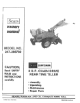
CONGRATULATIONS
on your purchase of a Sears
Craftsman tog splitter, it has been designed, engineered
and manufactured to give you the best possible dependability and performance.
Should you experience any problem you cannot easily rem*
edy, please return the lawn mower to the nearest Sears
Service Center/Department in the United States. We have
competent, well-trained technicians and the proper tools to
service or repair this unit.
Please read and retain this manual. The instructions will
enable you to assemble and maintain your log splitter properly. Always observe the "SAFETY RULES,"
MODEL
NUMBER
PRODUCT
SPECIFICATIONS
Horsepower:
5.0
Displacement:
12.57 cu. in.
Fuel Capacity:
1 Gallon
(Unleaded)
Spark Plug (Gap .030 in.):
Champion
J 19LM (or
Equivalent)
Magnetron® Ignition Air Gap:
.0125 in.
247.346250
Tire Pressure
SERIAL
NUMBER
DATE OF
PURCHASE
MAINTENANCE
THE MODEL AND SERIAL NUMBERS WILL BE FOUND
ON A LABEL ATTACHED TO THE FRAME.
YOU SHOULD RECORD BOTH SERIAL NUMBER AND
DATE OF PURCHASE AND KEEP IN A SAFE PLACE
FOR FUTURE REFERENCE.
CUSTOMER
RESPONSIBILITIES
•
•
Read and observe the safety rules.
Follow a regular schedule in maintaining, caring for
and using your log splitter.
• Follow the instructions under =Customer
Responsibilities" and "Storage" sections of this
Owner's Manual.
12-15 p.s.i.
AGREEMENT
A Sears Maintenance Agreement is available on this
product.Contactyour nearest Searsstore for details.
WARNING: This unit is equipped with an internal combustion engine and should not be used on or near any
unimproved forest-covered, brush-covered or grass-covered
land unless the engine's exhaust system is equipped with a
spark arrester meeting applicable local or state laws (if any).
If a spark arrester is used, it should be maintained in
effective working order by the operator.
In the State of California
the above is required by law
(Section 4442 of the California Public Resources Code).
Other states may have similar laws. Federal laws apply on
federal lands. A spark arrester for the muffler is available
through your nearest Sears Authorized Service Center.
(See the REPAIR PARTS section of this manual.)
ONEYEARLIMITEDWARRANTYON CRAFTSMANLOGSPLITTER
For one year from the date of purchase, when this Craftsman Log Splitter is maintained and lubricated according to the instructions in the owner's manual, Sears will repair, free of charge, any defect in material and workmanship.
If this Craftsman log splitter is used for commercial
date of purchase.
purposes, this warranty applies for only 30 days from the
This warranty does not cover:
• Expendable items which become worn during normal use, such as air cleaners and spark plugs.
• Repairs necessary because of operator abuse or negligence, including the failure to maintain the equipment
according to the instructions contained in the owner's manual.
WARRANTY SERVICE IS AVAILABLE BY RETURNING THE CRAFTSMAN LOG SPLITTER TO THE NEAREST SEARS SERVICE CENTER!DEPARTMENT
IN THE UNITED STATES. THIS WARRANTY APPLIES
ONLY WHILE THIS PRODUCT IS IN USE IN THE UNITED STATES.
This warranty gives you specific legal rights, and you may also have other rights which may vary from state to
state.
SEARS, ROEBUCK AND CO., D/817WA, Hoffman Estates, tL 60179
i
SAFET
_(
i
RULES
iiiiiiiii
iiiii
iL
i
II
.....................................................
2_
PRODUCT
SPECIFICATIONS
...................................
CUSTOMER
RESPONSIBILITIES
.............................
WARRANTY
...............................................................
INDEX .........................................................................
LOG SPLITTER ACCESSORIES
...............................
ASSEMBLY
OPERATION
INSTRUCTIONS
................................
.........................................................
iiiiiiiii
i
iiiiiiiiiiiiii
i
i
CUSTOMER
3
4
4
4
5
5
iii
i
iiiiii
RESPONSIBILITIES
......................
12-!5
STORAG E ................................................................
15
SERVICE AND ADJUSTMENTS
........................
16, 17
TROUBLE
SHOOTING .......................................
18, 19
REPAIR PARTS--LOG
SPLITTER .................... 20, 21
REPAIR PARTS--ENGINE
.................................
22-27
PARTS ORDERING/SERVICE
................ BACK PAGE
6, 7
8-12
i
i
Ill I
IIIIIIII
,,,,,,,,,,,m
i i
iiiiiii
I
I
INDEX
i
i
A
Accessories ...........................................
5
Adjustments:
Carburetor ................................. 16, 17
Flexible Pump Coupler .................... 16
Throttle ............................................
16
Air Cleaner .......................................... 14
Assembly Instructions ....................... 6, 7
B
Beam, Raising and Lowering ................ 9
Beam and Splitting Wedge .................. 13
C
Controls .................................................
8
Customer Responsibilities ......... 4, t 2-15
E
Engine:
Cleaning ..........................................
Lubrication ................................. 13,
Throttle Control .................................
Starting ............................................
Stopping ............................................
Storage ............................................
14
14
8
11
9
15
F
Filter, Hydraulic ................................... 13
Flexible Pump Coupler ........................ 16
iiiiiiiiiiii
,i
i
i
G
Gasoline:
Tank Capacity .................................
Type ................................................
10
10
I
Initial Use ............................................
1!
ii
S
Safety Rules ...................................... 2, 3
Service and Adjustments:
Carburetor ................................. 16, 17
Flexible Pump Coupler .................... 16
Spark Plug ........................................... 14
Specifications ........................................ 3
Splitting Wood ....................................... 9
Starting the Engine .............................. 11
Stopping the Engine .............................. 9
Storage ................................................
15
L
Lubrication:
Engine .......................................
13, 14
Locking Rod ..........................................
8
M
T
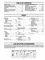
Table of Contents ..................................
Throttle Adjustment .............................
Tires ....................................................
Transporting .................................... 9,
Trouble Shooting Guide ................ 18,
Maintenance Agreement ....................... 4
Maintenance Schedule ........................ 12
Muffler .................................................
15
O
Oil:
Change ...................................... 13, 14
Type ................................................
10
Operating Log Splitter ........................... 9
5
16
17
10
19
W
Warranty ................................................
3
R
Repair/Replacement Parts:
Log Splitter ................................ 20, 21
Engine ........................................
22-27
Reservoir Fluid .............................. 11, 13
Responsibilities, Customer ........ 4, 12-15
,,,,,,,,,,,
m
iiiiiiiiiii
i
iii i
LOG SPLITTER ACCESSORIES
__
I
mile
I
IIIIII I II
I
I
I
IIII
I
ii
,,,,,,,,,
................................................
These accessories were available when the log splitter was purchased. They are aJso available at most Sears
retail outlets, catalog and service centers.
model number of your log splitter.
Spark
Plug
Air Filter
Most Sears stores can order repair pads for you, when you provide the
Muffler
Engine
Oil
ip
_*,
! ._mll
I t.--|
am,,-
5
Gas Can
Stabilizer
........
ASSEMBLY
I
I
IIIIIIIIIIIIIIIIIIIII
IIIIIIII
iiii IIII IIIIIII
INSTRUCTIONS
g
i
liB
mUiR
,,,H
,,,,,,
,,,
,,,,m ,,,,,,,
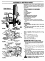
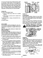
IMPORTANT: This unit has been shipped without
gasoline or oil in the engine. Be certain to service
engine with gasoline and oil before operating your
log splitter.
Wedge, Beam and
Cylinder
TOOLSREQUIREDFORASSEMBLY
(1) Knife
(1) Cutters
(2) 9/16" Wrenches*
(1) Screwdriver
(1) Pliers
*Adjustable Wrenches may be used.
Tongue
and Hitch
Assembly
OTHER MATERIALS REQUIRED
Engine Oil (Provided in Carton)
Unleaded Gasoline
Approximately 7,6 Gallons of Dexron 11Automatic
Transmission Fluid or 10W Non-Foaming Hydraulic
Fluid
Jack
Wheels and
Tank
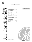
UNPACKING
•
End
Plate
FIGURE 1.
Wedge, Beam and
Cylinder Assembly
Remove staples in top flaps of carton. Remove top
panel.
• Cut carton down along each corner.
down flat. See figure 2.
Lay carton
• Cut and remove
place.
the unit in
the bands
holding
NOTE: All hardware needed for assembly has been
placed in position on the various parts of the log
splitter.
<-PARTS IN CARTON (See figure 2)
Wheels and Reservoir Tank Assembly
Wedge, Beam and Cylinder Assembly
Tongue and Hitch Assembly
Bottle of Engine Oil (Not Shown)
Wheels
Reservoir Tank
Assembly
FIGURE 2.
Tongue and Hitch
Assembly
Tongue and Hitch
Assembly
Wheels and
Reservoir Tank
Assembly
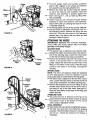
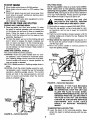
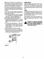
ASSEMBLINGYOUR LOG SPLITTER
•
Remove the hex nuts, lock washers and hex bolts
from the middle of the wheels and reservoir tank
assembly.
•
Place the end of the tongue and hitch assembly in
between the brackets on the wheels and reservoir
tank assembly.
Secure with hardware
just
-',P-----removed. See figure 3.
•
Roll the wheels and reservoir tank assembly off the
packing material.
• Rotate the wedge, beam and cylinder assembly
90 ° so the end plate (refer to figure 1) is off the
wooden pallet. Stand the wedge, beam and
cylinder assembly upright, with cylinder to the top.
Hex Nuts
_
FIGURE 3.
6
ARNING: USE
EXTREME
ASSEMBLY
IS VERY
HEAVY. CAUTION
AS
• Turn the wedge, beam and cylinder assembly
around 180 ° degrees so the wheels and reservoir
tank assembly can be easily attached to it.
• Remove the cotter pin and the hinge pin, located
on top of the reservoir tank assembly. Move the
reservoir tank assembly in position against the
-,i----beam.
See figure 4. Line up holes by lifting hitch
end of assembly,
• Insert hinge pin just removed through welded
brackets on beam and reservoir tank assembly.
Secure with cotter pin, bending the ends of the pin
in opposite directions.
• Tilt the tog splitter and roll off the packing materials.
• The jack stand is attached to the tongue, and is in
the transport position. Remove the spring pin and
clevis pin. Pivot the jack stand to the operating
position (90°), and secure with the clevis pin and
spring pin. Refer to figure 1.
Cotter
Pin
FIGURE 4.
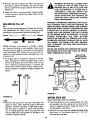
ATTACHING
THEHOSES
IMPORTANT:
REMOVE ANY PLASTIC PROTECTIVE CAPS ON HOSE ENDS AND FITTINGS
BEFORE A1 I'ACHING HOSES.
Pump
Reservoir
Tank
Suction
Hose
FIGURE 5.
Return
Pressure
Hose
Control
Valve
Hose
FIGURE 6.
SUCTION HOSE
• The suction hose is attached to the reservoir tank,
beneath the engine mounting bracket. See figure 5.
Cut off the securing strap. Loosen the hose clamp
on the free end of the hose using a screwdriver.
• Remove the protective cap from the fitting on the
bottom of the pump (some oil may flow from
pump). Attach the end of the suction hose to the
fitting on the bottom of the pump. Place the hose
clamp at the base of the fitting,
and tighten
securely.
RETURN HOSE
NOTE: The return and pressure hoses are protected
by wire hose guards. It may be necessary to push
hose guards back to install hoses to the log splitter.
• The return hose is attached to the top of the control
valve. Loosen the hose clamp on the free end of the
hose using a screwdriver. Cut off the securing strap.
• Remove the protective cap from the fitting on top of
the filter head. Attach the end of the return hose to
the fitting on top of the filter head. See figure 6.
Place the hose clamp at the base of the fitting, and
tighten securely.
PRESSURE HOSE
• The pressure hose is attached to the top of the
pump. Route the hose as shown in figure 6. Secure
the pressure hose to the bottom of the control
valve, using an adjustable wrench.
FINAL ASSEMBLY
• Make certain all hose clamps are tightened securely.
• The tires may have been over-inflated for shipping
purposes. Recommended pressure is between 12
and t5 p.s.i. Check tire pressure and reduce if
necessary.
I
•
II IIIIIIIIIIIII
fillII IIIIIIIIIIIII
I
J
I
I
I a
I I
I aD
I
IIIIIIIIII
OPERATION
lira
,,, ,i,
,,
i
,i
i
m
,,,,,,,,,,,,,,,,,
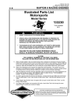
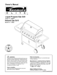
KNOWYOURLOGSPLITTER
READ THiS OWNER'S MANUAL AND SAFETY RULES BEFORE OPERATING YOUR LOG SPLITTER.
Compare the illustrations with your log splitter to familiarize yourself with the location of various controJs and
adjustments, Save this manuat for future reference.
Beam
Fuel
Shut-Off
Valve
Fuel
Spark Plug,
Wire and Boot
Under Cover)
Control
Handle
Locking
Rod
Choke
Fill
rhrottle
Splitting
Switch
Handle
i
Jack
Stand
Reservoir
Starter
Handle
FIGURE 7.
End Plate
]
II IIIIII
]
1111111111111111
I
MEETS ANSI SAFETY REQUIREMENTS
Sears log splitters conform to the safety standard B7! .7-1985 of the American National Standards Institute.
11111
iiiiiiiiiii
OPERATING
CONTROLS(See
ENGINE
engine.
figure 7)
LOCKING
RODSmLocated
on the tongue and
reservoir tank assemblies, They are used to secure
the beam in the horizontal or vertical position.
CHOKE LEVERBUsed to enrich the fuel mixture in
the carburetor when starting a cold engine.
SHUT-OFF
SWITCHmUsed
to stop the
FUEL SHUT-OFF VALVE_Used
fuel into the carburetor.
to stop the flow of
THRO'n'LE CONTROLmPermits
slow engine speed.
selection of fast or
WARNING: NEVER STAND NEXT TO THE
STARTERHANDLE--Used to manuallystart the
engine.
SPLITTING
WEDGE WHEN
OPERATING
THE
LOG SPLITTER.
ALWAYS
STAND
BEHIND THE RESERVOIR TANK.
I
IIIII
II
I
IIIIIIIIII
i iiiiiiiiiiiiiiiiiiiiiii
BEFORE USING YOUR LOG SPLITTER, AGAIN REFER TO THE "SAFETY RULES" AS SHOWN ON PAGE 2
OF THIS MANUAL. ALWAYS BE CAREFUL.
The operation of any log splitter can result in foreign objects being thrown into the
eyes, which can result in severe eye damage. Always wear safety glasses or eye
shields before starting power tool operation or while performing any adjustments or
repairs. We recommend Wide Vision Safety Mask for over spectacles or standard
safety glasses available at Sears Retail or Catalog Stores.
8
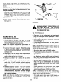
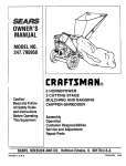
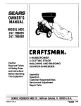
TO STOP ENGINE
SPLITTING WOOD
Use the log splitter only on a level, hard surface.
Never stand next to the splitting wedge when
operating the log splitter. Always stand behind the
reservoir tank. See figures 8 and 9. Never attempt to
cut a log in half sideways. Always split the log lengthwise. Maximum length of log to be split is 24".
• Move throttle control lever to SLOW position.
• Move engine shut-off switch to OFF position. See
figure 7.
• Disconnect spark plug wire and move away from
spark plug to prevent accidental starting while
equipment is unattended.
• Close fuel shut-off valve when equipment is not in
use to prevent fuel leakage,
,A
HOW TO USE YOUR LOG SPLITTER
RAISING AND LOWERING BEAM
• Place log splitter on a firm, level surface. To raise
the beam for vertical operation, pull the locking rod
on the tongue out and pivot it down to release the
beam. Place the beam in the vertical position,
Secure it with the locking rod on the reservoir tank
assembly. See figure 7.
• To lower the beam, pull out on the locking rod and
pivot it down to release the beam, Carefully pull
back on beam and lower it to the horizontal position. Pull the locking rod on the tongue out, pivot it
up and release it to hold the beam. Make certain it
is latched securely.
USING THE CONTROL HANDLE
The control handle has three positions:
FORWARD--Push the control handle down for vertical operation, push it forward for horizontal operation--Splitting wedge moves toward the end plate.
Control handle will return to neutral position as
soon as handle is released.
WARNING:
ALWAYS
USE THE LOG
SPLITTER IN THE VERTICAL POSITION
ONLY WHEN SPLITTING HEAVY LOGS.
Set throttle at maximum speed (3450-3600 RPM).
e Place the log upright, on top of end plate for vertical operation, and on top of beam for horizontal
operation,
Push the control handle to forward position until the
splitting wedge just contacts the log. Release the
control handle.
e Step behind the reservoir tank (see figures 8 or
9) and push the control handle in forward position
until the log is split.
o Move the control handle to reverse position to
return the splitting wedge.
Control
Handk
Splitting
Wedge
End Plate
NEUTRAL (Middle position)--Splitting wedge stops in
place.
REVERSE--Push
the control handle upward for vertical operation, push it toward the rear for horizontal
operationJSptitting
wedge returns. The control
handle will lock in the reverse position, and will
return to neutral automatically when the reverse
stroke is complete.
Reservoir Tank
FIGURE 9.--Horizontal
WARNING:
IF THE FLUID BECOMES
EXCESSIVELY HOT AT ANY TIME DURING OPERATION, STOP THE UNIT AND
ALLOW THE FLUID TO COOL DOWN.
MAXIMUM PERFORMANCE WILL NOT BE
OBTAINED FROM THE LOG SPLITTER IF
THE FLUID IS TOO HOT. USE EXTREME
CAUTION AS CONTACTING SURFACES
CONTAINING
HOT
FLUID
COULD
RESULT
IN SERIOUS
PERSONAL
INJURY.
Reservoi r
Splitting
FIGURE 8.--Vertical
Operation
TRANSPORTING LOG SPLITTER
• Lower the beam to its horizontal position. Make
certain the beam is latched securely with the locking rod.
Operation
9
WARNING: DO NOT FILL CLOSER THAN
1/2 INCH OF TOP OF FUEL TANK TO
PREVENT SPILLS AND TO ALLOW FOR
FUEL EXPANSION.
IF GASOLINE
IS
ACClDENTLY
SPILLED,
MOVE LOG
SPLII'rER AWAY FROM AREA OF SPILL.
AVOID CREATING
ANY SOURCE OF
IGNITION
UNTIL GASOLINE
VAPORS
HAVE DISAPPEARED.
• Remove the quick release pin which secures the
jack stand. Support the tongue, and pivot the jack
stand up against the tongue. Secure with the quick
release pin.
• Attach the hitch to a towing vehicle, making certain
to latch securely. Attach the safety chains to the
towing vehicle.
WARNING: EXPERIENCE INDICATES THAT ALCOHOL BLENDED FUELS (CALLED GASOHOL OR
USING ETHANOL OR METHANOL) CAN AI"IrRACT
MOISTURE WHICH LEADS TO SEPARATION AND
FORMATION
OF ACIDS DURING
STORAGE.
ACIDIC GAS CAN DAMAGE THE FUEL SYSTEM
OF AN ENGINE WHILE IN STORAGE. TO AVOID
ENGINE
PROBLEMS,
THE
FUEL
SYSTEM
SHOULD BE EMPTIED OR TREATED WITH FUEL
STABILIZER
BEFORE STORAGE FOR 30 DAYS
OR LONGER. USE FRESH FUEL NEXT SEASON.
SEE "STORAGE"
SECTION
FOR ADDITIONAL
INFORMATION.
GASAND OIL FILL-UP
OIL
Only use high quality detergent oil rated with API service classification SG. Select the oil's viscosity grade
according to your expected operating temperature.
Colder
<
32°F .....
5W30
_
Warmer
SAE 30
NOTE: Although multi-viscosity oil (5W30, 10W30,
etc.) Improve starting in cold weather, these multiviscosity oils will result in increased oil consumption
when used above 32°F. Check your oil level more frequently to avoid possible engine damage from running low on oil.
NEVER USE ENGINE OR CARBURETOR CLEANER PRODUCTS IN THE FUEL TANK OR PERMANENT DAMAGE MAY OCCUR.
Spark Plug,
Wire and Boot
Fuel
.(Under Cover)
Tank,
• Fill engine with oil as follows. Remove oil fill dipstick. See figure 10. With log splitter level, use a
funnel to fill engine with oil to FULL mark on dipstick. Capacity is approximately
1-1/4 pints. Be
careful not to overfill. Check oil level. Refill to FULL
mark on dipstick if necessary. Replace dipstick and
tighten.
Mufti
Oil
Fill
Dipstick
Oil
Fill
Dipstick
Starter_
Handle
\_
k/_ " /_:'t//
_'__
FIGURE 11.
FIGURE 10.
BEFOREEACHUSE
GAS
Before each use, check the following:
• Remove fuel cap and fill fuel tank with about one
gallon of clean, fresh, lead-free grade automotive
gasoline. DO NOT use Ethyl or high octane gasoline. Be certain container is clean and free from
rust or foreign particles. Never use gasoline that
may be stale from long periods of storage in the
container. Replace fuel cap.
• Place log splitter on a firm, level surface. For vertical operation, putl the locking rod out and pivot it
down to release the beam. Place the beam in the
vertical position, See figure 7.
• Remove the vent plug and check the fluid level,
See figure 12. Fluid level should be 1-1/2" to 2"
from the top of the tank.
10
NOTE: Before initial use or first time use after storage, be certain to fill the reservoir as instructed in next
section.
IMPORTANT:
Reservoir tank must be full as instructed. Low fluid level will damage the pump and
void your warranty.
• Lubricate the beam area where the splitting
wedge will slide with engine oil (DO NOT USE
GREASE). Make certain to oil both front and back
of the beam face.
• Fill fuel tank as instructed previously.
• Attach spark plug wire and cover to spark plug.
See figure 11.
FIGURE 12.
&
WARNING: DO NOT OPERATE THE LOG
SPLITTER
WITHOUT
THE PROPER
AMOUNT OF TRANSMISSION
FLUID IN
THE RESERVOIR TANK.
TOSTARTENGINE
• Open cover (on top of fuel tank) and attach spark
plug wire and rubber boot to spark plug if necessary. See figure 11.
BEFOREINITIAL USE
Fill the reservoir tank as follows.
• Open fuel shut-oft valve by turning in direction of
arrow. See figure t3,
• Remove reservoir vent plug, See figure 12. Using
Dexron II automatic transmission fluid, fill reservoir
to the top. Replace vent plug securely.
• Place the throttle control lever in FAST position.
See figure 13.
NOTE: Total capacity of system is approximately 4
gallons.
NOTE: If the throttle control lever fails to stay in the
desired position or if it is hard to move, refer to the
service and adjustment section.
• Disconnect the spark plug wire. Prime the pump
by pulling the recoil starter, to turn the engine
over, approximately
10 times. Reconnect the
spark plug wire.
• Move choke lever down to CHOKE position.
•
• Start engine. Use the control handle to extend the
wedge to the far extended position. Leave the
wedge in this position (do not retract).
•
Place the engine shut-off switch in ON position.
See figure 13.
• Grasp starter handle (see figure 11) and pull rope
out slowly until engine reaches start of compression cycle (rope will pull slightly harder at this
point). Let the rope rewind slowly.
Refill tank to within 1-1/2" to 2" from the top of the
tank.
• Now retract the wedge. Extend and retract the
wedge fully 10 to 12 complete cycles to remove
trapped air in the system (system is "self-bleeding").
•
Pull rope with a rapid, continuous, full arm stroke,
Keep a firm grip on starter handle. Let rope rewind
slowly. Do not let starter handle snap back against
starter.
• Refill the reservoir to within 1-1/2" to 2" from the
top of the tank. Much of the original fluid has been
drawn into the cylinder and hoses. Make certain to
refill the reservoir, to prevent extreme damage
to the hydraulic pump. Failure to refill the tank
will void your warranty.
•
Repeat preceding two instructions until engine
fires. When engine starts, move choke lever on
engine halfway between CHOKE and RUN.
NOTE; Some fluid may overflow from the vent plug as
the system builds heat and the fluid expands and
seeks its own level.
• Run wedge up and down beam 6 to 8 times to circulate the hydraulic fluid, which will warm and thin
the fluid.
NOTE: If engine does not fire after three attempts,
move choke lever halfway between CHOKE and RUN
position and try again. See figure 13.
11
TO STOPENGINE
On
•
•
Move throttle control lever to SLOW position.
Move engine shut-off switch to OFF position. See
figure 13.
• Disconnect spark plug wire and move away from
spark plug to prevent accidental
starting while
equipment is unattended.
• Close fuel shut-off valve when equipment is not in
use to prevent fuel leakage.
,,,,, ,,
Fuel Shut-Off
Valve
Throttle
....... ,,,
Engine Shut_
Switch
,,,
Choke
"Choke _t_
l_l
Position
CHOKE
FIGURE 13.
III
IIIIIII
IIIIIIIIIIIIIIIIIIII
II
I
CUSTOMER
B/
•
I 1/I
I1[111
IIII
RESPONSIBILITIES
IIIIIIIIIIIIIIIIII
I
I
.........
MAINTENANCE SCHEDULE
FILL IN DATES
AS YOU COMPLETE
REGULAR SERVICE
/
1_
,..'_-/.._-I
.......
/ ,,"/_/,_"/,_/
Check Reservoir Fluid
V
Lubricate Beam and Wedge
q
SERVlCE
DATp
.....
Change Hydraulic Filter
_/
i
Check Engine Oil
V
Change Engine Oil
_t
Service Air Cleaner
Clean Engine
Idl]
q
V
V
, i
Spark Plug
.......,,,,,,,,
_/
Muffler
q
....I
_/ CHECK
12
GENERALRECOMMENDATIONS
&
Hex Bolts
WARNING: ALWAYS STOP THE ENGINE
AND DISCONNECT
THE SPARK PLUG
WIRE BEFORE PERFORMING ANY MAINTENANCE OR ADJUSTMENTS.
Wedge
Plate
Check all nuts, bolts and hose clamps periodically to
make certain they are tightened securely.
LOGSPLITTER
RESERVOIR FLUID
Check the hydraulic fluid level in the log splitter reservoir tank before each use. Fluid level should be 1-1/2"
to 2" from the top of the tank.
Gib
"Back _.
Plate
FIGURE 14.
Change the hydraulic fluid in the reservoir every 100
hours of operation. Disconnect the suction hose from
the bottom of the reservoir tank, and drain the fluid
into a suitable container. Refill using only Dexron II
automatic transmission
fluid, as instructed in the
BEFORE INITIAL USE section of this manual. Also,
make certain to change the hydraulic filter.
Periodically remove and replace the "gibs" (spacers)
between the wedge plate and the back plate as follows.
NOTE: If desired, the gibs may be rotated and/or
turned over for even wear.
•
NOTE: Drain the fluid and flush the reservoir tank and
hoses with kerosene whenever any repair work is performed on the tank, hydraulic
pump or valve.
Contaminants in the fluid will damage the hydraulic
components (should be performed by your SEARS
Service Center).
Remove the center bolt on top of the wedge plate.
Slide the gib plate out. See figure 14.
• Remove and replace the gibs. Reassemble the gib
plate, making certain flat washer is in place under the
gib plate.
• Readjust the bolts on the side of the wedge plate as
instructed previously.
WARNING:
USE EXTREME
CAUTION
WHEN WORKING WITH KEROSENE, AS
IT IS AN EXTREMELY
FLAMMABLE
FLUID.
HYDRAULIC FILTER
Change the hydraulic filter every 50 hours of operation. Use only a 10 micron hydraulic filter. Order part
number 723-0405.
BEAM AND SPLITTING WEDGE
Lubricate both sides of the beam where it contacts the
splitting wedge with engine oil before each use to
obtain years of service. However, normal wear will
occur. Periodically adjust the bolts on the side of the
wedge plate as follows to eliminate the excess space
between the wedge plate and the beam. See figure
14.
ENGINE
ENGINE OIL
Only use high quality detergent oil rated with API service classification SG. Select the oil's viscosity grade
according to your expected operating temperature.
Colder
• Loosen the three hex bolts on top of the wedge
plate (beneath the splitting wedge).
• Loosen the lock nuts on the two adjustment bolts
on the side of the gib plate, located beneath the
splitting wedge. Turn the adjustment bolts in until
snug, then back them off slowly until the wedge
assembly wil! slide on the beam.
<
32°F "'
=
Warmer
NOTE: Although multi-viscosity oil (5E30, 10W30,
etc.) improves starting in cold weather, these multiviscosity oils will result in increased oil consumption
when used above 32 ° F. Check your oil level more
frequently to avoid possible engine damage from running low on oil.
• Tighten the lock nuts securely against the gib plate
to hold the adjustment bolts in this position.
• Retighten the three hex bolts on top of the wedge
plate.
13
Your four-cycle engine will normally consume some
oil; therefore, check engine oil level regularly-approximately
every five hours of operation and
before each usage. Stop engine and wait several
minutes before checking oil level. With engine level,
the oil must be to the FULL mark on dipstick (refer to
figure 11). Change engine oil after the first five hours
of operation, and every twenty-five hours thereafter.
Retainer
Cover
Pre-Cleaner
To Drain Oil:
• Drain oil while engine is warm,
Cover
Screws
a, Remove oil drain plug. Catch oil in a suitable
container.
FIGURE 15.
CLEAN ENGINE
Clean engine periodically. Remove dirt and debris
with a cloth or brush. Cleaning with a forceful spray of
water is not recommended as water could contami-
b. When engine is drained of all oil, replace drain
plug securely.
• Refill with fresh oil. Refer to GAS AND OIL FILLUP section.
nate the fuel system.
• Replace dipstick.
Yearly or every 25 hours, whichever occurs first,
remove the blower housing and clean the areas
shown in figure 16 to avoid overspeeding, overheating
and engine damage. Clean more often if necessary.
AIR CLEANER
WARNING:
The air cleaner prevents damaging dirt, dust, etc.,
from entering the carburetor and being forced into the
engine and is important to engine life and performance.
Never run your engine without
pletely assembled.
To Service Air Cleaner:
,ase
Slot
PERIODICALLY
CLEAN MUF-
FLER AND
AREA
TO REMOVE DEBRIS.
ALL GRASS,
DIRT
COMBUSTIBLE
Clean Out
and
Dirt
air cleaner com-
Service pre-cleaner after every 25 hours of use, or at
least once a season. Service cartridge every 100 hours
of use, or at least once a season. Service pre-cleaner
and cartridge more often under dusty conditions.
• Loosen air cleaner cover screws. Remove cover
and air cleaner assembly from base. See figure 15.
FIGURE 16.
• Remove air cleaner assembly from inside cover
and disassemble.
SPARK PLUG
The spark plug should be cleaned and the gap reset
to .030" at least once a season or every 50 hours of
operation. See figure 17. Spark plug replacement is
recommended at the start of each season. Refer to
engine parts list for correct spark plug type.
• To service foam pre-cleaner: Remove pre-cleaner.
Wash in liquid detergent and water. Squeeze dry in
a clean cloth. Saturate in engine oil. Squeeze in a
clean, absorbent cloth to remove all excess oil. If
pre-cleaner is very dirty, replace it.
NOTE: Do not sandblast spark plug. Spark plug
should be cleaned by scraping or wire brushing and
washing with a commercial solvent.
.030" Feeler Gauge
• To service cartridge: Clean by tapping gently on a
flat surface, tf very dirty, replace. Do not oi! cartridge.
NOTE: Do not use petroleum solvents (e.g. kerosene)
or pressurized air to clean cartridge. They will cause
cartridge to deteriorate.
• Reassemble retainer on pre-cleaner and cartridge
(screen side of pre-cleaner
toward cartridge
pleats). Place assembly into cover.
Spark Plug
• Insert tabs on cover into slots in base and tighten
cover screws securely.
FIGURE 17.
14
MUFFLER
Do not operate the tog splitter without a muffler or
tamper with the exhaust system. Damaged mufflers or
spark arresters could create a fire hazard, inspect
periodically, and replace if necessary. If your engine
is equipped with a spark arrester screen assembly,
remove every 50 hours for cleaning and inspection.
Replace if damaged.
I
IIIIII
.....
ii
IIIIIIIIIIIIIIIIIIIIIIII
llIIIIIIIIIIIIIIIIIIII
1111111111111
IIIII
II
IIII
III
--
STORAGE
I
IIIIIIIIIII
I
......................
Prepare your log splitter for storage at the end of the
season or if the log splitter will not be used for 30
days or more.
_)
ENGINE
IMPORTANT:
IT IS IMPORTANT
TO PREVENT
GUM DEPOSITS FROM FORMING IN ESSENTIAL
FUEL SYSTEM PARTS SUCH AS CARBURETOR,
FUEL FILTER, FUEL HOSE, OR TANK DURING
STORAGE. ALSO, EXPERIENCE INDICATES THAT
ALCOHOL BLENDED FUELS (CALLED GASOHOL
OR USING
ETHANOL
OR METHANOL)
CAN
ATTRACT MOISTURE WHICH LEADS TO SEPARATION AND FORMATION OF ACIDS DURING STORAGE. ACIDIC GAS CAN DAMAGE THE FUEL SYSTEM OF AN ENGINE WHILE IN STORAGE.
• Drain the fuel tank.
• Start the engine and let it run until the fuel lines and
carburetor are empty.
• Never use engine or carburetor cleaner products in
the fuel tank or permanent damage may occur.
• Use fresh fuel next season.
NOTE: Fuel stabilizer is an acceptable alternative in
minimizing the formation of fuet gum deposits during
storage. Add stabilizer to gasoline in fuel tank or storage container. Always follow the mix ratio found on
stabilizer container. Run engine at least 10 minutes
after adding stabilizer to allow the stabilizer to reach
the carburetor. Do not drain the gas tank and carburetor if using fuel stabilizer.
• Drain all the oil from the crankcase (this should be
done after the engine has been operated and is still
warm) and refill the crankcase with fresh oil.
• If you have drained the fuel tank, protect the inside
of the engine as follows. Remove spark plug, pour
approximately 1/2 ounce (approximately one tablespoon) of engine oil into cylinder and crank slowry
to distribute oil. Replace spark plug.
WITH FUEL IN THE FUEL TANK INSIDE
WARNING:
NEVER STORE MACHINE
OF BUILDING
WHERE
FUMES MAY
REACH AN OPEN FLAME OR SPARK, OR
WHERE
IGNITION
SOURCES
ARE
PRESENT SUCH AS HOT WATER AND
SPACE HEATERS, FURNACES, CLOTHES
DRYERS, STOVES, ELECTRIC MOTORS,
ETC.
NOTE: A yearry check-up by your local Sears Service
Center is a good way to make certain your log splitter
will provide maximum performance for the next season.
LOG SPLI'R'ER
• Clean the log splitter thoroughly.
•
Wipe unit with an oiled rag to prevent rust, especially wedge and beam.
• The tongue can be removed and reattached in an
upright position as shown in figure 18 to take less
space when storing.
OTHER
• Do not store gasoline from one season to another.
• Replace your gasoline can if your can starts to rust.
Rust and/or dirt in your gasoline will cause problems.
• Store unit in a clean, dry area.
NOTE: If storing in an unventilated or metal storage
shed, be certain to rustproof the equipment by coating
with a light oil or silicone.
_J
FIGURE 18.
15
iii
ii
i
iii
i iiiii
|
iiiiii
in
SERVICE AND ADJUSTMENTS
, iii
i
iiiiiii
iiii
iii
IIIIIII
FLEXIBLEPUMP COUPLER
i
z=
NOTE: Make certain proper clearance
before tightening set screw.
The flexible pump coupler is a nylon "spider" insert,
located between the pump and engine shaft. Over a
period of time, the coupler wil! harden and deteriorate.
Replacement
is needed if you detect vibration or
noise coming from the area between the engine and
the pump. If the coupler fails completely, you wil!
experience a loss of power. For a replacement tlexible
pump coupler, order part number 717-0891.
•
m
is obtained
Reattach spark plug wire to spark plug.
PUMP
Set Screw
WARNING:
NEVER
HIT THE PUMP
SHAFT IN ANY MANNER, AS ANY BLOW
WILL CAUSE PERMANENT DAMAGE TO
THE PUMP.
Nylon
Insert
When replacing the flexible pump coupling, proceed
as follows. Follow the instructions care|ully as the
alignment is very critical.
piing
Halves
ENGINE
FIGURE 19.--BOTTOM
• Disconnect the spark plug wire from the spark plug,
and secure it away from the spark plug.
VIEW
THROTTLEADJUSTMENT
• Using a 1/2 inch wrench, remove three nuts and
lock washers which secure the pump to the coupling shield. Two nuts are at the bottom corners
and one is in the top center.
To adjust throttle control lever, loosen or tighten wing
nut until throttle control lever moves with some resistance and still remains in desired position when
engine is running. See figure 20.
• Remove the pump.
• Rotate the engine by pulling starter handle until
engine coupling half set screw is at bottom. Loosen
set screw using 7/64 inch Allen wrench. Slide coupling half off of engine shaft.
Throttle
Control.
Lever
• Loosen set screw on pump coupling half, and
remove coupling hail.
Wing
Nut
• Slide new engine coupling half onto the engine
shaft until the end of the shaft is flush with the inner
portion of the coupling half. (There must be space
between end of engine support bracket and coupling half.) Tighten set screw.
• Install pump coupling half and key on pump shaft.
Rotate coupling half until set screw faces down. Do
not tighten set screw.
FIGURE 20.
CARBURETOR
ADJUSTMENT
• Install nylon "spider" onto engine coupling half.
WARNING:
• Align pump coupling half with nylon "spider" by
rotating engine using starter handle. Slide coupling
half into place while guiding three mounting bolts
through holes in pump support bracket.
IF ANY ADJUSTMENTS
ARE
MADE
ENGINE
THE
ENGINE TO
IS THE
RUNNING
(E.G. WHILE
CARBURETOR), KEEP CLEAR OF ALL MOVING
PARTS. BE CAREFUL OF HEATED SURFACES AND MUFFLER.
• Secure with nuts and washers removed earlier.
• Set .010 to .060 inch clearance between the nylon
"spider" and the engine coupling half and moving
pump coupling half as needed. Secure pump coupling half with set screw.
Minor carburetor adjustment may be required to compensate for differences in fuel, temperature, altitude
or load.
16
NOTE: A dirty air cleaner will cause engine to run
rough. Be certain air cleaner is clean and attached to
the carburetor before adjusting carburetor, Do not
make unnecessary adjustments. Factory settings are
satisfactory for most applications and conditions.
ENGINESPEED
Your engine speed has been factory set. Do not
attempt to increase engine speed or it may result in
personal injury, if you believe the engine is running
too fast or too slow, take your log splitter to the
nearest SEARS Service Center for repair and adjustment.
Never attempt to change maximum engine speed. It is
pre-set at the factory and should be changed only by
a qualified service technician who has the necessary
equipment.
TIRES
Recommended operating tire pressure is 12 to 15
p.s.i. (sidewall of tire may give tire manufacturer's recommended pressure). Maximum tire pressure under
any circumstances is 30 p.s.i. Equal tire pressure
should be maintained on all tires.
The carburetor may need re-adjusting if engine lacks
power or does not idle properly. If adjustments are
needed, proceed as follows.
• Close idle mixture valve (see figure 21) clockwise
( _ ) finger tight only. Forcing may cause damage.
Then open 1-1/2 turns counterclockwise ( _ ).
• Start engine and allow to warm for five minutes.
• Move throttle control lever to IDLE position.
• Rotate throttle counterclockwise (v_) and hold
against idle speed adjusting screw. Turn idle speed
adjusting screw unlil engine is running at 1750
RPM
When installing a tire to the rim, be certain rim is
clean and free of rust. Lubricate both the tire and rim
generously. Never inflate to over 30 p.s.i, to seat
beads.
WARNING:
EXCESSIVE
PRESSURE
(OVER 30 p.s.t.) WHEN SEATING BEADS
MAY CAUSE TIRE/RIM ASSEMBLY TO
BURST WITH FORCE SUFFICIENT
TO
CAUSE SERIOUS INJURY.
• Turn idle mixture valve clockwise (f'q) (lean mixture) until engine JUST starts to slow. Then turn it
counterclockwise (('_) (rich mixture) until engine
starts to run unevenly. Set at midpoint between rich
and lean mixture.
• Recheck idle RPM and readjust if necessary.
• Move throttle control lever to FAST position.
Engine should accelerate without hesitation or
sputtering, tf it does not, carburetor should be readjusted, usually to a slightly richer mixture.
Idle
Speed
Screw
idle
Valve
FIGURE 21.
17
I
I
I
I
I
I
IJ
TROUBLE
II
I
IIUIJ
I
SHOOTING
w,,,ll
PROBLEM
CORRECTIVE ACTION
POSSIBLE CAUSE(S )
Engine fails to start
o
o
nun
,,,,,
Engine shut-off switch OFF.
Fuel shut-off valve closed.
Fuel tank empty, or stale fuel.
Spark plug wire disconnected.
Faulty spark plug.
o
o
e
.......,,,,,,,,,,,,,,,
Move switch to ON position.
Open fuel shut-off valve.
Fill tank with clean, fresh fuel.
Connect wire to spark plug.
Clean, adjust gap or replace.
,, ,,,,,,,
Loss of Power; .........
operation erratic
o
0
Connect and tighten spark plug wire.
Move choke lever to OFF position.
Clean fuel line; fill tank with clean fresh
gasoline.
Disconnect fuel line at carburetor to drain fuel
tank. Refill with fresh fuel.
Adjust carburetor or contact your SEARS
Service Center.
Service air cleaner. See Customer
Responsibilities section of this manual.
Spark plug wire loose.
Unit running on CHOKE.
Blocked fuel line or stale fuel.
Water or dirt in fuel system.
o
Carburetor out of adjustment.
O
Dirty air cleaner.
Engine overheats ...........................
• Carburetor not adjusted
properly.
• Engine oil level low.
• Air flow restricted.
Will not split logs
o
O
• Reservoir fluid level low,
o
Adjust carburetor or contact your SEARS
Service Center.
Fill crankcase with proper oil.
Remove blower housing and clean.
Check and fill reservoir tank as instructed
in Operation section of this manual.
NOTE: For repairs beyond the minor adjustments listed above, please contact your nearest SEARS Service Center.
18
............
i iiiiiiiiiiiiiiiiiiii
ii
•
i,i
r
HYDRAULIC TROUBLE
_,,,,i
N
IIIIIIIIIIIIIIII
ii
iiiiiiiiiii,
Jiiiiiiiiiiiiiiii
iiiiiiii
SHOOTING GUIDE
,,,,
/ I I
m
i
==
,,,,,,u,,_
.................
Problem
Corrective Action
Probable Cause(s)
,
,,,,
Cylinder rod will not
move
A
B
C
D
E
F
G
H
Broken driveshaft
Loose shaft coupling
Gear sections damaged
Damaged relief valve
Hydraulic lines blocked
Too little oil to pump
Damaged directional valve
Blocked directional valve
A
B
C
D
E
F
G
H
,,,,,,,,,
Slow cylinder shaft
speed while
extending and
retracting
A Gear sections damaged
B Excessive pump inlet vacuum
C
D
E
F
Slow engine speed
Damaged relief valve
Too little oil to pump
Air in oi_
G Directional valve leaking internally
H .l.nterna.!tydamaged, cylinder
Engine runs but
wood will not split
or wood splits too
slowly
A Small gear section damaged
B Pump check valve leaking
C Excessive pump inlet vacuum
Return unit for authorized repair
Correct engine/pump alignment as necessary
Return unit for authorized repair
Retum directional valve for authorized repair
Flush and clean hydraulic system
Add oil to reservoir
Return unit for authorized repair
Flush and clean hydraulic system; return
unit for authorized repair
A Return unit for authorized repair
B Make certain pump inlet hoses are clear
and unblocked--use short, large
diameter inlet hoses
C Return unit for authorized repair
D Return unit for authorized repair
E Add oil to reservoir
F Add oil, clean reservoir, make certain oil
return tube is below oil level
G Return unit for authorized repair
H Return unit
for authorized repair
,,,,,,,,,,,,,,,,
_
....
G DirectionaJ valve leaking internally
H Overloaded cylinder
I internally damaged cylinder
A Return unit for authorized repair
B Return unit for authorized repair
C Make certain pump inlet hoses are
clear and unblocked; use short, large
diameter inlet hoses
D Adjust valve while using pressure gauge"
E Add oil to reservoir
F Add oil, clean reservoir, make certain oil
return tube is below oil level
G Return unit for authorized repair
H Do not attempt to split wood against the grain
I Return unit for authorized repair
Engine stalls during
sphtting
A L=owhorsepower!weak
B Overloaded cylinder
A Retum unit for authodzed repair
B uo not attempt to split wood against the grain
Engine will not turn
or stalJs under tow
toad conditions
A Engine/pump misalignment
B Frozen or seized pump
C Low horsepowerlweak engine
D Low relief valve setting
E Too little oil to pump
F Air in oil
Leaking pump shaft
seal
engine
_
Hydraulic
lines blocked
Blocked directional
valve
A
B
C
D
E
A
B
C
D
E
Broken driveshaft
Engine/pump misalignment
Gear sections damaged
Poody positioned shaft seal
Plugged oil breather
A
B
C
D
E
*Should be performedby an authorized SEARS Service Center only.
19
Correct alignment as necessary
Return unit for authorized repair
Return unit for authorized repair
Flush and clean hydraulic system
Flush and clean hydraulic system; return
unit for authorized repair
Return unit for authorized repair
Correct alignment as necessary
Return unit for authorized repa=r
Return unit for authorized repair
Make certain reservoir is properly vented
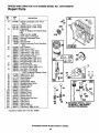
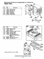
SEARS CRAFTSMAN
5 H.P. LOG SPLITTER
MODEL
NO. 247.346250
Repair Parts
29
/6
35
63
97
96
9
87
39
98
82
\\
20
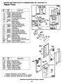
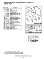
SEARS
CRAFTSMAN
5 H.R LOG SPLITTER
MODEL
NO. 247.346250
Repair Parts
k
KEY
NO.
PART
NO.
1
2
3
4
5
6
7
8
9
10
11
12
13
15
712-0359
714-0162
734-0873
734-1016
734-0872
734-1017
734-0255
736-0351
741-3028
736-0921
737-0192
i737-0238
741-3029
737-0264
736-0192
710-0514
710-1018
16
17
19
710-1032
712-0239
712-3001
21
23
24
25
26
27
28
29
30
3!
32
33
34
35
36
37
38
39
732-0583
781-0323B
781-0537
781-0350A
781-035!
781-0352A
781-0356
714-0203
715-0216
718-0246
7!7-0899
727-0323
781-0526
737-0153
737-0279
737-0235
726-0174
710-0521
40
41
710-0411
710-0944
42
43
44
45
711-0813
712-0375
712-0798
713-0433
DESCRIPTION
KEY
NO.
Slotted Nut 3/4-16 Thd.
Cotter pin 5/32" Dia.
Hub Cap
Wheel Ass'y° Comp.
Tire Only
Rim Only
Air Valve Only
FFWash..76" I.D. x 1.5" O.D,
Bearing Cone
L-Wash. 1/2" I.D.*
90 ° Solid Male Adaptor
Pipe Nipple 1/2 NPT
Bearing Cup
90 ° Male Adapter
FI.Wash..531" I.D. x .94" O.D.
Hex Cap Scr, 3/8-16 x 1" Lg.
Hex Bolt 1/2-20 x 2.75" Lg,
(Grade 8)
Hex Bolt 3/8-24 x 1.5" Lg.
Hex L-Nut 1/2-20 Thd.
Hex Jam Nut 3/8-24 Thd.
(Grade
5) 4' Lg.
!Comp.
Spring
Wedge Ass'y.
Back Plate
Fixed Side Gib
Adiustable Gib
Adjustable Gib Shim
Floating Gib Plate
External Cotter Pin
Cylinder Mounting Pin
Hydraulic Cylinder
Control Valve
Metal Pressure Tube
Hose Guard
Return Elbow
Adapter
3/4" Hose Barb.
Hose Clamp
Hex Bolt 3/8-16 x 3" Lg.
(Grade 8)
Hex Bolt 3/8-16 x 4" Lg.
Hex Bolt 3/8-16 x 4.25" Lg.
(Grade 5)
Clevis Pin 5/t6 x 2.5" Lg.
Hex L-Nut 3/8-16 Thd.
Hex Nut 3/8-16 Thd.
Chain--Tow Hitch
PART
NO.
46
47
49
50
51
52
53
54
55
56
57
58
60
61
62
66
68
73
74
75
76
77
78
79
80
81
82
83
84
85
86
87
88
89
90
91
92
93
95
96
97
98
99
102
103
715-0116
727-0311
736-0116
736-0169
736-0t85
750-0497
781-0162
781-0399
781-0370A
781-0398
723-0405
723-04O6
727-0443
781-0538
681-0014
714-0470
738-0805
710-0117
710-0237
710-0363
712-0123
714-0122
717-0891
718-0249
719-0278
726-0132
727-0451
727-0324
736-0119
781-0097
781-0098
710-0157
710-0409
133402-0011-01
736-0159
737-0236
735-0639
781-0556
681-0011
720-0235
747-0583
732-0194
781-0525
750-0750
721-0168
104
736-0262
770-8766K
*Common Hardware--May be Purchased Locally.
NOTE: Specifications subject to change without notice or obligation.
21
.
...............
DESCRIPTION
Rolt Pin
Hitch Coupler
FI-Wash .635" I.D. x ,93" O.D.
L-Wash. 3/8" I,D,*
FI-Wash..406" I.D. x .75" O.D.
Spacer .44" Lg.
Jack Stand
Tongue Tube
Locking Rod
Beam Support Ass'y.
Filter Element
Filter Head
Return Hose 3/4" I.D. x 44" Lg.
Hose Guard
Vertical Beam Ass'y.
Cotter Pin 1/8" Dia.
Hinge Pin 1/2 x 4.8" Lg.
Hex Bott 5/16-24 x 1" Lg.
Hex Bolt 5/16-24 x .62" Lg.
Hex Bolt 5/16-24 x 4" Lg.
Hex Nut 5/16-24 Thd.
Sq,-Key 3/16" x .75"
Flexible Coupling
Gear Pump
Coupling Shield
Hose Clamp 5/8"
Suction Hose
High Pressure Hydraulic Hose 48
L-Wash. 5/16" I.D.*
Rear Coupling Support Brkt.
Front Coupling Support Brkt.
Hex Bolt 5/16-24 x .75" Lg.
Hex Bolt 5/!6-24 x 1.75" Lg.
Engine---B&S 133402-0011-0t
Fl-Wash. ,344" I.D. x .875" O.D.
L-Vent Pipe Plug
Spark Plug Boot
Fender
Frame Weldment
Grip
Control Handle
Spring Pin
Dis/odger
Spacer 1/2" I.D. x .86" Lg.
Bearing Seal Only
FI-Wash. 3/8" I,D. x .87" O.D.
Owner's Manual
BRIGGS
AND STRATTON
5 H.P. ENGINE
MODEL
NO. 133402-0011-01
614
Repair Parts
- REF.
NO,
PART
1
495133
2
399268
3
"299819
5
214040
7
*272157
8
495774
9
*27549
10
94621
11
66578
13
94221
13A
94167
t4
94679
15
2OO
227
23O
305A
306
307
308
337
383
528
552
562
592
614
616
635
869
870
871
978
979
982
1019
REF.
DESCRIPTION
NO.
94387
223886
494906
94742
94786
224820
94680
224740
802592
89838
231818
231079
92613
231082
93306
231077
66538
211787
211436
262001
*271736
494807
94139
495861
NO.
PART
NO.
75
98A
165
201
209
222
232
284
346
347
663
984
495659
493280
94692
262865
262283
494899
260585
94620
93705
493521
93343
224746
Cylinder Assembly
Bushing-Cylinder
Seal-Oil
Head-Cylinder
Gasket-Cylinder Head
Breather-Valve Chamber
Gasket-Valve Cover
Screw-Breather Mtg.
Grommet-Breather Tube
Screw-Cylinder Head (2-5/16" Long;
Stud-Cylinder Head
Screw-Cylinder Head
(2-15/32" Long)
Plug-Pipe, 1/4" Std., Square Head
Guide-Air
Lever Assy.-Governor
Washer-Governor Lever
Screw-Hex.Hd.
Shield-Cylinder
Screw-Cylinder Shield
Cover-Cylinder Head
Plug-Spark
Wrench-Spark Plug
Tube-Breather
Bushing-Governor Crank
Bolt-Governor Lever
Nut-Hex.
Cotter-Pin
Crank-Governor
Elbow-Spark Plug
Seat-Intake Valve
Seat-Exhaust Valve (Cobalite ®)
Guide-Exhaust Valve
Note: 63709 Guide-Intake Valve
Gasket-Cover
Cover-Oil Gard ®
Screw-Oil GarcP Cover
Label Kit
5
10
;06
I
305A
200
15
I ! 019 LABEL
KIT I "k ToREQUIRESINsTALLSPECIAL
TOOLSsEE
REPAIR
INSTRUCTION
MANUAL,
984
DESCRIPTION
Washer Kit
Screw Assy.-Speed Adj.
Nut-Wing
Link-Governor
Spring-Governor
Plate-Gov. Control
Spring-Link
Screw-Hex. Hd.
Screw-Sere
Switch-Rocker
Screw-Sem
Bracket-Indicator Light
*included in Gasket Set--Part
307
No. 495661.
Assemblies include all parts shown in frames.
22
BRIGGS
AND STRATTON
5 H.P. ENGINE
MODEL NO. 133412-0059-01
Repair Parts
REF.
NO.
PART
NO,
12
*270080
16
*270125
*270126
397103
18
19
20
21
22
494044
495660
294606
66768
94682
24
25
222698
393819
393820
393821
393822
399O67
399014
399015
399O16
26O26
298909
298908
299430
390459
26
27
28
29
30
32
33
34
35
36
40
45
46
219
220
284
441
523
524
525
741
842
847
221890
94745
211119
261044
260552
26478
93312
260642
212733
494845
221551
94620
224240
494416
*271485
280578
262992
*270920
494417
DESCRIPTION
Gasket-Crankcase (.015" Thick,
Std,)
Gasket-Crkcse, (.005" Thick)
Gasket-Crkcse, (.009" Thick)
Crankshaft
Note: To Replace Crankshaft Gear
Key.
Order Part No. 94388.
Cover Ass'y.-Crankcase
Bushing-Crankcase Cover
Seal-Oi!
Ptug-Oil Filler
Screw-Crankcase Cover Mounting
Sere
Key-Flywheel
Piston Ass'y, (Std,)
Piston Ass'y. (.010" O,S.)
Piston Ass'y, (,020" O.S,)
Piston Ass'y. (.030" O.S.)
Ring Set-Piston (Std.)
Ring Set-Piston (.010" O,S.)
Ring Set-Piston (.020" O,S.)
Ring Set-Piston (.030" O.S.)
Lock-Piston Pin
Pin Ass'y,-Piston (Std,)
Pin Ass'y.-Piston (.005" O,S.)
Rod Ass'y.-Connecting
Rod Ass'y.-Connecting
(.020" Undersize Crankpin Bore)
Dipper-Conn. Rod
Screw-Conn. Rod
Valve-Exhaust
Valve-Intake
Spring-Intake Valve
Spring-Exhaust Valve
Retainer-Spring
Tappet-Valve
Gear-Cam
Gear-Governor
Washer-Thrust
Screw-Hex. Hd.
Bracket-Oil Fill
Dipstick and Cap Ass'y.
Sea!-Oil Fill
Tube-Oil Fill
Gear-Timing
Seal-Oil Fill Cap
Tube Ass'y.-High Oil Fill
*Included in Gasket Set--Part
22O
26
27
0524
40
40
lk REQUIRES SPECIAL TOOLS
TO INSTALL. SEE REPAIR
INSTRUCTION MANUAL
No. 495661.
Assemblies include all parts shown in frames.
23
BRIGGS
AND STRA'rroN
5 H.R ENGINE
MODEL
NO. 133402-0011-01
Repair Parts
iiiii
REF.
NO.
PART
NO.
51
52
53
95
98
104
108
111
116
*272295
*272585
94706
94098
398185
118
124
125
127
130
131
133
134
137
141
164
611
634
634A
955
975
,493765
94681
495652
e
224783
262820
°#
223470
493556
398187
°398188
495651
281247
494451
oO
497434
493640
LI
DESCRtPTION
÷
Gasket-Carburetor Mtg.
Gasket- Intake Port
Screw-Adapter Mtg,
Screw-Round Head
Screw-idle Adjusting
Pin-Hinge (Sotd in Kit Only).
Valve-Choke
Spring-Lever
Gasket-Sealing
(Sold in Kit Only).
Valve and Spring-Needle
Screw-Hex. Washer Head
Carburetor Assembly
Plug-Welch
Valve-Throttle
Shaft and Lever-Throttle
Float Assembly-Carburetor
Valve-Inlet (Includes Seat)
Gasket-Bowl (Sold in Kit Only).
Shaft-Choke
Manifold-Intake
Elbow-Fuel Pipe
Seal-Shaft (Sold in Kit Only),
Seal-Choke Shaft (Sold in Kit Only).
Screw-Fuel Bowl
Bowl Assembly-Carburetor
634A
634
111
130
95
611
_24
53
642
96__
REF.
NO.
PART
NO,
159
445
535
642
843
966
969
971
280871
494511
495246
281188
280149
494902
94120
94727
116__
DESCRIPTION
Support-FUter
Fitter-Air Cleaner
Element-Air Cleaner
Cover-Air Cleaner
Sleeve-Lever
Base-Air Cleaner
Screw-Hex.Head
Screw-Hex.Head
445
* Included in Gasket SetmPart No. 495661.
° Included in Carburetor Overhaul KitmPart No. 493762.
_1,Included in Carburetor Gasket Set--Part No. 490937.
Assemblies include all parts shown in frames.
24
535
[I
_
159
BRIGGS
AND STRATTON
5 H.P. ENGINE
MODEL
NO. 133402-0011-01
Repair Parts
REF.
NO.
54
284
3OO
613
832
864
883
REF.
NO.
PART
NO,
94705
94620
494562
94729
494903
494904
*272309
PART
NO.
182
184
185
187
187A
188
429
601
224709
93559
94010
393815
495218
94357
281190
93053
957
958
972
493988
494539
495345
832
..........................
DESCRIPTION
Screw'Hex.Head
Screw-Hex. Hd.
Muffler-Exhaust
Screw-Sem
Guard-Muffler
Flange-Muffler
Gasket-Exhaust
429
DESCRIPTION
Bracket-Fuel Tank
Screw-Hex. Hd.
Nut-Hex.
Line-Fuel (11" Long, Cut to Suit)
Pipe-Fuel (Molded)
Screw-Hex. Head
Cover-Spark Plug
Clamp-Fuel Pipe (Green)
Note: 93807 Clamp-Fuel Pipe
(Black)
Cap-Fuel Tank
Valve Ass'y.-Fuel Shut-Off
Tank Ass'y.-Fuel
182
@
185
*Included in Gasket Set--Part
No. 495661.
Assemblies include all parts shown in frames.
25
'%188
BRIGGS
AND STRATTON
5 H.P. ENGINE
MODEL
NO. 133402-0011-01
Repair Parts
REF,
NO.
PART
NO.
55
56
57
58
494846
493824
262594
280406
59
60
65
69
69A
456
459
461
515
6O8
1016
396892
393152
94686
280973
224322
224321
492833
262626
262625
494782
224278
DESCRIPTION
Housing-Rewind Starter
Pulley-Rewind Starter
Spring-Rewind Starter
Rope-Rewind Starter
(Cut to Required Length)
Insert-Starter Handle
Handle-Rewind Starter
Screw-Starter Mtg.
Washer-Rewind Starter
Washer-Rewind Starter
Retainer-Rewind Starter
Pawi-Starter
Pin-Starter
Spring-Torsion
Starter Ass'y.- Rewind
Cover-Rewind Starter
461
,.-J
69A_
55
65
REF.
NO.
PART
NO.
23
37
73
284
304
305
332
333
335
356
356A
297229
222443
224633
94620
494790
94786
92284
397358
93414
495135
495118
363
455
851
19069
494770
493880
73
305
DESCRIPTION
Flywheel-Magneto
Guard-Flywheel
Screen-Rotating
Screw-Hex.Head
Housing-Blower (Red)
Screw-Blower Housing Mounting
Nut-Flywheel
Armature Group
Screw-Armature Mounting Sem
Wire Assembly (Armature to Switch
Wire Assembly (Stop Switch to
Ground)
Puller-Flywheel
Hub-Starter
Cable Terminal-Ignition
455
23
304
332
284
335
363
356
Assemblies include all parts shown in frames.
26
BRIGGS
AND STRATrON
5 H.P. ENGINE
MODEL
NO. 133402-0011-01
Repair Parts
REF.
NO,
3
7
9
12
PART
NO.
*299819
*272157
*27549
*270080
*270125
*270126
*495307
*272295
*272585
2O
51
52
o
104
116
o_
118
•493765
121
493762
!27
134
•398188
137
358
495661
524
*271485
634
634A i "t
8421 *270920
883
*272309
977
490937
978
*271736
12
............................
DESCRIPTION
Seal-Oil
Gasket-Cylinder Head
Gasket-Valve Cover
Gasket-Crankcase
(.015" Thick, Standard)
Gasket-Crankcase (.005" Thick)
Gasket-Crankcase (.009" Thick)
Seal-Oil
Gasket-Carburetor Mtg.
Gasket-Intake Port
Pin-Hinge (Sold in Kit Only).
Gasket-Seating (Sold in Kit Only).
Valve and Spring-Needle
Carburetor Overhaul Kit
Plug-Welch
Valve-Inlet (Includes Seat)
Gasket-Bowl (Sold in Kit Only).
Gasket Set
Seal-Oil Fill
Seal-Shaft (Sold in Kit Only),
Seal-Choke Shaft (Sold in Kit Only).
Seal-Oil Fill Cap
Gasket-Exhaust
Gasket Set-Carburetor
Gasket-Cover
_978
52
842
883
o 524
2O
,,,,, 111111
iiiiii
] 358 GASKET
i
iiitl
II
iiiii1_111_
ii
SET
I
i
<3 @
104
127
134
116
634A
121 CARBURETOR
,,i
oVERHAUL
iiinl
@
,,,,,,i
116
634A_
137
@ 634
" 977 CARBUR_OR
GASKET
* Included in Gasket Set--Part No. 495661.
• Included in Carburetor Overhaul Kit--Pad No. 493762,
<I, Included in Carburetor Gasket Set--Pad No, 490937.
Assemblies include all parts shown in frames.
27
634
SET
KIT
CRRFTSMRN
OWNER'S
MANUAL
MODELNO.
247.346250
5 HORSEPOWER
25.5 TON
HYDRAULIC LOG SPLITTER
Each log splitter has its own model
has its own model number.
number.
Each
engine
The model number for your log splitter will be found
label attached to the frame.
on a
The model number for the engine will be found on the
blower housing o| the engine adjacent to the spark plug.
All parts listed herein may be ordered
through
Sears,
Roebuck and Co. Service Centers and most Retail Stores.
HOWTOORDER
REPAIRPARTS
WHEN ORDERING
REPAIR PARTS, ALWAYS
FOLLOWING
INFORMATION:
* PRODUCT
- "25.5 Ton Hydraulic
* MODEL
NUMBER
* ENGINE
MODEL
GIVE THE
Log Splitter"
- 247.346250
NO. - 133402-0011-01
* PART NUMBER
* PART DESCRIPTION
"Your Sears merchandise
has added value when you consider that Sears has service units nationwide
staffed with
Sears trained technicians...professional
technicians
specifically trained on Sears products, having the parts, tools and
equipment
to insure that we meet our pledge to you...we
service what we sell."
SEARS, ROEBUCK
770-8766K
8/94
AND CO., Chicago, IL
60684
U.S.A.
Printed In U.S.A.