1
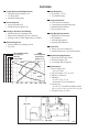
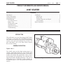
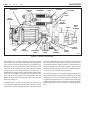
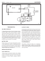
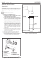
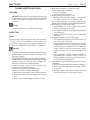
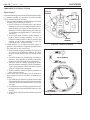
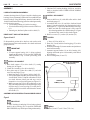
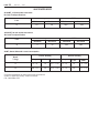
1M-128
PR
ODUCT INF
ORMA
TION
PRODUCT
INFORMA
ORMATION
1/98
28 MT
MEDIUM DUTY
STARTER
SERVICE MANUAL
©1998 Delco Remy International Inc. All Rights Reserved.
PAGE
1M-128
4/96
n Totally-Enclosed Shift Mechanism
l
l
l
n Gear Reduction
Solenoid-Operated Shift Lever
"O" Ring Seals
Solenoid Sealing Boot
l
l
l
l
Layered Wound Coil
Waffle Design Contact Face
l
l
l
n Bearing Lubrication and Sealing
l
l
l
l
l
l
l
l
Positive-Shift Overrunning Clutch
Five Roll
l
28-MT
Cranking Motor
Performance
(@12V, 25°C)
6 30 12 3.0
l
l
l
3 15 6 1.5
Volts
l
2 10 4 1.0
l
Speed
5 2
.5
0
0 0
0
0
Diesel Powered Light Trucks
Diesel Passenger Cars
Low-Range Diesel Engines
n Specifications
4 20 8 2.0
1
Nomex Covered Conductors
Insulated Between Coils and Pole Shoes
n Medium-Duty Applications
l
Watts
5 25 10 2.5
Molded Bar Commutator
Steel Banded
Varnish Impregnated
Dynamically Balanced
n Field Coils
l
Speed (RPM X 1000)
Torque (lb-ft)
Volts (V)
Output (KW)
Four One-Piece Brushes
Constant Pressure Brush Springs
Radialine Brush Holders
Heavy Brush Leads
n High Reliability Armature
Ball Bearing at Commutator End
Bronze Sleeve Bushing in Drive Housing
Sealing for Wet Clutch Applications Available
n Medium-Duty Drive
l
Gear Ratio: 3.875/1
Two Ball Bearings
n Long-Life Brushes
n Sealed Solenoid
l
28-MT STARTER
FEATURES
l
28-5108
200
400
600
800
1000 1200 1400
l
l
Diesel Engine Size:
- Up to 6.5 liters
System Voltage: 12-V or 24-V
Rotation: Clockwise
Mounting:
- S.A.E. #1, #2, #3, #4
- Automotive Type: Pad Mount
Pinion Data
- S.A.E.: No. Teeth/Pinion Blank: (Pitch)
10/11 (10-12); 10/11 (8-10); 12/13 (8-10)
Weight: 8.0 kg (17.6 lbs.)
180.0 mm
338.3 mm
28-5109
28-MT STARTER
1M/128
4/96
PAGE
1
PRODUCT INFORMATION AND SERVICE MANUAL
28-MT STARTER
CONTENTS
Introduction ............................................................... 1
General Description .................................................. 1
Operating Principles ................................................. 3
Troubleshooting ........................................................ 4
On-Vehicle Service .............................................. 4
Battery Tests ........................................................ 4
Wiring and Switches ............................................ 4
Starter Removal ................................................... 4
Starter No-Load Test ........................................... 5
Troubleshooting ................................................... 6
Unit Repair ................................................................ 8
Introduction .......................................................... 8
Disassembly ......................................................... 8
Cleaning, Inspection and Repair .......................... 13
Unit Assembly ..................................................... 16
Starter Installation ..................................................... 19
INTRODUCTION
This publication covers the Delco Remy 28-MT Starter
(see Figure 1). As listed in the CONTENTS, descriptive
information and instructions for testing, troubleshooting,
removal, unit repair and installation are provided. For
parts information, refer to the Delco Remy America
Service Parts Catalog.
GENERAL DESCRIPTION
Figures 1 and 2
The 28-MT starter provides high starting torque in a
compact, lightweight package by using a high speed
motor through an offset gear reduction unit. The 28-MT is
suitable for medium duty applications such as dieselpowered light trucks and passenger cars, and other lowrange diesel engines. Weighing just 8 kg (17.6 lb.), the 28MT produces up to 3 kilowatts of output. Models are
available for either 12- or 24-volt systems, with clockwise
rotation.
28-5107
Figure 1. 28-MT Starter
PAGE
2
1M-128
ARMATURE
28-MT STARTER
4/96
SOLENOID
CONTACT
DISC
SOLENOID
ASSEMBLY
PLUNGER
SPRING
SEALING
BOOT
SOLENOID
PLUNGER
SHIFT
LEVER
BALL
BEARING
CLUTCH
DRIVE
ASSEMBLY
PINION
FIELD
COIL
BALL
BEARING
DRIVE
END
BUSHING
DRIVE
COLLAR
ARMATURE
GEAR
INTERNAL
GEAR
BALL
BEARING
DRIVE
SHAFT
28-5105
Figure 2. Starter Cross Section
The 28-MT has a totally enclosed, solenoid operated
mechanism for positive shift of the pinion into engagement.
The solenoid is sealed to prevent entry of foreign material.
Within the solenoid, waffle-type contact faces and a solid
link between the contact disc assembly and the solenoid
plunger help prevent contact sticking. The shift lever is
attached to the plunger on one end and mates with a collar
on the drive assembly at the other end. The action of the
lever forces the drive pinion into engagement with the
engine flywheel when the magnetic pull of the solenoid
draws the plunger in.
A medium-duty, 5-roll overrunning drive is used for low
overrun friction and long operating life. The drive shaft is
supported by a ball bearing at the gear reduction end and
by a sleeve bushing at the drive end. An external helical
spline on the drive shaft turns the pinion as it moves into
engagement with the engine flywheel. An internal gear at
the gear reduction end of the drive shaft is driven by the
armature shaft gear at a speed of one drive shaft revolution
for each 3.875 revolutions of the armature.
The 28-MT armature is dynamically balanced and rides in
sealed ball bearings at each end. Steel banding and varnish
impregnation are used for added armature strength. The
molded-bar commutator receives electrical power through
radially positioned, one-piece brushes. Constant-pressure
brush springs are used for even brush wear and long brush
life.
28-MT STARTER
1M/128
OPERATING PRINCIPLES
When the engine starts and picks up speed, the overrunning
clutch allows the pinion to spin freely on the starter drive
shaft, preventing the engine from "driving" the starter.
When the start switch is released, current momentarily
flows from the solenoid contacts through the pull-in coil
and hold-in coil to ground. The current flow through the
pull-in coil is in the opposite direction to that in the holdin coil. This creates opposing magnetic fields that cancel
each other out. With the magnetic pull of the solenoid
cancelled, the plunger is released and the plunger spring
pushes it out of the solenoid, opening the solenoid contacts.
The shift lever pulls the pinion out of engagement with the
flywheel.
Figures 2, 3, and 4
Figure 3 shows an electrical schematic for the starter when
it is at rest and when it is cranking the engine. The starter
is at rest when the engine is off and also when the engine
is running normally after starting.
When the start switch is closed, a small current flows
through the solenoid pull-in coil, field coil, and armature
windings to ground. A small current also flows through
the hold-in coil to ground. With both solenoid coils
energized, the plunger is pulled magnetically into the
solenoid. This action moves the shift lever and engages
the pinion with the engine ring gear, and moves the
contact disc to close the solenoid switch contacts. When
the switch contacts close, a large current flows through the
field coils and armature, causing the armature to turn and
crank the engine. This large current heats up the current
carrying conductors in the motor.
Figure 4 shows a typical wiring circuit with the starter
installed on the vehicle. One or more control switches may
be used in series with the start switch to prevent cranking
the engine unless certain system conditions are met. Refer
to the specific vehicle wiring diagram to see what other
cranking controls may be used. A typical example of a
control switch is a neutral safety switch that prevents
cranking unless the transmission is in neutral. In 12-volt
systems, the relatively low current in the "S" terminal
circuit may be handled directly by the start switch. However,
higher current levels in 24-volt systems always require that
the start switch operate a separate magnetic switch in the
"S" terminal circuit.
NOTICE: To avoid damage to the motor due to
overheating, do not crank the engine continuously
for more than 30 seconds at a time. If the engine has
not started within 30 seconds, allow the starter to cool
for at least 2 minutes before trying again.
START
SWITCH
SOLENOID
PLUNGER
SOLENOID
PLUNGER
SOLENOID
HOLD-IN
COIL
SHIFT
LEVER
SOLENOID
PULL-IN
COIL
START
SWITCH
SOLENOID
HOLD-IN
COIL
ENGINE
FLYWHEEL
SHIFT
LEVER
B
BATTERY
SOLENOID
PULL-IN
COIL
B
+
M
BATTERY +
M
-
-
SOLENOID
SWITCH
ENGINE
FLYWHEEL
CLUTCH
DRIVE
ASSEMBLY
AT REST
3
PAGE
4/96
SOLENOID
SWITCH
FIELD
COIL
FIELD
COIL
ARMATURE
ARMATURE
DURING
CRANKING
28-5105
Figure 3. Starter Electrical Schematic
PAGE
4
1M-128
28-MT STARTER
4/96
START
SWITCH
BATTERY
CONTROL
SWITCH
SOLENOID
BAT.
S
M
STARTER
28-5111
Figure 4. Starter Wiring Circuit
TROUBLESHOOTING
ON-VEHICLE SERVICE
To independently test the starter it is necessary to remove
it from the engine. However, before doing this, checks
should be made to ensure that the problem is with the
starter and not with the engine, battery, wiring or switches.
When the other possible problem sources have been
eliminated, then remove and test the starter. Comparison
of test results with the Troubleshooting Chart, Table 1, will
aid in isolating the problem within the starter to specific
components. This will determine the repair or repairs
needed to restore the starter to serviceability.
BATTERY TEST
Realistic testing, as well as successful operation, requires
a fully charged battery capable of supplying the current
needs of the starting system. Step one in troubleshooting
the starting system is to test the battery. Follow vehicle or
battery manufacturer's instructions, such as Delco Remy
America bulletins 1B-115 and 1B-116.
WIRING AND SWITCHES
VISUAL INSPECTION
Visually inspect all wiring and switches in the starting
circuit for damage and loose or corroded connections. This
includes all ground connections. Clean and tighten
connections as required. Replace damaged wiring or
components.
CONTINUITY CHECK
Set parking brake and/or block wheels to prevent movement
of vehicle during checks. Disconnect field lead on starter
from solenoid "M" terminal and insulate carefully to
prevent accidental contact. Set manual transmission to
neutral and depress clutch, or place automatic transmission
in "Park." Use voltmeter to check for voltage at solenoid
"S" terminal while start switch is held in "Start " position.
If voltage is not present at "S" terminal, use voltmeter and
vehicle manufacturer's wiring diagram to trace control
circuit and locate point of voltage loss and correct as
necessary. For further information on general diagnosis of
starter control circuit, refer to Delco Remy America
publication DRA/DP-1029.
STARTER REMOVAL
If the battery, wiring and switches are in satisfactory
condition and the engine is known to be functioning
properly, remove the starter for further testing. Refer to the
vehicle or engine manufacturer's instructions for the proper
removal procedure.
28-MT STARTER
1M/128
STARTER NO-LOAD TEST
GENERAL INFORMATION
With the starter removed from the engine, the no-load test
can reveal damage that can be corrected by repair or it may
indicate the need for component testing after the starter is
disassembled. Repair and component test procedures are
described in the UNIT REPAIR section. The no-load test
is also used to test units for normal operation after repair
or overhaul. Comparison of test results with the
Troubleshooting Chart, Table 1, will indicate what
corrective action, if any, is required
TEST HOOK UP
4/96
PAGE
5
5. As the last step in making the test connection, ground
the negative battery cable securely to a clean metal
ground on the starter frame.
6. The carbon pile load is used to adjust operating
voltage for comparison with specifications. It may
not be necessary in all cases but should be used to
eliminate the need for interpolation of test data.
TEST PROCEDURE
CAUTION: Keep fingers and tools away from
opening in D.E. (drive end) housing while
testing. The strong shifting action of the
solenoid could cause personal injury or
damage as the drive pinion moves into the
cranking position and spins.
Figure 5
NOTICE: During no-load test, close switch and operate
Connect the starter for the no-load test as shown in Figure
5 using suitable instruments, battery cables and connecting
wiring. Note the following.
1. Secure starter in suitable test stand to check operation.
2. Use a momentary contact, pushbutton switch in the
test circuit for quick release if very high current
surges are encountered.
3. Make all connections or disconnections with the
switch open and the carbon pile load turned off.
4. If sparking or current flow in the battery circuit is
noted when making connections, the starter solenoid
switch contacts may be frozen shut (refer to Table 1,
Troubleshooting).
starter for cycles of 30 seconds maximum. Between
cycles, allow starter to cool for at least two minutes.
Otherwise, overheating and damage to the starter may
result.
VOLTMETER
CLAMP ON
AMMETER
BATTERY
SWITCH
A
SOLENOID
BAT.
S
M
CARBON
PILE
R.P.M.
INDICATOR
STARTER
28-5112
Figure 5. Starter No-Load Test Hook-Up
PAGE
6
1M-128
28-MT STARTER
4/96
1. Momentarily close switch.
l If there is high current flow and starter fails to
operate (zero rpm), release switch immediately.
Internal mechanical damage is indicated.
Discontinue test and refer to Table 1,
Troubleshooting.
l If there is no current flow and starter fails to operate
(zero rpm), release switch immediately. An open
circuit is indicated. Discontinue test and refer to
Table 1, Troubleshooting.
l If there is current flow and starter operates, release
switch and proceed with the next step of the noload test.
2. Close switch and observe voltmeter. Adjust carbon
pile load to obtain 10 volt reading (20 volts on 24-volt
starter). Observe and record ammeter and RPM
readings. Release switch.
3. Compare ammeter and RPM readings to those listed
under "Specifications" at the end of this manual. If the
readings are outside the limits shown, refer to Table
1 to determine the most likely causes. If the readings
are within the limits, the starter is operating normally.
TROUBLESHOOTING
If results of the no-load test are outside limits, refer to
Table 1, Troubleshooting for probable cause and correction.
The conditions listed in the table apply specifically to the
no-load test and do not necessarily apply to operation
under other circumstances.
28-MT STARTER
1M/128
4/96
PAGE
7
Table 1. Troubleshooting
CONDITION
PROBABLE CAUSE
CORRECTION*
Normal current and speed
a. Starter OK
a. Recheck battery, switches and
wiring, including battery cable loss
check if starter operation on engine
is slow or sluggish
Current flow with test circuit switch
open
a. Solenoid switch contacts stuck
closed
a. Test and, if necessary, replace
solenoid assembly
Failure to operate with very low or
no current
a. Open solenoid winding
a. Inspect and test solenoid
assembly
b. Open field circuit
b. Inspect and test frame and field
assembly
c. Open armature coil(s) or high
insulation between commutator bars
c. Inspect armature
d. Broken brush spring(s) or worn
brushes
d. Inspect brushes and brush springs
a. Frozen bearing or other damage
to drive train
a. Inspect bearings, armature, drive
shaft and related drive parts
b. Direct ground in terminals or
fields
b. Inspect and test frame and field
assembly, solenoid assembly,
armature and brush installations for
shorts
a. Excessive friction in bearing(s) or
gear reduction unit, bent armature
shaft or loose pole shoe, bent drive
shaft
a. Inspect bearing, armature, drive
shaft, and gear reduction gears
b. Shorted armature
b. Inspect and test armature
c. Grounded armature or fields
c. Inspect and test frame and field
coil assembly and armature
a. High internal electrical resistance
caused by poor connections,
defective leads or dirty commutator
a. Inspect internal wiring, electrical
connections and armature
commutator
b. Causes listed under "Failure to
operate with no current"
b. Corrections listed under "Failure
to operate with no current"
a. Shorted fields
a. Inspect and test field and frame
assembly
Failure to operate with high current
Low speed with high current
Low speed with normal (or low)
current
High speed with high current
*Refer to UNIT REPAIR section for required disassembly, inspection, test and, if necessary repair or replacement instructions.
PAGE
8
1M-128
28-MT STARTER
4/96
UNIT REPAIR
NOTICE: Always install fasteners at original location.
If necessary to replace fasteners, use only correct part
number or equivalent. If correct part number is not
available use only a fastener of equal size and strength
(refer to Delco Remy America Standard Hardware
Fasteners section in Service Parts Catalog). Use a
torque wrench to tighten fasteners when a torque
value is specified in these instructions or in the
vehicle or engine manufacturer's instructions. Torques
specified are for dry, unlubricated fasteners unless
otherwise specified.
INTRODUCTION
UNIT DISASSEMBLY
Figure 7
REMOVE OR DISCONNECT
1. Motor lead on frame, field and brush holder group (A)
from solenoid assembly (1). Reinstall nut on solenoid
terminal.
l Remove nut on solenoid, slip off motor lead and
reinstall nut.
2. Thru bolts (41).
3. Brush plate screws (42).
4. C.E. frame (14) and O-ring (20).
IMPORTANT
Figure 6
In the following step, use care not to loose the small
dowel pin (28) installed between frame, field and
brush holder group (A) and gear reduction and
drive group (B). Dowel pin is required for assembly
and must be saved. If dowel pin should be lost, it
must be replaced with 2 mm (0.079 in.) dia. x 10
mm (0.394 in.) long pin procured or manufactured
locally.
5. Frame, field and brush holder group (A), dowel pin
(28) and frame seal (33).
l Armature assembly (13)
may come off with
frame, field and brush holder group (A) or may be
retained by gear reduction and drive group (B).
6. Armature assembly (13) with bearings (8 and 9).
l Do not remove bearings from armature assembly
unless replacement is required (refer to
CLEANING, INSPECTION AND REPAIR).
7. Solenoid screws (25).
8. Solenoid assembly (1).
l Pivot inside end of solenoid assembly (1) out of
engagement with shift lever in gear reduction and
drive group (B) and withdraw solenoid assembly.
l
Figure 6 illustrates the starter broken down into component
parts and assemblies. Index numbers on Figure 6 correspond
to those used in the Delco Remy America Service Parts
Catalog. Do no attempt to disassemble the following
components which are serviced as assemblies:
solenoid assembly (1)
clutch drive assembly (2)
brush holder assembly (3)
armature assembly (13)
frame and field assembly (19)
This section provides instructions for complete disassembly
of the starter as would be the case for overhaul. If the starter
is not due for overhaul, and repair affecting specific parts
only is required, the starter may be disassembled only to
the extent necessary to gain access to these parts. Parts
removed from the starter as subassemblies or groups need
not be disassembled for such limited repair unless they
contain the affected parts. Total disassembly is
recommended however, to ensure that all parts can be
thoroughly cleaned and inspected.
In this section the starter is broken down by main groups.
These groups are then disassembled into individual parts
and assemblies. Illustrations accompany the text to show
specific operations. To see the parts relationship of the
complete starter, refer back to Figure 6.
DISASSEMBLY
Make a mark completely down one side of the starter to
ensure proper alignment of all components at assembly.
Use a colored pencil or marker that will show on all parts.
Disassemble as follows:
28-MT STARTER
1M/128
41
PAGE
4/96
42
14
20
9
4
3
5
13
29
8
19
28
33
25
39
1
37
5
29
39 4
7
11
36
27 26
16
30
31 32
12
15
1. SOLENOID ASSEMBLY
2. CLUTCH DRIVE
ASSEMBLY
3. BRUSH HOLDER
ASSEMBLY
4. BRUSH (GROUNDED)
5. BRUSH (INSULATED)
6. D.E. HOUSING
BUSHING
7. BRUSH SPRING
8. D.E. ARMATURE
BEARING
9. C.E. ARMATURE
BEARING
10. CENTER SUPPORT
BEARING
11. SHIFT LEVER
12. PINION STOP
13. ARMATURE
14. C.E. FRAME
15. DRIVE SHAFT
16. ARMATURE SUPPORT
BRACKET
17. DRIVE SHAFT
SUPPORT
18. DRIVE HOUSING
19. FRAME & FIELD
`ASSEMBLY
20. C.E. FRAME O-RING
22 23
10
35
17
6
2
21
21.
22.
23.
25.
26.
27.
28.
29.
30.
31.
32.
33.
34.
35.
36.
37.
39.
41.
42.
SHIFT LEVER SCREW
SHIFT LEVER WASHER
SHIFT LEVER NUT
SOLENOID SCREW
PLATE (IF USED)
DRIVE HOUSING PLUG
DOWEL PIN
INSULATED BRUSH SCREW
WASHER (FIBER)
WASHER (THIN; ONE OR
TWO MAY BE USED)
WASHER (THICK)
FRAME SEAL
BUSHING PLUG (IF USED)
STOP RING
DRIVE HOUSING BOLT (LONG)
DRIVE HOUSING BOLT
(SHORTER ON SOME MODELS)
GROUNDED BRUSH SCREW
THRU BOLT
BRUSH PLATE SCREW
18
34
28-5113
Figure 6. Starter Assembly
9
PAGE
10
1M-128
28-MT STARTER
4/96
42
20
25
14
A
28
13
B
41
1.
8.
9.
13.
14.
20.
25.
28.
33.
41.
42.
A.
B.
SOLENOID ASSEMBLY
D.E. ARMATURE BEARING
C.E. ARMATURE BEARING
ARMATURE ASSEMBLY
C.E. FRAME
C.E. FRAME O-RING
SOLENOID SCREW
DOWEL PIN
FRAME SEAL
THRU BOLT
BRUSH, PLATE SCREW
FRAME, FIELD & BRUSH HOLDER GROUP
GEAR REDUCTION & DRIVE GROU
9
8
33
28-5114
Figure 7. Electrical Group
DISASSEMBLY OF FRAME, FIELD AND
BRUSH HOLDER GROUP
Figure 8
4
5
29
39
REMOVE OR DISCONNECT
1. Insulated brush screws (29).
l
Move brush holder assembly (3) [with brushes (4 and
5)] away from frame and field assembly (19) slightly
to reach across with screwdriver and remove screws
(29).
2. Frame and field assembly (19).
3. Grounded brush screws (39).
4. Brushes (4 and 5), if replacement is required.
l Grasp brush end of each brush spring (7) with
needle nose pliers, twist spring end away from
brush (4 or 5) and withdraw brush.
5. Brush springs (7), if replacement is required.
l Grasp brush end of each brush spring (7) with
needle nose pliers, twist spring end away from
brush socket on brush holder assembly (3) and
remove spring.
NOTICE: At this stage of disassembly, all electrical
components can be inspected and, if required,
independently tested as specified in CLEANING,
INSPECTION AND REPAIR.
3
19
29
5
4
7
39
3. BRUSH HOLDER
ASSEMBLY
4. BRUSH (GROUNDED)
5. BRUSH (INSULATED)
7. BRUSH SPRING
19. FRAME & FIELD
ASSEMBLY
29. INSULATED BRUSH
SCREW
39. GROUNDED BRUSH
SCREW
28-5115
Figure 8. Frame, Field and Brush Holder Group
28-MT STARTER
1M/128
Figure 9
REMOVE OR DISCONNECT
1. Housing bolts (36 and 37).
2. Armature support bracket (16).
IMPORTANT
Washer (30 through 32) may stick to armature
support bracket or to drive shaft and clutch
group (C) as armature support bracket is
removed. In either case, note the position and
number of each of these washers.
27
37
26
11
16
18
22
23
36
30
31
6. D.E. HOUSING BUSHING
11. SHIFT LEVER
16. ARMATURE SUPPORT
BRACKET
18. DRIVE HOUSING
21. SHIFT LEVER SCREW
22. SHIFT LEVER WASHER
23. SHIFT LEVER NUT
26. PLATE (IF USED)
27. DRIVE HOUSING PLUG
30. WASHER (FIBER)
31. WASHER (THIN; ONE OR
TWO MAY BE USED)
11
3. Washers (30 through 32).
l Save washers to be installed in the same position
and number at assembly.
4. Drive housing plug (27) and plate (26).
l Pry out drive housing plug using a large screwdriver.
5. Shift lever nut (23), washer (22) and screw (21).
6. Shift lever (11) and drive shaft and clutch group (C)
from drive housing (18) together, then separate.
l Do not remove bushing plug (34) or bushing (6)
from drive housing (18) unless replacement is
required (refer to CLEANING, INSPECTION AND
REPAIR).
DISASSEMBLY OF GEAR REDUCTION AND
DRIVE GROUP
l
PAGE
4/96
32
C
6
21
32. WASHER (THICK)
34. BUSHING PLUG (IF
USED)
36. DRIVE HOUSING BOLT
(LONG)
37. DRIVE HOUSING BOLT
(SHORTER ON SOME MODELS)
C. DRIVE SHAFT & CLUTCH
GROUP
Figure 9. Gear Reduction and Drive Group
34
28-5116
PAGE
12
1M-128
28-MT STARTER
4/96
DRIVE SHAFT AND CLUTCH GROUP
Figures 10 AND 11
Disassembly of the drive shaft and clutch group is not
required unless it is necessary to clean, inspect or replace
one or more parts of the group separately. Then proceed as
follows:
REMOVE OR DISCONNECT
1. Stop rings (35) and pinion stop (12).
l Position drive shaft and clutch group on work
bench with internal gear end down.
l Using open tube slightly larger than shaft (see
Figure 11), drive pinion stop (12) toward clutch
drive assembly (2) until it clears stop rings (35).
l Using care not to scratch drive shaft (15) pry stop
rings out of shaft groove and slide off end of shaft.
l Inspect edges of shaft groove for burrs that may
have been formed through repeated cranking cycles.
Such burrs may make removal of pinion stop and
clutch drive assembly (2) difficult. If burrs are
found, use a suitable file to carefully remove burrs
only - not base metal. Thoroughly clean away
metal filings.
l Slide pinion stop (12) off drive shaft (15). Discard
old pinion stop (12) and stop rings (35). New parts
must be used at assembly.
2. Clutch drive assembly (2) from drive shaft (15).
3. Drive shaft support (17) from drive shaft (15).
l Do not remove bearing (10) from drive shaft (15)
unless replacement is required (refer to
CLEANING, INSPECTION AND REPAIR.
17
2
12 35
15
2. CLUTCH DRIVE
ASSEMBLY
10. CENTER SUPPORT
BEARING
12. PINION STOP
10
15. DRIVE SHAFT
17. DRIVE SHAFT
SUPPORT
35. STOP RINGS (2 PCS)
28-5117
Figure 10. Drive Shaft and Clutch Group
14.2 MM
(0.56 IN.) DIA
22 MM
(0.87 IN.) DIA
OPEN
TUBE
PINION STOP (12)
DRIVE SHAFT (15)
28-5118
Figure 11. Removing Pinion Stop
28-MT STARTER
CLEANING, INSPECTION AND REPAIR
CLEANING
NOTICE: Do not clean or immerse starter parts in grease
dissolving solvents. Solvents will dissolve grease packed
in drive assembly and may damage armature or field coil
insulation.
CLEAN
1. All starter parts with a soft cloth prior to testing
INSPECTION
Figure 6
Inspection in the following steps refers to visual inspection
of starter parts and assemblies to determine their
serviceability. Electrical tests for certain assemblies are
described in COMPONENT ELECTRICAL TESTING.
INSPECT
1. All parts for cracks, distortion or other structural damage.
Replace parts or assemblies which are cracked, bent or
otherwise damaged.
2. Threaded parts for stripped, crossed or otherwise damaged
threads. Replace parts with thread damage that cannot be
cleaned up using a suitable tap or die. Replace any
hardware items that have damaged threads.
3. Solenoid assembly (1) for cut or torn boot. If boot is
damaged, replace solenoid assembly.
4. Clutch drive assembly (2) for the following.
Replace clutch drive assembly if damaged:
l Pinion gear turns roughly or turns in both directions.
l Pinion gear teeth broken or showing evidence of step
wear.
l Deep scoring or other damage to shift lever collar.
1M/128
4/96
PAGE
13
5. Brush holder assembly (3) for the following.
Replace brush holder if damaged:
l Loose riveted joints.
l Cracked or broken insulation.
6. Brushes (4 and 5) for excessive wear.
l Minimum allowable brush length is 12 mm (0.472
in.). Replace excessively worn brushes in sets.
7. D.E. housing bushing (6) for scoring or other damage.
Replace damaged bushing (refer to REPAIR, following).
8. Ball bearings (8, 9 and 10) as follows:
l Hold armature (13) or drive shaft (15) and slowly
rotate outer bearing race by hand.
l Check that bearing turns freely without binding or the
feel of flat spots.
l Replace damaged bearings (refer to REPAIR,
following).
9. Armature assembly (13) for the following:
l Gear teeth that are broken, or that show evidence of
step wear or root interference.
l Rough commutator surface. Polish with No. 400 grit
polishing cloth if necessary. Thoroughly clean metal
dust from between commutator bars. If commutator
surface cannot be repaired in this manner, replace
armature assembly. Do not turn commutator in a
lathe.
l Worn commutator. Replace armature assembly if
commutator OD is less than 35 mm (1.378 in.) or if
undercut depth at any point is less than 0.2 mm (0.008
in.). Do not undercut insulation.
10. Drive shaft (15) for the following. Replace drive shaft
if damaged:
l Scored or damaged shaft where it turns in bushing (6).
l Internal gear with teeth broken or showing evidence
of step wear.
l Damaged spline. Clutch drive assembly must slide
smoothly and easily over full length of spline.
PAGE
14
1M-128
28-MT STARTER
4/96
COMPONENT ELECTRICAL TESTING
Figures 12 and 13
Perform the following electrical tests on the solenoid assembly
(1), armature assembly (13) and frame and field assembly
(19) to determine their serviceability:
1. Using a suitable ohmmeter, check windings of solenoid
assembly (1) for continuity as follows:
l Check resistance of solenoid pull-in and hold-in
windings in series by measuring resistance between
motor terminal (see Figure 12) and solenoid case.
Resistance should be approximately 0.95 ohms for
12-volt starters and approximately 1.75 ohms for 24volt starters.
l An extremely high resistance reading indicates a
break or fault in winding continuity. A very low
resistance reading indicates a short or ground in the
winding circuit. Either condition is cause for
replacement of the solenoid assembly.
2. Check armature (13) as follows for shorts, opens or
grounds using suitable test equipment and instruments
(test lamp must be 110 volts or less):
l Rotate armature in a growler holding a steel strip such
as a hacksaw blade against the armature. If a short
circuit is present, the steel strip will vibrate in that
area.
l Check the armature for grounds using a test lamp or
ohmmeter. There shall be no continuity between the
armature shaft and any point on the commutator.
l Check for opens by visually inspecting the points
where the armature conductors join the commutator.
A poor connection often will be indicated by signs of
arcing or burning of the commutator.
l Replace armatures which are shorted, grounded or
show evidence of opens.
3. Check frame and field assembly (19) for grounds or
opens using test lamp (110 volts max.) or ohmmeter, as
follows:
l Check that there is continuity (no opens) between the
field terminal that connects to the solenoid, and the
connection points for insulated brushes on the field
coil straps.
l Check that there is no continuity (no grounds) between
the frame and the field terminal that connects to the
solenoid.
l Replace frame and field assemblies that have grounds
or opens.
BATTERY
TERMINAL
SWITCH
TERMINAL
OHMETER
S
MOTOR
TERMINAL
28-5119
Figure 12. Solenoid Terminals
FIELD TERMINAL
INSULATED BRUSH
CONNECTIONS
FRAME AND
FIELD ASSEMBLY
Figure 13. Frame and Field Assembly
28-5120
28-MT STARTER
1M/128
REPAIR PROCEDURES
PAGE
15
REMOVE OR DISCONNECT
Figures 6 and 14
Center support bearing (10) from drive shaft (15)
using locally fabricated tool as shown in Figure 14.
l
1. If necessary, replace bearings (8 and 9, Figure 6) on
armature (13) as follows:
NOTICE: Ball bearings which are removed from armature
must be replaces with new bearings. Removal procedure
causes internal damage to bearings.
REMOVE OR DISCONNECT
l
4/96
C.E, and/or D.E. bearings (8 and/or 9) from shaft of
armature (13) using suitable bearing puller.
INSTALL OR CONNECT
New C.E. and/or D.E. bearings (8 and/or 9) to armature
assembly (13) using tube that bears on bearing inner
race only. Press on bearing until inner race bottoms
out against shoulder on armature shaft.
2. If necessary, replace center support bearing (10, Figure
6) on drive shaft (15) as follows:
l
INSTALL OR CONNECT
Center support bearing (10) from drive shaft (15)
using locally fabricated tool (Figure 14). With drive
shaft in suitable support fixture, place tool bolt ends
through access holes in wide end of drive shaft and
squarely press bearing off of surface on center shaft.
3. If necessary, replace bushing (6, Figure 6) in drive
housing (18) as follows:
l From inside drive housing (18), drive out plug (34) if
present. Use file to clean away remnants of old stake
to allow installation of new plug. Clean away any
metal shavings.
l Using suitable open tube, press out bushing (6).
l Using suitable open tube, press new bushing (6) into
drive housing (18) until end of bushing is flush with
inside of housing.
l Install new plug (34), if used, to drive housing. Stake
housing material over plug at three places, equally
spaced.
l
NOTICE: Ball bearings which are removed from drive
shaft must be replaced with new bearings. Removal
procedure causes internal damage to bearings.
TOP VIEW
32 MM (1.26 IN.)
DIA. CIRCLE
SIDE VIEW
FLAT
STOCK
PRESS
55 MM (APPROX.)
120°
120°
35 MM
(MIN.)
LOCALLY
FABRICATED
TOOL
WIDE END OF
DRIVE SHAFT
120°
MATERIALS NEEDED• PIECE OF FLAT METAL STOCK ABOUT 5MM (OR 3/16 IN.)
THICK, AND 55 MM (OR 2 1/4 IN.) SQUARE OR ROUND.
• THREE 6 MM OR 3/16 IN. BOLTS OF EQUAL LENGTH,
LONG ENOUGH TO EXTEND AT LEAST 35 MM (1 3/8 IN.)
BELOW THE FLAT STOCK WHEN INSTALLED THROUGH
IT. TO USE NUTS INSTEAD OF TAPPED HOLES, USE
LONGER BOLTS TO COMPENSATE FOR NUT THICKNESS.
CENTER
SUPPORT
BEARING
CENTER
SHAFT
ACCESS
HOLE
SUPPORT
FIXTURE
1. LOCATE THREE HOLES EQUALLY AROUND A 32 MM
(1.26 IN.) CIRCLE ON FLAT STOCK. DRILL AND TAP
HOLES AS NEEDED TO MATCH BOLT THREADS.
2. INSTALL BOLTS IN FLAT STOCK AND TIGHTEN. ENDS
OF INSTALLED BOLTS SHOULD PASS THROUGH
ACCESS HOLES IN END OF DRIVE SHAFT WITHOUT BINDING.
28-5121
Figure 14. Tool for Removing Center Support Bearing
16
PAGE
1M-128
28-MT STARTER
4/96
ASSEMBLY
LUBRICATION DURING ASSEMBLY
Armature bearings (8 and 9, Figure 6) and drive shaft support
bearing (10) are permanently lubricated. Do not add lubricant
to these bearings. Using Delco Remy America Lubricant No.
1960954, lubricate the following just before or during assembly
(avoid excessive grease):
l
D.E. housing bushing (6) (in drive housing).
l
Pivot hole and working surface on ends of shift lever
(11).
l
Internal gear, shaft and spline on drive shaft (15).
DRIVE SHAFT AND CLUTCH GROUP
1. Lubricate D.E. housing bushing, shift lever, and drive
shaft as described under LUBRICATION DURING
ASSEMBLY.
INSTALL OR CONNECT
2. Arms on shift lever (11) with shift collar on drive shaft
and clutch group (C).
3. Assembled shift lever (11) and drive shaft and clutch
group (C) into drive housing (18), aligning holes in drive
shaft support (17, Figure 10) with those in drive housing.
l Make sure that drive shaft support is fully seated in
drive housing and that drive shaft bearing (10, Figure
10) remains fully seated in drive shaft support.
4. Shift lever screw (21), washer (22) and nut (23).
Figures 10 and 15
If disassembled, position drive shaft on work surface with
internal gear end down and assemble drive shaft and clutch
group as follows:
IMPORTANT
If center support bearing (10) is being replaced,
install on drive shaft (15) as specified in REPAIR
PROCEDURES, step 2 before proceeding with
assembly.
l
TIGHTEN
l Nut to 4.5 N.m (40 lb. in.).
5. Plate (26), if used, and drive housing plug (27) to drive
housing (18).
6. Washers (30 through 32) in same number and position as
noted at disassembly.
7. Armature support bracket (16) to drive housing (18),
aligning mark made prior to disassembly with that on
drive housing.
8. Drive housing bolts (36 and 37).
INSTALL OR CONNECT
1. Drive shaft support (17) to drive shaft (15), seating
bearing (10) in support.
2. Clutch drive assembly (2) to drive shaft (15).
3. New pinion stop (12) onto drive shaft (15), end with
recess for stop rings (35) up.
l Install stop rings (35) in groove in drive shaft (15).
l Pick up and support assembly under pinion stop (12).
A metal block, with a U-shaped cutout that will slide
over shaft between pinion gear and stop, can be
clamped in a vise to provide support (see Figure 15).
l Make sure stop rings (35) (in drive shaft groove) are
fully seated in pinion stop recess and stake upper edge
of pinion stop (12) over stop ring (35) at four places,
equally spaced. Do not allow staked metal to contact
drive shaft (15).
METAL BLOCK APPROX.
9 MM (3/16 IN.)
VISE
JAWS
APPROX.
38 MM (1 1/2 IN.)
14.2 MM
(0.56 IN.)
ASSEMBLY OF GEAR REDUCTION AND DRIVE GROUP
Figure 9
28-5122
IMPORTANT
l If D.E. bushing (6) and plug (34) are being replaced,
install in drive housing (18) as specified in REPAIR
PROCEDURES, step 3 before proceeding with assembly.
Figure 15. Pinion Stop Support Block
Tighten
l
Bolts (36 and 37) to 8.5 Nm (75 lb.-in.).
28-MT STARTER
1M/128
ASSEMBLY OF FRAME, FIELD AND
BRUSH HOLDER GROUP
4/96
PAGE
2. NOTICE: Brush leads may be damaged by excessive
handling. Do not over-flex leads near clip welds or clips
may break off.
Figures 8, 16 and 17
Brushes (4 and 5), if removed.
See Figure 17 for proper installed position of all
brushes. Make sure insulated brushes (5) go into
brush sockets of brush holder assembly (3) that are
mounted on insulation.
l To install each brush, grasp free end of brush spring
with needle nose pliers, twist clockwise to clear brush
socket and insert brush partly into brush socket.
l Gradually release spring so that its end contacts side
(not end) of brush (see Figure 17). This will hold
brushes retracted until after brush holder is installed
over armature commutator.
3. Grounded brush screws (39).
l Position terminals of grounded brush leads behind
terminal tabs on brush holder (3) (see Figure 17).
l Insert brush screws (39) through terminal tabs on
brush holder and thread into brush lead terminals.
l
BRUSH HOLDER
ASSEMBLY
SPRING
BRUSH
SOCKET
SPRING POST
28-5123
Figure 16. Brush Spring on Post
TIGHTEN
INSTALL OR CONNECT
1. Brush springs (7), if removed.
l Start each brush spring onto post on brush holder
assembly (3) as shown in Figure 16, just enough to
hold inside end of spring from turning.
l Grasp free end of spring with needle nose pliers and
twist clockwise over top of brush socket.
l Push spring fully onto post and release free end to
engage notch in brush socket.
l
Grounded brush screws to 1.5 N.m (13 lb. in.).
INSULATED BRUSH
BRUSH SOCKET
INSULATION
BRUSH
SPRING
GROUNDED
BRUSH
SPRING
POST
TERMINAL
TAB
GROUNDED
BRUSH SCREW
17
BRUSH HOLDER
ASSEMBLY
28-5124
Figure 17. Springs and Brushes on Brush Holder
18
PAGE
1M-128
4. Frame and field assembly (19) to brush holder assembly.
l Position brush holder assembly (3) (with installed
brushes) over terminal end of frame and field assembly
(19).
l Attach terminals of insulated brush leads to conductors
in frame and field assembly with insulated brush
screws (29).
TIGHTEN
l
Insulated brush screws to 1.5 N.m (13 lb. in.).
UNIT ASSEMBLY
Figure 7 and 18
Support gear reduction and drive group (B) with pinion gear
end down and proceed as follows:
IMPORTANT
l
28-MT STARTER
4/96
If armature bearings (8 and 9) are being replaced,
install on armature (13) as specified in REPAIR
PROCEDURES, step 1 before proceeding with
assembly.
INSTALL OR CONNECT
1. Solenoid assembly (1).
l Pivot plunger of solenoid assembly into engagement
with shift lever in gear reduction and drive group (B).
l Position solenoid assembly mounting flange and
install solenoid mounting screws (25).
TIGHTEN
l Solenoid Screws to 2.8 N.m (25 lb. in.).
2. Frame seal (33).
3. Armature assembly (13) with bearings (8 and 9) into gear
reduction and drive group (B).
l Make sure gear teeth are aligned, then seat bearing (8)
on armature shaft fully into housing recess.
4. Frame, field and brush holder group (A).
l Place dowel Pin (28) in hole in armature support
bracket of gear reduction and drive group (B).
l Position frame, field and brush holder group over
armature assembly (13), align hole for dowel pin (28)
and marks made prior to disassembly and seat in gear
reduction and drive group (B).
l Twist brush springs (7, Figure 8) away from brushes
(4 and 5, Figure 8), slide brushes in to contact
commutator on armature (13) and release brush springs
to contact ends of brushes.
5. O-ring (20).
IMPORTANT
O-ring can easily be damaged during installation of
the C.E. frame (14). To prevent such damage, install
O-ring as described in the following steps.
l Install O-ring on frame, field and brush holder group
(A) so that it is against the shoulder on the field frame
that will abut the C.E. frame when installed. This is the
normal installed position for the O-ring.
l Carefully roll the O-ring out of its normal installed
position up onto the major OD of the field frame.
Allow O-ring to remain in this position until C.E.
frame is partially installed.
6. C.E. frame (14).
l Align marks on C.E. frame and frame and field
assembly (19, Figure 8) make prior to disassembly.
l Start C.E. frame onto frame and field assembly,
leaving a gap just slightly larger than the thickness of
O-ring (20).
7. Brush plate screw (42).
l Use a scribe or similar tool to align tapped holes in
brush holder assembly (3, Figure 8) with screw holes
in C.E. frame (14).
l
TIGHTEN
l Brush plate screws to 2.8 N.m (25 lb. in.).
8. Thru bolts (41).
l Install thru bolts and tighten by hand but do not close
gap between C.E. frame and frame and field assembly
where O-ring (20) goes.
l Roll O-ring (20) back down into its installed position
between C.E. frame and frame and field assembly.
l Align timing ribs on edge of C.E. frame (14) with
timing spots on frame and field assembly (A) to assure
proper brush alignment. Refer to Figure 18. Marks are
located in 2 places on motor but will only match one
way.
TIGHTEN
l Thru bolts (41) to 8.5 N.m (75 lb. in.)..
9. Motor lead on frame and field assembly (19, Figure 8).
l Remove nut from terminal on solenoid, install motor
lead terminal and reinstall nut.
TIGHTEN
l
Nut on terminal of solenoid assembly to 11 N.m (100
lb. in.).
28-MT STARTER
1M/128
4/96
PAGE
STARTER INSTALLATION
TESTING AFTER REPAIR OR OVERHAUL
After repair or overhaul, the starter can be tested as specified
in the Starter No-Load Test found in the
TROUBLESHOOTING section
After repair, overhaul, testing or replacement of the starter,
refer to the vehicle or engine manufacturer's instructions for
the proper installation procedure. Use the following torques
when making electrical connections to starter:
CAUTION: Make sure negative battery cable is
C.E. FRAME
TIMING
MARKS
disconnected at battery when making electrical
connections to starter. Otherwise, injury may
result. If a tool is shorted at the solenoid battery
terminal, the tool will heat enough to cause a
skin burn.
TIGHTEN
l
l
Solenoid battery (B) terminal nut to 18 N.m (13 lb. ft.).
Solenoid switch (S) terminal nut to 1.8 N.m (16 lb.
in.).
FRAME AND
FIELD
ASSEMBLY
28-5125
Figure 18. Aligning Timing Marks
19
PAGE
20
1M-128
28-MT STARTER
4/96
28-MT STARTER SPECIFICATIONS
All 28-MT, 12 Volt models have these
No Load Test Specifications
Amps
Volts
Minimum
10
125
RPM
Maximum
Minimum
190
3000
Maximum
5600
All 28-MT, 24 volt models have these
No Load Test Specification
Volts
20
Amps
RPM
Minimum
Maximum
Minimum
Maximum
75
90
3600
5400
28-MT, Starter Solenoid current consumption
Pull in Winding
Hold in Winding
Rated
Voltage
Amps
Volts
Ohms
Amps
Volts
Ohms
12
52 - 59
10
0.17 - 0.19
12 - 14
10
0.76 - 0.81
24
100 - 125
20
0.16 - 0.20
12 - 14
20
1.15 - 1.65
For further information on rotations and exact specifications
on these or other Delco Remy America Products:
Call 1-800-DRA-0222
28-MT STARTER
1M/128
Delco Remy International, Inc.
2902 Enterprise Drive
Anderson, IN 46013
For further information and specifications on these and other
Delco Remy Products call: 1-800-DRA-0222
© Copyright DRI, 1M-128 10/97
Delco Remy is a registered trademark licensed by General Motors Corporation.
4/96
PAGE