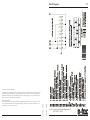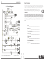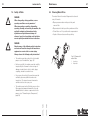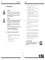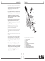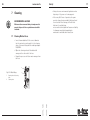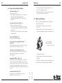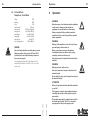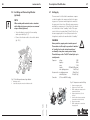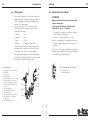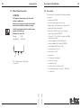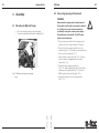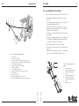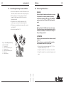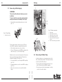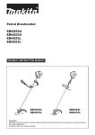
1
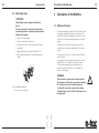
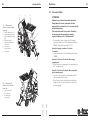
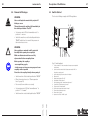
Operating Instructions
387604 – 04/2003
Plastering Machine
mono-mix fu
2
mono-mix fu
Circuit Diagram
© 2002 m-tec mathis technik gmbh
387604 – 04/03
Technical development:
The manufacturer reserves the right to modify technical data without notification in order to reflect the current
state of technical development. For information regarding the current status, alterations or additions to these
operating instructions, please contact m-tec.
387604 – 04/03
Copyright in these operating instructions is owned by m-tec mathis technik gmbh. These operating instructions
are intended for use by installation, operating and maintenance personnel. They contain technical regulations
and drawings which may not be copied, distributed, used for advertising purposes, or communicated to third
parties either in whole or in part without authorisation.
Fig. 25: Connection and wiring diagram for S6
(391304/001 - 04/03)
71
70
mono-mix fu
Dear Customer,
3
this machine represents the most up-to-date technology and complies fully
with general standards and EC guidelines. This is indicated by the CE symbol
and the enclosed Declaration of Conformity in the pocket on the machine.
11 Circuit Diagram
Before starting the machine for the first time, please remove
the Declaration of Conformity from the pocket and keep it in
a safe place.
Before commissioning the machine, please complete the form below. This is
the easiest way to familiarize yourself with the most important machine data,
and to have them ready at all times without having to refer to the rating plate
on the machine. If you wish to contact us at any time, please have the information on this page ready. The data you require can be found on the machine
plate.
Type ________________________________________
Machine no. _________________________________
Year of manufacture _________________________
Power supply _______________________________
Rated current
(total) _______________________________________
Date of commissioning ______________________
(391304/001 - 04/03)
387604 – 04/03
Fig. 24: Circuit diagram mono-mix fu
387604 – 04/03
Application _________________________________
Fig. 23: Spraying units
605160 Spraying unit M25, 200 mm (7.87") long, straight,
with bypass
M25
200
100
V35 (V25)
545155 Spraying unit V35, 100 mm (3.94") long, straight,
with stop valve
545156 Spraying unit V25, 100 mm (3.94") long, straight,
with stop valve
605168 Spraying unit V35, 200 mm (7.87") long, bent
605169 Spraying unit V35, 400 mm (15.75") long, bent
605170 Spraying unit V35, 600 mm (23.62") long, bent
Operation ................................................................................................................................... 47
6.1 Filling the Machine ............................................................................................................ 48
6.2 Adjusting Material Consistency ........................................................................................ 48
6.3 Mixing and Pumping .......................................................................................................... 49
6.4 Spraying with the Spraying Unit ....................................................................................... 50
6.5 Spraying with the Fine-Plaster Spraying Unit ................................................................... 51
6.6 Removal of Blockages ....................................................................................................... 52
6.7 Intervals in Work ................................................................................................................ 53
6.8 Winter Operation ............................................................................................................... 54
6.9 Finishing Work ................................................................................................................... 55
605165 Spraying unit V35, 200 mm (7.87") long, straight
605166 Spraying unit V35, 400 mm (15.75") long, straight
605167 Spraying unit V35, 600 mm (23.62") long, straight
6
V35
Start-up ...................................................................................................................................... 35
5.1 Connecting to Water Supply ............................................................................................. 36
5.2 Connecting the Water Pump ............................................................................................. 37
5.3 Water Supply from Drum .................................................................................................. 38
5.4 Connecting Mortar Hoses ................................................................................................. 39
5.5 Connecting Spraying Unit (optional) ................................................................................. 41
5.6 Connecting Fine-Plaster Spraying Unit (optional) ............................................................ 42
5.7 Mains Power Connection .................................................................................................. 44
5.8 Rotation Direction of Motor .............................................................................................. 45
5.9 Installing and Connecting Vibrator (optional) ................................................................... 46
200
400
600
5
V35
Assembly .................................................................................................................................... 32
4.1 Mounting the Material Trough .......................................................................................... 32
4.2 Assembling the Screw Pump ............................................................................................ 33
4.3 Assembling Portioning Screw and Motor ........................................................................ 34
69
200
400
600
4
605148 Spraying unit M25, 200 mm (7.87") long, bent
605149 Spraying unit M25, 400 mm (15.75") long, bent
605150 Spraying unit M25, 600 mm (23.62") long, bent
Transport / Set-up ..................................................................................................................... 31
3.1 Transporting the Machine ................................................................................................. 31
3.2 Setting the Machine up ..................................................................................................... 31
605145 Spraying unit M25, 200 mm (7.87") long, straight
605146 Spraying unit M25, 400 mm (15.75") long, straight
605147 Spraying unit M25, 600 mm (23.62") long, straight
3
200
400
600
Description of the Machine ...................................................................................................... 19
2.1 Method of Function ........................................................................................................... 19
2.2 Switch Cabinet .................................................................................................................. 21
2.3 Operating Elements on Switch Cabinet ........................................................................... 22
2.4 Connections on Switch Cabinet ....................................................................................... 24
2.5 General Technical Data ...................................................................................................... 25
2.6 Technical Data Pump Area / Gear Motor .......................................................................... 26
2.7 Air Supply ........................................................................................................................... 27
2.8 Water Supply ..................................................................................................................... 28
2.9 Accessories ....................................................................................................................... 29
2.10 Symbols on the Machine .................................................................................................. 30
M25
2
200
400
600
Safety ........................................................................................................................................... 6
1.1 Warning Symbols and Hazard Categories .......................................................................... 6
1.2 General Safety Instructions ................................................................................................. 8
1.3 Intended Use ..................................................................................................................... 10
1.4 Target Group ...................................................................................................................... 10
1.5 Qualified Personnel ........................................................................................................... 11
1.6 Safety at Work ................................................................................................................... 12
1.7 Personal Safety Equipment ............................................................................................... 18
387604 – 04/03
1
Spare Parts / Accessories
M25
mono-mix fu
387604 – 04/03
4
68
mono-mix fu
Contents
10.2 Accessories
The following accessories are available for the monomix fu:
• Various spraying units; these are shown on
page 65
• Order no. 600146 test pressure gauge for
compressor, complete
• Order no. 603048 vibrator, 230 V, complete
• Order no. 601283 pressure-testing device complete
with coupling M25; the pressure-testing device is
coupled to the pump end piece and tests the
delivery pressure of the screw pump
7
Cleaning ..................................................................................................................................... 56
7.1 Cleaning Mortar Hoses ..................................................................................................... 56
7.2 Cleaning the Pump Mixing Pipe ........................................................................................ 57
7.3 Dismantling into Components .......................................................................................... 58
8
Maintenance .............................................................................................................................. 60
8.1 General Care and Maintenance Work ............................................................................... 60
8.2 Cleaning Water Filters ....................................................................................................... 61
8.3 Lubricant Change .............................................................................................................. 62
9
Troubleshooting ........................................................................................................................ 63
9.1 Faults/Errors at Start-up .................................................................................................... 63
9.2 Faults/Errors during Operation .......................................................................................... 64
9.3 Faults in Frequency Inverter .............................................................................................. 66
10 Spare Parts / Accessories ........................................................................................................ 67
10.1 Spare Parts ......................................................................................................................... 67
10.2 Accessories ....................................................................................................................... 68
387604 – 04/03
387604 – 04/03
11 Circuit Diagram ......................................................................................................................... 70
5
6
mono-mix fu
1
Spare Parts / Accessories
10 Spare Parts / Accessories
Safety
WARNING
1.1 Warning Symbols and Hazard Categories
Death or serious injury or damage to the machine
itself or to other property could occur when
- using spare parts and accessories not supplied by
m-tec mathis technik gmbh or when
- modifying the machine.
Use only spare parts and accessories supplied by
m-tec mathis technik gmbh.
The manufacturer will assume no liability for any
accidents or damage caused by the use of spare
parts and accessories of other types or unauthorized modification or conversion of the machine.
In these Operating Instructions and according to the
standards defined in ANSI Z535.1-5, the following
hazard categories are used to draw attention to
possible dangers which may occur when using the
mono-mix fu Plastering Machine.
Depending on the seriousness of the hazard, the
messages are divided into five hazard categories.
The signal words communicate the level of hazard
seriousness.
DANGER
!
Please send orders for spare parts to
m-tec mathis technik gmbh, Sales Dept.:
Tel. Nr.:
+49 / 7631 / 709-112 or -216
Telefax:
+49 / 7631 / 709-116
indicates an imminently hazardous situation
which, if not avoided, will result in death or
serious injury.
WARNING
!
10.1 Spare Parts
indicates a potentially hazardous situation which,
if not avoided, could result in death or serious
injury.
•
•
•
•
CAUTION
indicates a potentially hazardous situation which,
if not avoided, may result in minor or moderate
injuries.
•
•
•
•
CAUTION
387604 – 04/03
is used without safety alert symbol to indicate a
potentially hazardous situation which, if not
avoided, may result in property damage.
387604 – 04/03
!
67
Spur-wheel back-geared motor (3.0 kW)
Motor coupling, motor rocker
Safety grid
Pump mixing pipe with material trough
mixer shaft, pump flange
Screw pump, rotor, stator
Pump end piece M35
Cleaning device
Switch cabinet 230 V complete
For further spare parts, refer to our spare-parts
catalogue.
!
66
mono-mix fu
Safety
NOTICE / ATTENTION
9.3 Faults in Frequency Inverter
is used without safety alert symbol to indicate a
potential situation which, if not avoided, may
result in an undesirable event or state.
When faults occur in the frequency inverter, the red alarm light on the
switch cabinet lights up. The machine does not start.
Error
Overload protection triggers (consistency
too thick; to many hoses laid out)
Machine switched on and off with main
switch
Frequency inverter overheated, cooler defect
Remedy
Set consistency, fewer hoses
The signal word is accompanied by a pictogram
which can be of different shape to emphasize the
kind of hazard. It is followed by a statement of the
hazard, the probable consequence of involvement
with the hazard and how the hazard can be avoided.
Set double push button “On/Off” to “Off”
main switch to “0”; then leave machine
switched off for at least 1 minute
To avoid this type of fault, switch the
machine on and off remotely or at double
push button “On/Off”, never at the main
switch
Replace or repair cooler on frequency inverter
Further symbols and signal words used in these
Operating Instructions:
FI CIRCUIT BREAKER
This symbol points out that only FI circuit breakers
with the symbol shown opposite should be used.
With alarm signals of any kind, the machine must be switched off at the
double push button “On/Off” and then the main switch set to “0”.
After correcting the fault, wait for at least 1 minute before the frequency
inverter is ready for operation before switching the machine on again.
ENVIRONMENTAL HAZARD
This symbol points out that environmental
regulations must be observed.
INFORMATION / NOTE
This symbol draws your attention to important or
additional information relevant to the machine or
documentation.
EYE PROTECTION
387604 – 04/03
387604 – 04/03
This symbol points out that safety goggles must be
worn.
The frame of the goggles must comply with the
standard DIN 58211 (part 2) and the safety lenses
with DIN 4647 (sheet 5).
7
8
mono-mix fu
Troubleshooting
1.2 General Safety Instructions
DANGER
Follow these safety instructions carefully. Failure
to do so may result in increase of risk of accident
or injury. These safety instructions must always be
adhered to when transporting, assembling,
operating, maintaining or disassembling this
machine. These safety instructions apply to the
instructions throughout this manual, and must be
applied to all facets of the machine’s use,
including, but not limited to, transport, assembly,
operation, maintenance or disassembly.
The mono-mix fu Plastering Machine has a stateof-the-art design, it is reliable in operation and it
has left the factory in perfect condition. Nevertheless, it can pose a danger if it has been installed
improperly or contrary to directions (see chapter
3), or it is operated by untrained personnel.
In order to protect the machine from damage and
enable personnel to operate it properly and safely
every operator must observe the following
instructions before starting up the machine:
•
Read and understand the Operation and Service Manual and familiarize with how the machine
is operated. The chapter on “Safety” is particularly
important.
•
Observe the pertinent accident prevention
regulations as well as other generally recognized
rules and regulations pertaining to industrial safety
and medical care.
387604 – 04/03
•
Ensure that any difficulties are resolved
before starting up the machine (see
manufacturer’s address on the back of the cover).
387604 – 04/03
!
65
Error
Motor-protection switch
on compressor triggers
Hose-pressure gauge
indicates high pressure
Cause
Intake filter clogged,
compressor heats up
Mortar hose kinked or
blocked
Material too thick
Hose too long
Air nozzle clogged
Machine switches off
during spraying
Machine cannot be
switched on remotely
Safety valve on compressor
does not close
Safety valve on compressor
set too low
Air-pressure monitor set
too high
Compressor generates too
little air
Remedy
Clean intake filter or replace it
Lay mortar hose as straight as
possible; remove blockage
Set consistency thinner
Shorten mortar hose
Remove air nozzle on spray unit
and clean
Release safety valve
Set valve to 3.2 - 3.5 bar
(46.4 - 50.75 psi)
Set air-pressure monitor to 1.8 bar
(26.1 psi) switch-off pressure
Check air filter, check membrane and
valve plate and replace if necessary.
64
mono-mix fu
Safety
The Operation and Service Manual must always be
kept in the specially designed pocket on the
machine, so that it will be accessible to all
machine operators at all times. All personnel
operating or servicing the machine must be told
where to find this Manual.
9.2 Faults/Errors during Operation
Mortar too thick
Frequency-inverter fault
Too little water
Mortar too thin
Uneven mortar consistency
Impossible to set correct
water quantity
Machine switches off
Motor-protection switch
triggers (Press switch
in before repairing fault)
Too much water
Water filter in press. reducer
or inlet clogged
Material accumulation
on mixing shaft or pipe
Mixing shaft worn
Pump end piece dirty
Rotor and stator worn
Filter in pressure
reducer blocked
Pressure reducer set to
low
Water inlet on mixing
pipe blocked
Water-inlet filter clogged
Water supply fault
Material too thick
Screw pump too tight
Screw pump stuck
Pump end piece clogged
Remedy
Using selector switch “forward/
reverse”, allow the pump to run back
and forward for a short time
(see page 66)
Check water infeed,
Open fine-control valve further
Close fine-control valve further
Clean water filters
Modifications of the machine are not permitted. All
replacement parts, accessories and lubricants
must be furnished by m-tec mathis technik gmbh.
The use of unauthorized parts, accessories or
lubricants may result in death or serious injury,
may cause damage to the machine and will nullify
all liability on the part of the manufacturer for
resultant damage.
Clean dirty parts
Wear proper personal protective equipment,
including, but not limited to, eye and hearing
protection at all times while operating machinery.
Keep hands, feet, hair and clothing away from all
moving parts of the motor to prevent risk of
serious injury. Avoid wearing loose-fitting clothing
or jewelry when near the motor, and secure long
hair in order to keep it away from moving parts.
Replace mixing shaft
Clean pump end piece
Replace rotor and stator
Remove and clean filter
Set pressure reducer to
2 bars (29 psi) switch-off pressure
Remove water hose with GEKA
coupling and clean inlet
pipe
Remove and clean filter
Check water supply and
restore
Set material consistency
thinner
Loosen screw pump slightly
Allow pump to run back and forward
once or twice, replace if necessary;
Clean pump end piece
This machine must be operated in compliance
with all applicable federal, state and local laws,
regulations, and ordinances at all times. This
includes, but is not limited to, the requirements of
TITLE 29 of the CODE OF FEDERAL REGULATIONS,
PART 1926 (29 CFR 1926). Failure to operate this
machinery in compliance with all applicable laws,
regulations, and ordinances may result in death or
serious injury.
387604 – 04/03
Cause
Screw pump stuck
387604 – 04/03
Error
Motor does not start
9
10
mono-mix fu
Troubleshooting
The proper use of this machinery requires that the
operator be in full control of the machinery at all
times. None of this equipment must be used by an
operator that is under the influence of alcohol or
drugs, including prescription drugs that may
impair an operator’s ability to safely operate this
equipment. Failure to adhere to this requirement
may result in death or serious injury.
9
Troubleshooting
WARNING
To prevent death or serious injury, damage to the
machine itself or to other property, always comply
with the safety notes in each section of these
Operating Instructions!
This table is not intended to replace the detailed
instructions in the appropriate sections.
1.3 Intended Use
The correct use of the mono-mix fu consists in mixing
and pumping of previously-mixed dry material with a
maximum grain size of 3 mm (0.118") such as mortar
or ready-mixed lime-gypsum plasters.
!
9.1 Faults/Errors at Start-up
Error
Machine cannot be
switched on
DANGER
Use of the machine for any other purpose than that
described above, may result in bodily or even fatal
injury, damage to the machine itself or to other
property.
It may also impair the efficient functioning of the
machine.
Use of the machine for any other purpose than that
described above is prohibited!
Cause
no mains voltage
no water pressure
Water-inlet pressure
too low
1.4 Target Group
This document is intended for personnel carrying out
start–up, operation and maintenance of the machine.
Such personnel must be qualified according to
specifications stated in chapter 1.5.
Water-pressure monitor
wrongly set
387604 – 04/03
The 4-pole flange
socket in cabinet
is not assigned
387604 – 04/03
!
63
Remedy
Check power connection and plug
in if necessary
Check fuses in site power distributor
Check water infeed hoses/pipes
Check water-infeed filter
Solenoid valve on water fitting
defective and does not open:
replace
Increase pressure of water feed
(min. 2 bar (29 psi)); if necessary use
pressure-increasing pump
Check water press. monitor:
Switch-on pressure 2.5 bar (36.3 psi);
Switch-off pressure 2.0 bar (29 psi)
Use pressure-increasing pump
if necessary
Plug control cable for air-pressure
monitor of spraying unit or
fine-plaster spraying unit into
4-pole flange socket
62
mono-mix fu
Safety
8.3 Lubricant Change
11
1.5 Qualified Personnel
ATTENTION
DANGER
Gear and motor may overheat if overfilled with
lubricant.
Always respect filling levels and do not mix different types of oil and grease.
Non-compliance with lubricating instructions will
invalidate the guarantee.
Start–up, operation and maintenance of the
machine carried out by unqualified personnel, may
result in bodily or even fatal injury, damage to the
machine itself or to other property.
Start–up, operation and maintenance of the
machine may only be carried out by qualified
personnel.
ENVIRONMENTAL HAZARD
It is the duty of the operator to ensure that
operating staff has read and understood the
operating manuel, in particular the chapter
"Safety", and that it is sufficiently qualified for
operating the machine.
Always observe environmental regulations when
disposing of oil, grease or cleaning agents.
The gear motors are ready for operation on delivery
and are maintenance-free up to 8000 hours of
operation.
Qualified persons are those who, through training or
experience, have sufficient knowledge in the field of
mortar-feeding and mortar-spraying machines and
who are sufficiently familiar with legislation regarding
safety, accident prevention, guidelines and general
technical procedures to allow them to assess the
safe condition of such machines.
ATTENTION
After every 8000 hours of operation, the gears must
be cleaned using a suitable flushing oil and then
checked.
After cleaning, refill with fresh lubricant of a
suitable type.
As grease charge for the motor, we recommend
fluid grease of type Esso S420, quantity 420 cc.
387604 – 04/03
387604 – 04/03
If the recommended type of grease is not available,
the following types may also be used:
Aral
FDP 00
BP
Energrease HTO
Esso
Fibrax EP-370
Mobil
Mobilplex 44
Shell
Special Gear Grease H
!
12
mono-mix fu
Maintenance
8.2 Cleaning Water Filters
1.6 Safety at Work
The water filters in the water fitting must be cleaned
every 4–6 weeks.
DANGER
!
61
When disregarding safety regulations, secure
operating conditions are not guaranteed.
When transporting, assembling, dismantling,
operating, cleaning, and servicing the machine, the
applicable national and international safety
regulations and legislation must always be
observed, even if such regulations and legislation
are not explicitly mentioned in these instructions.
• Open pressure reducer with special key and
remove filter
• Open water inlet with special key and remove filter
• Clean filters well – if possible with compressed air
• Replace filters and secure with special key
DANGER
Nonobservance of the following safety instructions
and notes will result in damage to the machine or
equipment or even in death or serious injury
Always observe the following safety instructions!
Fig. 22: Removal of
water filters
• The machine must be used only for its intended
purpose (see "Intended Use", page 10)!
1
• Before every shift, the machine must be carefully
inspected by the foreman for obvious signs of
damage, in particular to electric cables, plugs,
couplings, mortar hose and air hose.
• If necessary, the safety of the machines must be
verified by a person qualified to make such
inspections. The inspection must however be
carried out at least once per year.
387604 – 04/03
• The machine must not be lifted by crane or other
lifting gear, but transported manually. It can be
dismantled into its various components for this
purpose (see “Dismantling into Components”,
page 58).
387604 – 04/03
!
2
1
2
Special key
Water filter
60
mono-mix fu
8
Safety
Before dismantling the machine, the following
operations must be carried out:
- the machine must be run until it is empty (see
“Finishing work”, page 55);
- the mortar hoses must be de-pressurized
according to instructions and uncoupled (see
“Finishing work”, page 55);
- the machine must be switched off at the push
button “On/Off” and the main switch set to “0”;
- all electric cables, water and air hoses must be
removed.
Maintenance
WARNING
Danger of electrocution as certain components
remain live even when the machine is switched off.
Before working on electrical components, always
pull out the power plug.
WARNING
• The machine must be positioned in an area where
no objects can fall onto it. If this is not possible,
the machine and the area around it must be
protected by a roof.
Nonobservance of the maintenance and lubrication
instructions could result in damage to the machine
or equipment or even in death or serious injury.
Always observe the maintenance and lubrication
instructions!
m-tec mathis technik gmbh will assume no liability
for damage caused by disregarding the
maintenance and lubrication instructions.
• The machine must be positioned firmly on a level
surface. It must be secured to prevent it from
tilting or moving.
• The work area at the switch cabinet and the area
around the pump unit must be easily accessible.
8.1 General Care and Maintenance Work
• The machine must be connected to a regulation
site distributor box with FI automatic circuit
breaker. Before use, the function of the FI circuit
breaker must be tested while the machine is
running, as the frequency inverter may cause the
circuit breaker to malfunction.
• Before every shift, check the machine for signs of
obvious damage, in particular to hose and cable
connections
• Clean material residues off mixing pipe, material
trough and mixing shaft
• Clean compressor air filter
FI CIRCUIT BREAKER
387604 – 04/03
Only FI circuit breakers with the symbol shown
opposite should be used. Required fuse:
20 A (min.)
387604 – 04/03
!
13
mono-mix fu
Cleaning
59
• Ensure that the safety grid is mounted securely on
the material trough. Do not put your hands into the
material trough. Do not place objects in the
material trough.
4
• We recommend installing a hose-pressure gauge.
This allows the pressure in the mortar hoses to be
monitored at all times, increases the safety of the
operating personnel and ensures economical
operation. A hose-pressure gauge is not supplied
with the mono-mix fu.
3
2
5
6
• For safety reasons, use only mortar hoses with a
permitted operating overpressure of 40 bars
(580.2 psi) and a bursting pressure of at least 120
bars (1740.5 psi).
7
8
• During operation, the pressure of 20 bars
(290.1 psi) must not be exceeded (monitor
pressure on hose-pressure gauge).
1
• If blockages occur, the machine must be switched
off immediately at the double push button “On/
Off”.
9
• Always de-pressurize mortar hoses before uncoupling them.
Check the pressure on the hose-pressure gauge
before opening them. Cover the coupling with a
tarpaulin. Wear regulation goggles and do not face
the coupling directly, as material may be ejected
forcefully.
Fig. 21: Dismantling into components
1
2
3
4
5
6
7
8
9
387604 – 04/03
• If the machine is switched off by means of the
spraying unit (close air valve) or the fine-plaster
spraying unit (close stop valve), it is still on standby
and can be switched on by triggering the spraying
unit or the fine-plaster spraying unit. This is
signalized by a white lamp lighting up on the
double push button “On/Off”.
387604 – 04/03
14
Eccentric lock of motor
Mixing shaft
Motor
Motor plug
Bolt on motor rocker, secured with cotter pin
Interior water feed
Clamping wedge, both sides
Cotter pin on clamping wedge, both sides
Screw pump consisting of rotor and stator
58
mono-mix fu
Safety
INFORMATION
• Switch machine off at double push button “On/Off”
and set main switch to “0”.
• Rinse the pump-end piece with spray nozzle.
For the sake of simplicity, the following sentence is
used in these instructions to refer to the abovementioned safety note:
If the machine is switched to “standby” it is still
ready for operation and can be started remotely at
any time. Indication: the white lamp on the “On/
Off” button lights up.
7.3 Dismantling into Components
WARNING
To prevent electrical shock or projection of hose
couplings or mortar the following operations must
be carried out before dismantling the machine:
- it must be run until empty (see “Finishing work”,
p. 55);
- the mortar hoses must be fully de-pressurized
according to instruction and then uncoupled
(see “Finishing work”, p. 55);
- the machine must be switched off at double
push button “On/Off” and the main switch set
to “0”;
- all electric cables, water and air hoses must be
removed.
• Never point the spraying unit or the fine-plaster
spraying unit at persons!
• The Troubleshooting Table is not intended to
replace the detailed instructions in the appropriate
sections of these Operating Instructions. Always
comply with the safety notes in each section!
• Before working on electrical components, always
pull out the power plug, as certain components
remain live even when the machine is switched off.
• Use only spare parts and accessories supplied by
m-tec mathis technik gmbh. If spare parts and
accessories of other types are used, m-tec mathis
technik gmbh will assume no liability for damage
caused.
Remove pump end piece with screw pump:
• Remove securing pin of clamping wedges
• Release clamping wedges
• Remove pump end piece and screw pump
• Modifications to the machine are prohibited. The
manufacturer will assume no liability for damage
caused by unauthorized modification or conversion
of the machine.
Remove motor and motor rocker from mixing pipe:
• Release eccentric lock
• Remove cotter pin on securing bolt and pull bolt
out
• Remove motor and rocker
• Pull mixing shaft out of the mixing pipe
• To avoid unnecessary loading of the machine and
premature wear to the spiral pump, do not lay out
more mortar hoses than are actually required.
387604 – 04/03
Remove material trough with mixing part:
• Release wedge
• Pull the material trough forward and out
387604 – 04/03
!
15
mono-mix fu
Cleaning
• For operation, the direction of rotation of the motor
must be set to “1=forward”.
7.2 Cleaning the Pump Mixing Pipe
• Pull out the motor plug (fig. 21, 4)
• The machine must only be switched on and off at
the double push button “On/Off”, or using the
spraying unit or fine-plaster spraying unit. Never
use the main switch. If the machine is switched off
repeatedly at the main switch, the frequency
converter may malfunction.
WARNING
Moving parts can crush and cut.
Before working on the pump, pull out the motor
plug.
• Release the eccentric lock (fig. 21, 1) of the motor
• Fold the motor (fig. 21, 3) down
• Pull the mixer shaft (fig. 21, 2) out of the mixing
pipe and material trough
• Clean the mixer shaft thoroughly
• Insert cleaning device into the mixing pipe
• Fold motor up again and secure with eccentric lock
• Re-insert motor plug and switch machine on at
double push button “On/Off”
• Allow the machine to run until the cleaning device
has moved to the bottom
• Switch machine off at double push button “On/Off”
and pull out motor plug
• Do not use the material until the adequate consistency has been reached. Catch any material emerging beforehand in a bucket and dispose of it
correctly.
• During intervals in work, remember the time required for the material to set. The material sets
more rapidly at high temperatures. If the interval in
work is longer than 30 minutes, the machine and
the mortar hoses must be emptied beforehand
(see “Finishing work”).
• Below freezing temperature, water fittings may be
damaged if allowed to freeze.
WARNING
• If the machine is being run until empty, do not use
the watery material in the machine.
Danger of electrocution as certain components
remain live even when the machine is switched off.
Before working on electrical components, pull out
the motor plug.
• Mortar residues removed during cleaning must be
properly disposed of in a regulation waste-rubble
container.
• Release the eccentric lock of the motor and fold it
down
• Remove the cleaning device
• Re-install the clean mixing shaft
• Fold motor up again and secure with eccentric lock
• Re-insert the motor plug and switch machine on at
double push button “On/Off”
• Allow the machine to run briefly to ensure that the
screw pump is properly flushed
387604 – 04/03
• Overfilling the gear unit and motor with lubricant
may cause overheating. Do not mix different types
of oil and grease.
387604 – 04/03
16
57
56
mono-mix fu
7
Safety
• Always observe environmental regulations when
disposing of oil, grease or cleaning agents.
Cleaning
• After every 8000 hours of operation, the gears
must be cleaned using a suitable flushing oil and
then checked. After cleaning, refill with fresh
lubricant of a suitable type.
m-tec mathis technik gmbh will assume no liability
for damage caused by disregarding the
maintenance and lubrication instructions.
ENVIRONMENTAL HAZARD
Mortar residues removed during cleaning must be
properly disposed of in a regulation waste-rubble
container.
7.1 Cleaning Mortar Hoses
• Insert a foam-rubber ball of the correct diameter
into the mortar hose and couple it to the cleaning
valve of the water fitting with the reducing adapter
M35/GEKA.
• Open the cleaning valve until the rubber ball
emerges at the other end of the hose
• Repeat the process until clean water emerges from
the hose.
2
Fig. 20: Water fitting
387604 – 04/03
2
1
Opening lever of cleaning
valve
Cleaning valve
387604 – 04/03
1
17
18
mono-mix fu
Operation
1.7 Personal Safety Equipment
6.9 Finishing Work
• Allow the machine to run until the mortar trough and
hoses are empty
WARNING
Nonobservance of the following safety instructions
could result in serious injury.
ATTENTION
Always observe the following safety instructions!
To avoid overload of the machine do not use
mortar which is too thin.
• The proprietor/operator of the machine must
supply personal noise-protection equipment for
personnel using the machine if the noise level at
the place of work exceeds 85 dB (A).
• Switch machine off at double push button “On/Off”
• Set reverse switch “Motor forwards/reverse” to
position “2 = reverse”
• Switch the machine on at the double push button
“On/Off” and allow it to run until the pressure in
the mortar hoses is zero
• If the noise level at the place of work exceeds
90 dB (A), the use of this equipment by personnel
is compulsory.
• Always wear safety goggles when removing
blockages and during spraying work.
WARNING
Hose couplings or material could be projected
forcefully when opening hose couplings.
Make sure that mortar and hoses are fully
depressurized before uncoupling them.
Before opening the couplings:
- wear regulation goggles,
- check pressure on hose-pressure gauge and cover
couplings with a tarpaulin.
Do not face the coupling directly when opening it.
• The frame of the goggles must comply with the
standard DIN 58211 (part 2) and the safety lenses
with DIN 4647 (sheet 5).
• During spraying work, always wear a safety helmet
and safety shoes or boots.
387604 – 04/03
• Switch machine off at double push button “On/Off”
and switch main switch to “0”
• Switch compressor off if necessary
• Clean the machine (see page 56).
387604 – 04/03
!
55
!
54
mono-mix fu
Description of the Machine
6.8 Winter Operation
2
19
Description of the Machine
ATTENTION
Water fittings may be damaged if allowed to
freeze.
For longer intervals in work, in particular below
freezing temperature, completely empty the water
fittings after cleaning.
2.1 Method of Function
The mixer and pump components of the mono-mix fu
are both powered by the same electric motor. The
material is mixed to the adequate consistency in the
mixer section and then pumped out by an eccentric
pump.
The machine is fitted with a frequency converter
which permits continuous adjustment of the motor
speed.
• Switch off water supply
• Remove and empty feeder hose
• Uncouple water hose between water fitting and
mixer pipe
• Open draining valves of water fitting (fig. 19)
• Close draining valve before starting machine up
again
The mono-mix fu can be controlled directly from the
switch cabinet.
If a spraying unit is being used, the machine can be
switched on or to “standby” using the air valve.
If a fine-plaster spraying unit is being used, the
machine can be switched on or to “standby” by
means of the trigger.
WARNING
Never point the spraying unit at another person!
The machine is still ready for operation if switched
to "standby" and can be started remotely and
accidentally at any time causing serious injury.
The white lamp on the “On/Off” button lights up in
standby mode.
1
Fig. 19: Drainage of valves
387604 – 04/03
Draining valves on water fitting
387604 – 04/03
1
!
20
mono-mix fu
Operation
6.7 Intervals in Work
1
2
3
ATTENTION
Material may set inside the machine and hoses.
During intervals in work, remember the time
required for the material to set. It sets more rapidly
at high temperatures.
If the interval in work is longer than 30 minutes,
the machine and the mortar hoses must be
emptied beforehand (see “Finishing work”).
Fig. 1: Mono-mix fu,
general view from righthand side
1
2
3
4
5
6
7
8
Switch cabinet (see p. 21)
Motor or mixer and pump
Material trough with safety
grid
Pump mixing pipe
Machine interior water
connection
Spiral pump
Pump end piece
Compressor
4
5
• For intervals in work of more than 10 minutes,
switch the machine off at the double push button
“On/Off” and switch main switch to “0”!
6
Intervals in pump operation of less than
10 minutes:
• Switch the machine off at the double push button
“On/Off”
8
Intervals of less than 10 minutes when using
spraying unit:
• Close air valve on spraying unit; the machine goes
into “standby mode”
7
Intervals of less than 10 minutes when using fineplaster spraying unit:
• First close the stop valve to the beginning of the
red zone marked on the lever
• Close the stop valve entirely when pressure has
dropped to zero in the mortar hoses (check hose
pressure gauge).
Fig. 2: Mono-mix fu,
general view from lefthand side
1
2
387604 – 04/03
2
Water connections
(see page 28)
Air connections
(see page 27)
387604 – 04/03
1
53
52
mono-mix fu
Description of the Machine
2.2 Switch Cabinet
6.6 Removal of Blockages
The electrical fittings comply with VDE regulations.
WARNING
Hoses could explode or material be projected if
blockages occur.
The machine must be switched off immediately at
the double push button “On/Off”.
4 5
6
• Set reverse switch “Motor forwards/reverse” to
position 2 = reverse
• Switch the machine on at the double push button
“On/Off” and allow it to run until the pressure in
the mortar hoses is zero.
3
7
8
2
9
1
WARNING
Hose couplings or material could be projected
forcefully when opening hose couplings.
Make sure that mortar and hoses are fully
depressurized before uncoupling them.
Before opening the couplings:
- wear regulation goggles,
- check pressure on hose-pressure gauge and cover
couplings with a tarpaulin.
Do not face the coupling directly when opening it.
13 12 2 11
10
Fig. 3: Switch cabinet
1
2
3
4
5
6
7
8
9
10
11
12
13
387604 – 04/03
• Switch machine off at double push button “On/Off”
• Clean the mortar hoses (see “Cleaning mortar
hoses”, page 56)
• Re-connect the mortar hoses securely
• Set reversing switch “Motor forward/reverse” to
position “1 = forward”
• Switch machine on at double push button “On/Off”
387604 – 04/03
!
21
Safety socket 250 V for connection of compressor or optional
water pump
4-pole socket for control cable of pressure monitor “Air” or
fine-plaster spraying unit
4-pole cube plug for connection of a vibrator
Main switch
Double push button “On-Off”
Push button “Water infeed”
Pole-changing switch “motor forward/reverse”
Signal lamp “Fault frequency inverter”
4-stage switch “motor speed”
Connection for pressure monitor “water”
Connection for solenoid valve
Power cable “motor”
Input socket 250 V, L6-20A 3-pole
22
mono-mix fu
Operation
2.3 Operating Elements on Switch Cabinet
6.5 Spraying with the Fine-Plaster Spraying
Unit
Main Switch (Fig. 3, 4)
In position “0” the machine is disconnected; in
position “1” it is ready for operation.
WARNING
Never point the spraying unit at another person!
The machine is still ready for operation if switched
to "standby" and can be started remotely and
accidentally at any time causing serious injury.
The white lamp on the double “On/Off” button
lights up in standby mode.
ATTENTION
Never use the main switch to switch the machine
on and off.
The frequency converter may malfunction when
switching the machine off repeatedly using the
main switch.
The machine must only be switched on and off at
the double push button “On/Off”, or using the
spraying unit or fine-plaster spraying unit.
• Ensure that the compressor is switched on: set
selector switch to “1” (fig. 17, 1)
• Ensure that the control cable of the fine-plaster
spraying unit is plugged in to the switch cabinet
(fig. 18, 1)
• Ensure that the air valve on the fine-plaster
spraying unit is closed
• Set main switch to “1”
• Switch machine on at double push button “On/Off”
Double Push Button “On/Off” (Fig. 3, 5)
The machine can be switched on and off with the
double push button “On/Off”. Indication: when the
machine is switched on and ready for use, the white
signal lamp on the double push button “On/Off”
lights up.
The machine is now ready for operation, i.e. in standby mode. However, it only starts when the stop valve
on the fine-plaster spraying unit is opened.
When the stop valve on the fine-plaster spraying unit
is closed again, the machine switches back to standby mode.
WARNING
387604 – 04/03
Never point the spraying unit at another person!
The machine is still on standby when switched off
by means of the spraying unit (air valve) or the
fine-plaster spraying unit (stop valve).
It can be switched on accidentally by triggering
the spraying unit or the fine-plaster spraying unit.
The white lamp on the “On/Off” button lights up in
standby mode.
387604 – 04/03
!
51
!
50
mono-mix fu
Description of the Machine
Button “Water Infeed” (Fig. 3, 6)
The button “Water infeed” is needed to set the
correct quantity of water at start-up. As long as it is
kept pressed, the solenoid valve also opens when the
machine is not switched on with the double push
button “On/Off”.
6.4 Spraying with the Spraying Unit
WARNING
!
Never point the spraying unit at another person!
The machine is still ready for operation if switched
to "standby" and can be started remotely and
accidentally at any time causing serious injury.
The white lamp on the double “On/Off” button
lights up in standby mode.
Reversing Switch “Motor Forward/Reverse”
(Fig. 3, 7)
For normal operation the reversing switch is at
“forward”. The position “reverse” is required for
reducing the pressure in the mortar hoses (for
removing blockages or when finishing work).
• Ensure that the compressor is switched on: set
selector switch to “1” (fig. 17, 1)
• Ensure that the control cable of the air-pressure
monitor is plugged in to the switch cabinet
(fig. 18, 1)
• Ensure that the air valve on the spraying unit is
closed
• Set main switch to “1”
• Switch machine on at double push button “On/Off”
Fault-Signal Lamp ”Frequency Inverter” (Fig. 3, 8)
This red lamp lights up to indicate a fault in the
frequency inverter (to correct fault, see section on
troubleshooting).
4-Stage Switch “Motor Speed” (Fig. 3, 9)
Using the 4-stage switch “Motor speed”, the machine
power can be selected in 25% steps up to maximum.
The machine is now ready for operation, i.e. in standby mode. However, it only starts when the air valve
on the spraying unit is opened.
When the air valve is closed again, the machine
switches back to standby mode.
Fig. 18: Connecting the airpressure monitor of fine-plaster
spraying unit.
1
387604 – 04/03
387604 – 04/03
1
Connection socket for control cable
of air-pressure monitor
23
24
mono-mix fu
Operation
• If necessary, adjust the flow quantity (fig. 16, 2)
with the fine-adjustment valve.
• When the desired consistency has been reached,
release the button “water infeed”.
2.4 Connections on Switch Cabinet
Safety Sockets (Fig. 3, 1)
Supply connection for:
• the compressor provided (230 V), for use with a
spraying or fine-plaster spraying unit or
• an optional water pump (230 V) for low mains
pressures.
6.3 Mixing and Pumping
When the machine is not being used for spraying,
observe the following:
• Ensure that the compressor is switched off
(fig. 17, 1)
• Ensure that the control cable of the air-pressure
monitor is plugged into the switch cabinet (fig. 18)
Connection Socket 4-pole (Fig. 3, 2)
The 4-pole connection socket is for:
• connection of control cable of pressure monitor
“air” when the pump is in operation or a spraying
unit is in use;
• connection of control cable for use with fine-plaster spraying unit.
4-pole Cube Plug (Fig. 3, 3)
Connection for optional vibrator.
1
Connection for Pressure Monitor “Water”
(Fig. 3, 10)
The water-pressure monitor controls the inlet water
pressure; it must not be disconnected.
0
1
Fig. 17: Switching
compressor on/off
1
Connection “Solenoid Valve” (Fig. 3, 11)
The solenoid valve opens and closes the internal
water feed in the machine; it must not be
disconnected.
Compressor "On/Off"-switch
• Switch main switch to “1”
• Switch machine on at the double push button
“On/Off”
Supply Cable “Motor” (Fig. 3, 12)
The cable for the motor is plugged in on the motor
side. For safety reasons, the plug is secured to the
frame by a short chain. The chain is too short to allow
the motor to be folded down. If the motor is to be
folded down, the plug must first be removed from the
motor.
387604 – 04/03
The machine now mixes and pumps material until it is
switched off at the double push button “On/Off”.
387604 – 04/03
Infeed Socket L6-20 (Fig. 3, 13)
The machine is connected to the site power
distributor via the infeed socket.
49
48
mono-mix fu
Description of the Machine
2.5 General Technical Data
6.1 Filling the Machine
• Fill the material trough with bagged material
through the safety grid
Dimensions
(with mixer motor and eccentric screw pump)
Length
1430 mm (56.3")
Width
670 mm (26.4")
Height
1150 mm (45.3")
Bag-loading height
980 mm (38.6")
Weight
of which:
incl. accessories approx.
160 kg (352.74 lb)
Accessories
15 kg (33.07 lb)
Mixer unit with material trough incl.
eccentric screw pump
75 kg (165.35 lb)
Small compressor
15 kg (33.07 lb)
Frame with wheels and fittings
55 kg (121.25 lb)
Noise level
76 dB(A); noise-pressure level at 1 m (3.281 ft) distance
(free-field measurement during operation)
6.2 Adjusting Material Consistency
ATTENTION
Wrong water quantity will result in improper
consistency of material.
Mind proper water infeed and do not use material
until sufficient consistency has been achieved.
ENVIRONMENTAL HAZARD
Catch any material emerging beforehand in a
bucket and dispose of it correctly.
• Open the external water supply
• Set the main switch (fig. 16, 1) to “1”
• Keep button “water infeed” (fig. 16, 4) pressed and
read the flow quantity on the flow meter (fig. 16, 3)
1
2
Main switch
Fine adjustment valve
Flow meter
Button “Water infeed”
4
3
387604 – 04/03
1
2
3
4
387604 – 04/03
Fig. 16: Adjusting
material consistency
25
26
mono-mix fu
Operation
2.6 Technical Data
Pump Area / Gear Motor
Voltage
Frequency
Power
Nominal speedl
Pump capacity
Pump pressure
Pump distance
Pump height
max. grain size
max. operating pressure
6
230 V
60 Hz
3 kW
260 r.p.m.
20 l/min (5.28 gal./min)
up to 20 bar (290.1 psi)
up to 20 m (65.6 ft)
up to 10 m (32.8 ft)
3 mm (0.118")
20 bar (290.1 psi)
47
Operation
WARNING
Nonobservance of accident-prevention regulations
could result in damage to the machine or
equipment or even in death or serious injury.
Always comply with the accident-prevention
regulations in force and all generally recognized
safety regulations.
WARNING
Damage to the machine or parts of it could cause
personal injury, electrocution etc.
Before every start-up, inspect the machine
carefully for damage to electric cables, plugs,
couplings, mortar and air hoses etc.
Any damage must be repaired before starting the
machine.
DANGER
Hoses will explode when exceeding hose pressure.
During operation, the pressure of 20 bars (290.1
psi) must not be exceeded (monitor pressure on
hose-pressure gauge).
The pumping quantity and height depend on the
material quality and the condition of the rotor and
stator used.
WARNING
Moving parts can crush and cut.
Do not put your hands or place objects into the
material trough.
Ensure that the safety grid is mounted securely on
the material trough.
387604 – 04/03
387604 – 04/03
ATTENTION
Never use the main switch to switch the machine
on and off.
The frequency converter may malfunction when
switching the machine off repeatedly using the
main switch.
The machine must only be switched on and off at
the double push button “On/Off”, or using the
spraying unit or fine-plaster spraying unit.
!
46
mono-mix fu
Description of the Machine
5.9 Installing and Connecting Vibrator
(optional)
2.7 Air Supply
The mono-mix fu is fitted with a membrane compressor which supplies the compressed air for the spraying process. A pressure monitoring device monitors
the pressure in the air hose. When the pressure generated by the compressor is ≥ 2 bar (29 psi), the machine is switched on from “standby” mode. If the pressure in the hose is greater than 2.5 bar (36.3 psi) (e.g.
because spraying unit is closed) the pressure monitoring device switches the machine back to "standby”.
NOTE
When working with materials such as insulants
with a high polystyrene content, we recommend
using a vibrator (optional).
• Screw the vibrator securely to the mounting
surface provided (fig. 15, 1)
• Connect the vibrator cable to the switch cabinet
(fig. 15, 2)
WARNING
Never point the spraying unit at another person!
The machine is still ready for operation if switched
to "standby" and can be started remotely and
accidentally at any time causing serious injury.
The white lamp on the “On/Off” button lights up in
standby mode.
Compressor
voltage
230 V
frequency
60 Hz
power
1.1 kW
capacity
250 l/min (66.05 gal. min)
max. operating pressure
4 bar (58 psi)
Pressure monitor air starting-up pressure
2.0 bar (29 psi)
switch-off pressure
2.5 bar (36.3 psi)
Connections
3/8" -hose with GEKA coupling
1
2
Fig. 15: Installing and connecting vibrator
Mounting surface
4-pole cube plug for connection of vibrator cable
!
Fig. 4: Compressor and air fitting
1
2
3
4
5
387604 – 04/03
6
7
387604 – 04/03
1
2
27
Compressor power cable
Compressor “On/Off” switch
GEKA-coupling on compressor for
compressed-air hose
Compressed-air hose 3/8" x 0.9
with cpl.
Control cable of pressure monitor
(connection on switch cabinet)
Air-pressure monitor
GEKA-coupling for air connection
of spraying unit
28
mono-mix fu
Start-up
2.8 Water Supply
5.8 Rotation Direction of Motor
The water inlet pressure is controlled by a pressuremonitoring device. If the pressure drops below 2 bar
(29 psi), the machine switches off automatically to
prevent it from running dry.
A built in pump (see fig. 10,1) increases water
pressure when mains water pressure is too low.
Pump specifications are:
• Voltage
230 V
• Frequency
60 Hz
• Power
0.3 kW
• Capacity
40 l/min (10.57 gal./min)
A pressure reducer keeps the water inlet pressure
during operation constant at 2 bar (29 psi) to avoid
fluctuations in the consistency of the material.
ATTENTION
Wrong rotation direction of motor prevents water
supply to mixing pipe.
For operation, the direction of rotation of the
motor must be set to “1 = forward”.
• The direction of rotation is set with the reversing
switch “Motor forwards/reverse”.
Position 1 = forward, position 2 = reverse.
Water is only supplied to the mixing pipe in position
“1” (motor forwards). Only then does the solenoid
valve open.
The position “2” (reverse) is required for reducing the
pressure in the mortar hoses for removing blockages
(see page 52 “Removing blockages”).
The required water quantity is adjusted manually by
means of a fine adjustment valve. A flow meter with
float indicates the flow of water per hour.
Fig. 5: Water fitting
12
387604 – 04/03
7
8
9
10
11
1
Water hose 1/2" x 1.25 m complete
Water inlet
Ball valve 1/2"
Water supply tap
Pressure gauge 0 - 10 bar (0 - 145 psi)
Pressure monitor 1 - 16 bar (14.5 232.1 psi); cut-in pressure 2.5 bar
(36.3 psi); cut-off pressure 2.0 bar
(29 psi)
Pressure reducer 1/2"
2 draining valves 1/4" AG / IG
Solenoid valve 24 V
Pressure gauge 0 - 4 bar (0 - 58 psi)
Flow meter 300 - 1100 l/h (79.3 290.6 gal./h)
Fine adjustment valve 1/2"
387604 – 04/03
1
2
3
4
5
6
45
Fig. 14: Rotation direction of motor
1
Reversing switch
“Motor forward/reverse”
44
mono-mix fu
Description of the Machine
5.7 Mains Power Connection
2.9 Accessories
The mono-mix fu is fitted with the following standard
accessories:
ATTENTION
The frequency inverter may cause the circuit
breaker to malfunction.
Before use, the function of the FI circuit breaker
must be tested while the machine is running.
•
•
•
•
•
Only FI circuit breakers with the symbol shown
opposite should be used.
Required fuse: min. 20 A.
Cable and
Cable plug types:
•
SJ14/3
L6-20A, 3-pole
•
•
•
•
•
•
•
•
•
•
•
•
1
Fig. 13: Input socket, L6-20A,3-pole
387604 – 04/03
387604 – 04/03
1 Input socket
1 Water pump TM61E
Eccentric screw pump, type mono-star
Pump end piece with mortar-hose coupling M 35
Spraying unit with coupling M 25
Mortar hose NW 25, 10 m (11 yds.) in length,
compl. with coupling V 25/M 25
1 air hose 1/2", 11 m (12 yds.) in length, with GEKAcoupling on both ends
1 reducing adapter V 35/V 25 turning part
1 reducing adapter for cleaning M 35/GEKA
1 foam-rubber ball Ø 35 mm (1.38")
1 open-end wrench 10 x 13
2 ring wrench 19 x 24
1 turning tool
1 cleaning tool with handle
1 wrench for sieve pot
1 screwdriver, size 7
1 mortar nozzle, hole 12 mm (0.47")
1 hose-pressure gauge 0–100 bar (0 - 1450.4 psi)
1 cleaning tool
29
30
mono-mix fu
Start-up
43
2.10 Symbols on the Machine
1 2
Storage for Operating Vibrator connection
instructions
Water-pressure
connection
3
4 5
Solenoid-valve
gauge
7
bar
Selector switch
Motor rotation
direction
Button water infeed
Water supply tap
Drain fitting in cold
weather
6
Fig. 12: Connecting the fine-plaster spraying unit
Reversing switch
Motor speed
Compressor connection
Warning for moving/
rotating parts
1
2
3
Inlet water fitting
4
5
6
bar
Connection for control cable for fine
plaster-spraying unit
Connection on machine
only to site power-distributor
with FI circuit breaker
387604 – 04/03
Connection water pump
387604 – 04/03
7
Connection for
control cable
Air pressure monitor
Fine-plaster spraying unit
Stop valve on fine-plaster spraying unit
Connection of compressed-air hose with Geka coupling
to the Geka coupling of the fine-plaster spraying unit.
Socket of control cable on fine-plaster spraying unit
Connection socket for control cable on switch cabinet
Connection of compressed-air hose with Geka coupling
at both ends to the Geka coupling of the compressor.
Connection of mortar hose to fine-plaster spraying unit.
42
mono-mix fu
Transport / Set-up
3
5.6 Connecting Fine-Plaster Spraying Unit
(optional)
31
Transport / Set-up
WARNING
3.1 Transporting the Machine
Never point the spraying unit at another person!
The machine is still ready for operation if switched
to "standby" and can be started remotely and
accidentally at any time causing serious injury.
The white lamp on the double “On/Off” button
lights up in standby mode.
WARNING
To avoid damage to the machine and personal
injury, do not lift the machine by crane or other
lifting gear.
The machine must be transported manually.
• Connect the compressor power cable to a safety
socket in the switch cabinet (L15-3-pole)
• Connect the long compressed-air hose (Geka
coupling at both ends) to the Geka coupling of the
fine-plaster spraying unit (fig. 12, 3) and to the
Geka coupling of the compressor (fig. 12, 6)
• Connect the control cable of the fine-plaster
spraying unit (fig. 12, 4) to the switch cabinet
(fig. 12, 5)
• Connect the mortar hose to the fine-plaster
spraying unit (fig. 12, 7)
!
The machine can be dismantled into its various
components for this purpose (see section
“Dismantling into components”, page 58).
3.2 Setting the Machine up
WARNING
387604 – 04/03
Tilting or moving of the machine could cause
malfunction or damage to the machine or personal
injury.
The machine must be positioned steadily on a level
surface.
The machine must be secured and positioned in an
area where no objects can fall onto it from above.
If this is not possible, the machine and the area
around it must be protected by a roof.
The work area at the switch cabinet and the area
around the pump unit must be easily accessible.
387604 – 04/03
!
!
32
mono-mix fu
4
Start-up
41
5.5 Connecting Spraying Unit (optional)
Assembly
WARNING
Never point the spraying unit at another person!
The machine is still ready for operation if switched
to "standby" and can be started remotely and
accidentally at any time causing serious injury.
The white lamp on the double “On/Off” button
lights up in standby mode.
4.1 Mounting the Material Trough
• Place the material trough on the mixing pipe
• Secure the material trough with the wedge (fig. 6)
• Connect the power cable of the compressor to a
safety socket in the switch cabinet (L15-3-pole)
• Connect the short compressed-air host to the
compressor (fig. 11, 5) and the pressure-monitoring
device on the air fitting (fig. 11, 7)
• Ensure that the control cable (fig. 11, 6) of the airpressure monitor is plugged in at the switch
cabinet (fig. 11, 9)
• Couple the long compressed-air hose
(fig. 11, 4 – Geka coupling both sides) to the Geka
coupling of the spraying unit (fig. 11, 3) and the
GEKA coupling of the air fitting (fig. 11, 8)
• Couple the mortar hose to the spraying unit
(fig. 11, 13)
1
Fig. 6: Wedge fastening of mixing pipe
387604 – 04/03
Wedge
387604 – 04/03
1
!
40
mono-mix fu
Assembly
33
4.2 Assembling the Screw Pump
The screw pump consists of a stator with rotor to fit.
2
3
5
4
6
7 8
• Follow the assembly instructions on the stator
(fig. 7, 8)
• Hook a connecting rod (fig. 7, 7) onto one side of
the pump mixing pipe (fig. 7, 1)
• Place stator with rotor in position (= eccentric
pump) on the pump end piece (fig. 7, 9) without
tilting the rotor and stator
• Hook the second connecting rod onto the pump
mixing pipe
• Using the clamping wedges (fig. 7, 2), tighten the
screw pump including the pump end piece and
secure on both sides with cotter pin
9
13
12
11
10
If the eccentric pump is not secure enough:
• Release the counter nuts of the connecting rods
(fig. 7, 6)
• Tighten the tensioning nuts (fig. 7, 5 – both sides)
and re-secure them with the counter nuts
Fig. 11: Connecting spraying unit
Spraying unit
Air valve on spraying unit
Air connection with Geka coupling on spraying unit
Compressed-air hose, with Geka coupling at both ends
Geka coupling on compressor
Control cable of air-pressure monitor
Air-pressure monitor
Geka coupling on air fitting
Socket for control cable on air-pressure monitor
Pump end piece
Hose-pressure gauge
Mortar hose coupling on machine side
Connection coupling for mortar hose on spraying unit
Fig. 7: Assembling screw
pump
1
2
3
4
5
6
7
8
9
387604 – 04/03
1
2
3
4
5
6
7
8
9
10
11
12
13
387604 – 04/03
1
Pump mixing pipe
Clamping wedge (both sides)
Securing pin (both sides)
Rotor
Tensioning nut (both sides)
Counter nut (both sides)
Connecting rod (both sides)
Stator
Pump end piece
34
mono-mix fu
Start-up
4.3 Assembling Portioning Screw and Motor
5.4 Connecting Mortar Hoses
• Insert motor suspension into the holder and secure
with bolt; then secure bolt with cotter pin (fig. 8, 6)
• Push portioning screw (fig. 8, 3) into material
trough so that lower end (fig. 8, 2) enters the
bearing provided
• Fold motor over so that the upper end of the
portioning screw enters the bearing (fig. 8, 4)
• Fold motor over entirely and secure with eccentric
lock (fig. 8, 1)
• Insert motor plug (fig. 8, 5)
DANGER
Hoses will explode when exceeding hose pressure.
Only mortar hoses with a permitted operating
overpressure of 40 bars (580.2 psi) and a bursting
pressure of at least 120 bars (1740.5 psi) must be
used.
NOTE
We recommend installing a hose-pressure gauge.
This allows the pressure in the mortar hoses to be
monitored at all times and increases the safety of
the operating personnel.
ATTENTION
Do not lay out more mortar hoses than are actually
required.
This avoids unnecessary loading of the machine
and premature wear to the spiral pump.
Fig. 8: Assembling portioning
screw and motor
• Connect the hose-pressure gauge (fig. 11, 11) to
the pump end piece (fig. 11, 10)
• Couple the mortar hoses securely to one another
• Couple the mortar hose securely to the pump end
piece
387604 – 04/03
Eccentric lock
Lower end of portioning screw
Portioning screw
Upper end of portioning screw
Motor plug
Motor mounting
387604 – 04/03
1
2
3
4
5
6
39
38
mono-mix fu
Start-up
5.3 Water Supply from Drum
5
35
Start-up
INFORMATION
If water cannot be supplied from a mains pipe, a
drum can be used. In this case, a water pump
(230 V, optional) is required.
WARNING
Nonobservance of accident-prevention regulations
could result in damage to the machine or
equipment or even in death or serious injury.
Always comply with the applicable accidentprevention regulations and all generally recognized
safety regulations.
• Place a drum with clean water beside the machine
• Vent the 3/4” water hose
• Insert one end of the hose into the drum (down to
the bottom)
• Ensure that the hose remains at the bottom of the
drum; if necessary, place a stone on the hose
• Connect the other end of the water hose to the
pump
• Water-pump connection, see “Connecting water
pump”
WARNING
Damage to the machine or parts of it could cause
personal injury, electrocution etc.
Before every start-up, inspect the machine carefully for damage, in particular to electric cables,
plugs, couplings, mortar hose and air hoses.
Any damage must be repaired before starting the
machine.
WARNING
387604 – 04/03
387604 – 04/03
Moving parts can crush and cut.
Do not put your hands into the material trough.
Do not place objects in the material trough.
Ensure that the safety grid is mounted securely on
the material trough.
Disconnect power before servicing.
!
36
mono-mix fu
Start-up
37
5.1 Connecting to Water Supply
ATTENTION
The machine will malfunction if water pressure is
insufficient.
To ensure trouble-free operation, minimum infeed
water pressure must be constantly 2 bar (29 psi).
• Ensure that the water-draining valves are closed.
(fig. 9, 1).
Fig. 10: Water connection
1
2
3
4
5
Fig. 9: Water fitting
Water-draining valves
1
6
For the exterior water connection, use a 3/4" hose
with a GEKA coupling (not supplied with machine)
• Check that the water hose is free of leaks
• Connect 3/4" water hose with GEKA coupling to the
water inlet (fig. 10, 1) of the water fitting
5.2 Connecting the Water Pump
Make the interior connection between the flow meter
(fig. 10, 3) and mixer pipe with the 1/2" water hose
with GEKA coupling (1.25 m (49.2")):
• For cement plasters, use the upper GEKA coupling
(fig. 10, 4)
• For gypsum plasters, use the lower GEKA coupling
(fig. 10, 5)
• Close the connection not in use with the blind
flange
387604 – 04/03
In order to adjuste a too low water pressure in the
inlet, a water pump is built in. Water pressure may
not be lower than 2 bar (29 psi).
• Connect water pump and water inlet (fig. 10, 2)
with 3/4" water hose and GEKA coupling
• Connect power cable of water pump to a safety
socket in the switch cabinet
387604 – 04/03
1
Water pump
Water inlet in the machine
Water outlet (e.g. for cleaning)
GEKA coupling on flow meter
Water connection for lime gypsum
plasters
Water connection for gypsum plasters