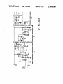
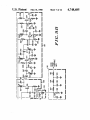
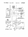
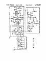
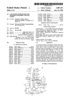
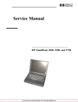
1
United States Patent [191
[11]
[45]
Rozanski, Jr.
[54] MOBILE RADIO COMMUNICATIONS
4,748,685
Patent Number:
Date of Patent:
May 31, 1988
Primary Examiner-Robert Lev
SYSTEM
Attorney, Agent, or Firm-Steven G. Parmelee
[75] Inventor: Walter J. Rozansld, Jr., Hurst, Tex.
[73] Assignee: Motorola, Inc., Schaumburg, Ill.
[21] Appl. No.: 917,923
[22] Filed:
Oct. 10, 1986
[57]
ABSTRACT
A vehicle mounted mobile transceiver (11) communi
cates via a secondary mobile unit (51) with a short range
portable unit (10). The portable unit (10) can be either a
cordless microphone or a transceiver. The portable unit
[51]
Int. Cl.4 ............................................. .. H01B 1/16
(10) allows a remotely positioned operator to transmit
[52]
U.S. Cl. . . . . .
messages to a base station (13). To ensure security and
[58]
Field of Search .................... .. 379/63, 68; 455/‘33,
. . . . . . . .. 455/218; 379/63
455/218, 35, 221, 212; 381/94
[56]
References Cited
U.S. PATENT DOCUMENTS
3,092,772 6/ 1963
3,614,321 3/1969
3,921,074 11/1975
Dalton et a1. ..................... .. 455/221
Shaw et al. .... ..
455/221
Baird ...... ..
455/221
4,359,780 1 1/ 1982 Day .... ..
4,479,250
10/1984
Flood
455/ 222
. ... ...
. . . . . ..
455/ 213
4,525,867 6/1985 Shiratani ................... .. 455/ 194
4,541,118 9/1985 Eastmond et a1.
....... .. 455/35
4,600,922 7/1986 Dunkerton et a1. ..
.. 340/825.44
4,627,101 12/1986 Anderson et a1. ................ .. 455/194
OTHER PUBLICATIONS
Motorola Service Manual 58P8l0l0C09A, “PAC-RT”,
Portable/Mobile Vehicular Repeater System.
reliable operation, the portable and vehicle mounted
units use digitized codes for ID and instruction pur
poses. These codes are newly generated from time to
time by the vehicle mounted unit and are imparted to
the portable unit via a battery charging interface. An
improved remote squelch detect is also provided. The
improved remote squelch detect substitutes the normal
input to the vehicle primary mounted mobile trans
ceiver (11) squelch gate for an audio signal. The remote
squelch detect can then detect the presence or absence
of this input signal at the output of the audio PA for the
vehicle mounted mobile transceiver, and this detection
can be used to enable the secondary mobile unit to
repeat the incoming message to the portable unit. With
less delay than the prior art methods.
4 Claims, 16 Drawing Sheets
121
132
[122 f
PRESELECTOR
rue-1&7
x
'F
I129 131
FlLTER/LlMlTER
DISCRIMlNATOR
X
.
124
FIRST
LOCAL
OSCILLATOR
VOICE
133
DATA
12a
SECOND
LOCAL
OSCILLATOR
AUDIO
PROCESSING “f OUTPUT
DATA
mocsssmc T°13aoun=ur
E
US. Patent
May 31,1988
Sheet 3 0f 16
4,748,685
EMERGENCY
22
FIG.4
21
27
27
28
29
FIG.6‘
31
, US. Patent
May 31,1988
Sheet 4 of 16
4,748,685
FROM SECONDARY MOBILE
UNIT BATTERY CHARGING
UNIT
/
\
DATA
TRICKLE
RESET CHARGE
302
BATTERY
CHARGING
UNIT
B01
r.
_ _ _
DATA RESET
I WATCH ooc_‘<— - —
TIMER
k...‘
PORTABLE uNn
— — —
._ L
799
- —>r-ALARM_.
MICROPROCESSOR
L......]
304
109
VOICE
TRANSMITTER
I
l
LEATA_I___
J
|
802
________.1RECEIVERI
FIG.'7
——
US. Patent
S
f 16
mop
W
R:
E5M2 .
weme
#ww
20-6
omEziowa
man,
M
mR19n?N8
H<my
RN.
5.
ZAQEB E
\\v,»
,MQ5KBHEQUEBLE
No’
Pop
5
4,748,685
US. Patent
May 31,1988
1
:L_=;_ J
iim5|HE
2012
|_ _
Sheet 6 of 16
F9AIG.
8
I
"'
L
J-lj
I
=17-1r
|
116
I
177'?
‘6163172 166r_153
168'
103
I
17‘-»164
5r.l
\
167 162
asif
152
154161157
159%
i.Q
It@151
—+
102
4,748,685
US. Patent
May 31,1988
Sheet 8 of 16
4,748,685
US. Patent
May 31,1988
Sheet 9 of 16
4,748,685
T0 AU
I
l
CONTROL
I’ 701
INPUT
SECONDARY
MOBIL
TRANSCE
Y~—»
>i
I
1 1 _'_
|/——
‘
702
DISCRIMINATOR
'‘
I
I
707
732
l_ _ '_"
I
‘
714
‘
[ 711
I
‘A o
706
‘ SQUELCH
/
GATE
<—-——--———a/L 713
704
708
L _
--
-—0
)1
705
\}
CONTROL HEAD
AUFQ'O
PRIMARY MOBILE UNIT
Au
5V
SIG
SOURCE
709
718
712
726
7:0
SPEAKER
727
m
‘
731
+
728 ' '1" 729 v °—-> TRANSMIT
FIG. 1 0
REF
ENABLE
US. Patent
May 31,1988
Sheet 10 of 16
4,748,685
[126
I
4
[124
@41
%
43__l9 L. _
in?
_
1FI2GA-
US. Patent
May 31,1988
Sheet 11 of 16
4,748,685
US. Patent
May 31,1988
Sheet 12 of 16
4,748,685
1601 \I_ _ __ __ _|
I 601
I
~" 602
I
I 601
L“_-'__J FIG. 1 3
FIG. 14
US. Patent
May 31,1988
Sheet 13 of 16
4,748,685
CODE
GENERATION
F
1t
' I
1 D01
PORTABLE INTERCONNECTION
SENSED
GENERATE NEW CODE
1 1002
TRANSMIT NEW CODE
r1005
PORTABLE DECO1DES AND
BUFFERS NEW CODE
1006
CODE
PORTABLE
TRANSFER
CONNECTED
COMIZLETE
NO
1007
1
USE OLD CODE
11003
NEW CODE ACCEPTED
‘
1 100a
TRICKLE CHARGE CONTINUES
1011
VERIHEQNBT‘JBIETJRSEINEDWS CODE
FI G. 1
I
1006
US. Patent
May 31,1988
Sheet 14 of 16
4,748,685
[ID14
MOBILE CONFIRMS
NEW CODE
1101s
'
1
1.105111 SENDS
BAD CODE SIGNAL
MOBILE AND PORTABLE
I
USE NEW CODE
PORTABLE UNIT
OPERATION
I
FI G. 1 '7
[1101
MICROPROCESSOR OFF
MICRO
.
PROCESSOR
sTRgBED
f11os
TRANSMIT PTT CODE
FOR 2 SECONDS
EMERGENCY
1103
1107
PTT
STILL
YEs
CLO?SED
N
[1104
TRANSMIT EMERGENCY
CODE FOR 10 SECONDS
r
’
CONTINUE SENDING PTT CODE
I
I
[1107
‘ CONCLUDE TRANSMISSION I
I
US. Patent
May 31,1988
INCREMENT COUNT 1
Sheet 15 0f 16
4,748,685
901
YES
I 903
TRANSMIT RANGE BURST
I904
CLEAR COUNT 1
FIG. 18
MESSAGE
FLAG SET
?
f 903
N0
INCREMENT COUNT 2
914
PORTABLE
ACKNOWLEDGE
RECEIVED
YES
I911
NO
+1912
+Jf913
CLEAR MESSAGE FLAG
CLEAR COUNT 2
TERMINATE MISSED
MESSAGE SIGNAL
1
'
,
TRANSMIT MISSED
MESSAGE SIGNAL
‘
US. Patent
May 31,1988
Sheet 16 0f 16
4,748,685
I 922
INCREMENT COUNT 1
I
CLEAR OUT OF RANGE FLAG
[927
CLEAR COUNT 1
H
7
I924
] SET OUT OF RANGE FLAG l
0-——(
I 929
931
MISSED
MESSAGE
SIGNAL lgETECTED
I933
ALARM
1
FIG. 19
1
4,748,685
MOBILE RADIO COMMUNICATIONS SYSTEM
TECHNICAL FIELD
This invention relates generally to RF communica
tions systems, and particularly to mobile radio systems.
The invention also relates to portable radios that may be
used with such a mobile radio system.
BACKGROUND ART
RF communications systems are well known in the
art. In many such systems, as in public safety applica
tions, vehicles are equipped with mobile transceivers
that allow public safety of?cers to communicate with
2
to be manufactured and operated in a relatively inex
pensive manner. In a transmit only con?guration, the
portable unit essentially operates as a cordless micro
phone. If desired, a public address system can be pro
vided on the vehicle to allow return messages to be
audibly broadcast to the portable user. In a transceiver
con?guration, of course, return messages could be re
turned directly to the portable unit via a two-way link
with the secondary mobile unit.
The portable unit includes a battery to support its
portable function. To reduce maintenance and enhance
reliability, the battery can be regularly recharged. The
secondary mobile unit can have a battery charging cir
one or more base stations and also with other similarly 15 cuit that functions to recharge the portable unit battery
equipped vehicles in the system. Such a mobile based
whenever the portable unit is connected thereto.
system typically includes a vehicle mounted trans
To ensure that the secondary mobile unit and the
ceiver, a microphone, a control head, and an antenna. In
portable unit recognize the legitimacy of each other’s
addition, a base station communicates with the vehicle
communications, subaudible digital codes are transmit
mounted equipment and typically serves as a message 20 ted therebetween as necessary. To minimize mainte
dispatch center. As the situation may require, repeaters
may be provided to extend the effective range between
nance, these codes are freshly generated and exchanged
each time the portable unit and the secondary mobile
the mobile and base station, all as well understood in the
unit are physically joined. In one embodiment, these
art.
The above con?guration works well, so long as the 25 codes are generated by the secondary mobile unit and
transmitted to the portable unit via the battery charger
public safety of?cer (or other individual) remains in the
circuit. In another embodiment, the battery charger
vehicle. Once the of?cer moves beyond the operational
circuit
can be controlled to allow a microprocessor in
range of the microphone, however, the of?cer typically
the secondary mobile unit to reset a microprocessor on
loses the ability to forward communications to the base
station. Since the range of the microphone will usually 30 board the portable unit. When both the portable unit
be governed by the length of the microphone cord, and
and the secondary mobile unit are transceivers, the
since this cord must usually be relatively short, commu
possibility exists that the portable unit may move out of
nications remote from the vehicle are usually rendered
range of the secondary mobile unit, and that an incom
dif?cult if not impossible.
ing message may be missed or that an outgoing message
To meet this problem, portable transceivers can be 35 may be prevented. To resolve this, in one embodiment
used to allow the of?cer to be able to communicate with
the secondary mobile unit occassionally broadcasts a
the base station when separated from the vehicle. The
range burst signal. If the portable unit does not receive
portable transceiver must, in order to be effective, emu
such a range burst signal with a predetermined period of
late the vehicle mounted system in all relevant aspects,
time,
an out of range alarm can be provided by the
including frequency capabilities, power rating, and sig
portable
unit to the user.
nalling capabilities. In effect, a public safety service that
In another embodiment, the portable unit can be con
implements this system must provide two wholly and
independently functioning radio systems for each of its
vehicles. Though this adequately supports the desired
?gured to provide an acknowledge signal upon receiv
ing a message from the secondary mobile unit. If the
communication function, this solution also represents a 45 secondary mobile unit does not receive such an ac
relatively costly approach.
knowledgement, it will broadcast a missed message
There therefore exists a need to provide relatively
signal. When the portable unit moves back within
inexpensive, effective, and reliable communications for
range, it will receive the missed message signal and
public safety of?cers and others who ordinarily make
provide a missed message alert to the user. The user can
use of a vehicle mounted transceiver but who must also 50 then take appropriate action to ascertain the contents of
carry out operations away from the vehicle from time
the message.
to time.
SUMMARY OF THE INVENTION
These needs and others are substantially met through
provision of the improved mobile radio communica—
In yet another embodiment, the squelch gate for the
primary vehicle mounted mobile transceiver can be
monitored, in a non-invasive way, to allow appropriate
enabling of the secondary mobile unit when transmit
ting messages received by the primary vehicle mounted
tions system disclosed herein. This system makes use of
mobile transceiver from the portable transceiver unit.
a relatively short range portable transmitter (or trans
To facilitate this, a predetermined audio signal can be
ceiver, as the case may be) that directly communicates
with a secondary mobile unit. The secondary mobile 60 routed through the squelch gate in the primary mobile,
and the output to the speaker for the primary mobile
unit in turn communicates with the primary vehicle
can then be monitored for presence of this predeter
mounted mobile transceiver. The secondary mobile unit
mined audio signal. When receiving a viable signal, the
functions to ensure the propriety of communicating
with the portable unit, and then acts in concert with the . squelch gate for the primary mobile will be closed, and
primary mobile unit like a repeater to allow communi 65 hence the predetermined audio signal can be detected.
cation between the portable and the base station.
When detected, the transmit function for the secondary
The short range needs of the portable unit minimize
mobile unit can be enabled to allow transmission of the
power requirements, and in part allow the portable unit
signal being received by the primary mobile.
3
4,748,685
4
MHz, 171.045 MHz, 171.105 MHz, 171.845 MHz, or
BRIEF DESCRIPTION OF THE DRAWINGS
171.905 MHz). The maximum output power cannot
exceed 50 milliwatts, and the maximum emission band
These and other attributes of the invention will be
width cannot exceed 54 kHz. It should be noted that
come more clear upon making a thorough and complete
study and review of the following description of the 5 these particular frequencies may give rise to data recep
tion problems, since adjacent frequencies can be used
best mode for carrying out the invention, particularly
for hydrological and meteorological data transmissions
when reviewed in conjunction with the drawings,
as used by the power, petroleum, forest products, busi
wherein:
ness, and railroad radio services. Therefore, care must
FIG. 1 comprises a block diagram depiction of the
invention;
10 be taken to ensure that the portable unit (10) will not
only meet the above noted speci?cations, but that the
FIG. 2 comprises a block diagram depiction of the
system will also remain relatively immune to interfer
invention;
ence problems from adjacent channels.
FIG. 3 comprises a block diagram depiction of the
Referring now to FIG. 3, the secondary mobile unit
interface between the secondary mobile unit and the
vehicle’s communication system;
15 (51) that interfaces between the portable unit (10) and
the primary mobile unit (11) essentially comprises a
FIG. 4 comprises a perspective view of the portable
radio receiver (or transceiver when used with a porta
unit;
FIG. 5 comprises a bottom plan view of the portable _
ble transceiver as explained below in more detail). In
unit;
practice, the secondary mobile unit (51) can be
FIG. 15 comprises a schematic diagram of the battery
charging and interface circuit;
an emergency code, to be broadcast to the base station
FIG. 6 comprises a detailed perspective view of the 20 mounted, for example, inside the housing or another
radio interface product such as a Systems 90 module
battery charging hub;
(52) (model number HLN106) as manufactured by Mo
FIG. 7 comprises a block diagram depiction of the
torola, Inc. The Systems 90 module (52) connects be
portable unit;
tween the primary mobile unit microphone (53) and the
FIG. 8 comprises a block diagram depiction of a
25 primary mobile unit (11) via the microphone input port.
transmitter suitable for use in the invention;
The systems 90 module (52) adds two primary fea
FIGS. 9(a)-9(c) comprise a schematic diagram of the
tures to a mobile system. First, the Systems 90 module
transmitter;
(52) causes the primary mobile unit (11) to broadcast a
FIG. 10 comprises a schematic depiction of the trans
subaudible digital signal comprising a unique ID code
mit enable feature of the invention;
FIG. 11 comprises a block diagram depiction of a 30 every time the operator closes the push-to-talk (PTT)
switch on the microphone (53). In this way, a base
receiver suitable for use in the invention;
station (13) equipped to decode the ID code can iden
FIGS. 12(a) and 12(b) comprise a schematic diagram
tify the mobile it is communicating with, and maintain a
of the receiver;
record of such proceedings. Second, the Systems 90
FIG. 13 comprises a schematic diagram of interface
switches for use in the secondary mobile unit;
35 module (52) can detect switching of an emergency
switch (50). When switching is sensed, the Systems 90
FIG. 14 comprises a schematic diagram of a watch
module (52) will cause the ID code for the mobile, plus
7 dog circuit;
FIGS. 16(a) and 16(b) comprise a ?ow chart of the
new code generation and transfer process;
FIG. 17 comprises a flow chart of portable unit oper
ation under certain operating circumstances;
FIG. 18 comprises a flow chart of secondary mobile
unit operation under certain operating circumstances;
and
FIG. 19 comprises a ?ow chart of portable unit oper
ation under certain operating circumstances.
(13) for at least a predetermined period of time, or until
the base station (13) acknowledges receipt of the signal.
In this way, an operator can press the emergency switch
(50), and the primary mobile unit (11) will broadcast
this call for help to the base station (13) regardless of
what else the operator may do. As will be shown below,
45 the secondary mobile unit (51) can interface with such a
module (52) and thereby allow the portable unit (10) to
have bene?t of such features as well.
Referring now to FIG. 4, the secondary mobile unit
can be seen as generally depicted by the numeral 51 and
50 as con?gured in conjunction with a Systems 90 module
BEST MODE FOR CARRYING OUT THE
INVENTION
(52). The secondary mobile unit (51) includes generally
an antenna (54) (which may be comprised of the micro
Referring now to the drawings, and in particular to
phone cord (54) for the primary mobile unit (11)), a
FIG. 2, the invention can be seen to comprise a portable
receiver (120), a secondary mobile unit microprocessor
unit transmitter (10) (or transceiver, as the case may be,
and as explained in more detail below) that communi- 55 (1701), a battery charging unit (1731), and a watchdog
cates with a secondary mobile unit (51) that mounts in a
timer (1732).
As will be described below in more detail, the re
vehicle (12). The secondary mobile unit (51) connects to
ceiver (120) receives both voice and data signals from
a primary mobile unit (11) that in turn communicates
the portable unit (10) and then functions to separate
with a base station (13). In effect, the primary and sec
ondary mobile units (11 and 51) function as a repeater to 60 these signals to thereby provide the voice signal (702)
directly to the Systems 90 module (52) where it can
connect the portable unit (10) to the base station (13).
serve as the audio input to the primary mobile unit (11).
In an application where the portable unit (10) in
The data signals (1703) from the portable unit (10) are
cludes only a transmitter and effectively comprises a
provided to the secondary mobile unit microprocessor
cordless microphone, the portable unit (10) must meet
certain FCC requirements governing operation of such 65 (1701) (provided, for example, through use of an
a device in the United States. For example, the portable
unit (10) can only transmit on one of eight frequencies
(169.445 MHZ, b 169.505 MHz, 170.245 MHZ, 170.305
MC146805F2 as manufactured by Motorola, Inc.).
The microprocessor (701) functions to decode and
act upon the incoming data signals and will function
5
4,748,685
6
either to enable a PTT switch in the Systems 90 module
(51) to transmit data to the portable unit microprocessor
(52) by providing an enable PTT signal (1704) or to
enable transmission of an emergency signal via the Sys
tems 90 module (52) through provision of an enable
(801), as described below in more detail.
In an alternative embodiment, the portable unit (10)
can be con?gured as a transceiver having a receiver
emergency signal (1706). The microprocessor (1701)
(120) that receives signals transmitted by the secondary
can also provide encoded data and reset signals as de
mobile unit (51) and that demodulates these received
scribed below to the battery charging unit (1731) for use
in providing new communication codes to the portable
unit (10).
Finally, the watchdog timer (1732) may be utilized to
assure regular proper operation of the microprocessor
sor (801) and voice signals to an appropriate audio
transducer system (802).
In another embodiment, the portable unit (10) can
include additional buttons in the input unit (303) as
signals to provide data to the portable unit microproces
(1701) in accordance with well understood prior art
desired to facilitate remote control of other desired
functions, such as a public address system on board the
vehicle, ?ashing lights on the vehicle, sirens on the
vehicle, and the like.
technique.
Referring now to FIG. 5, the portable unit (10) can be
housed in a small plastic housing (21) having a belt clip
(22) to allow easy mounting of the portable unit (10) on
the person of the operator. The portable unit (10) also
includes a PTT button (23), an emergency button (24),
and a microphone (26). A loop antenna, such as those
Referring now to FIG. 9, a block diagram depiction
of a transmitter suitable for use in the portable unit (10)
(or in the secondary mobile unit (51) when the latter is
con?gured as a transceiver) can be seen as generally
used in personal pagers, can be concealed on the inside 20 depicted by the numeral 100. The transmitter (100)
includes generally a microphone (101), a ?rst ampli?er
of the housing (21).
(102), a limiter/deviation adjustment unit (103), a sum
mation node (104), a frequency modulatable oscillator
(106), a second ampli?er (107), a ?lter (108), and an
antenna (109). The ?rst ampli?er (102) serves to amplify
In addition, and with reference to FIG. 6, two battery
charging ports (27) can be provided through the hous
ing (21) to allow access to a battery (and other circuitry
described below). To complement the charging ports
(27), a battery charging HUB (28) (FIG. 7) can be pro
vided having a cavity (29) formed therein for receiving
the portable unit (10) and having appropriate conduc
audio signals provided by the microphone (101), which
ampli?ed signals are then passed to the limiter/devia
tion adjustment unit (103) to properly prepare the audio
signal for modulation and subsequent transmission. The
processed audio signal is then summed with data signals
from the relevant microprocessor at the summation
node (104) and utilized to modulate the oscillator (106).
The modulated carrier signal then passes through the
second ampli?er (107) and output ?lter (108) to the
antenna (109) that broadcasts the signal.
tors (31) disposed therein that mate with the charging
ports (27) of the portable unit (10). The battery charging
HUB (28) can be operably con?gured in conjunction
with the secondary mobile unit (51) as described below
in more detail.
Referring now to FIG. 8, the portable unit can be
seen as depicted generally by the numeral 10. The por
table unit (10) includes generally a portable unit micro
Referring now to FIGS. l0a-10c, a more detailed
description of the transmitter (100) will be described.
The microphone (101) can be provided through use
processor (801), an input unit (303), a battery charging
unit (302), a transmit enable unit (304), a transmitter
(100), a microphone (101), and an antenna (109).
of a crystal microphone such as an MK 1301 (when
using the transmitter (100) with the secondary mobile
The portable unit microprocessor (801) receives input
unit (51), one would of course substitute an appropriate
signals from the input unit (303) as operated by the
operator. The input unit (303) comprises the PTT but
audio signal coupling mechanism to allow input of the
primary mobile unit (11) audio signal output). The out
ton (23) and the emergency button (24) referred to
put of the microphone (101) connects to an ampli?er
stage (102), essentially comprised of a buffer section and
switches by causing the transmit enable unit (304) to
an ampli?cation section. The buffer section includes a
enable the transmitter (100). In the ordinary operating
9642 transistor (151) having its emitter connected to
mode, the microprocessor can literally be turned off in
ground and its collector connected through a 5.1 k ohm
order to minimize current drain and extend battery life.
resistor (152) to a switched voltage source (153) and
When the operator pushes either button, related cir
also through a 100 k ohm resistor (154) to the base
cuitry activates the microprocessor and strokes an inter
thereof. The base of this transistor (151) also connects to
rupt to cause the microprocessor to determine which
ground through a 100 k ohm resistor (156), and through
button was pushed and to react accordingly. If the PTT
a 0.02 microfarad capacitor (157) to the output of the
button has been pushed, an appropriate PTT code is
microphone (101). In addition, the output of the micro
transmitted subaudibly by the portable to the mobile for 55 phone (101) connects to a 2.2 k ohm biasing resistor
a predetermined period of time, such as two seconds.
(158) and an appropriate grounded ?lter capacitor
This allows the mobile to identify the portable (this
(159).
above. The microprocessor (801) responds to these
normally requires around 642 milliseconds), and for the
The collector of the transistor (151) connects through‘
base station to decode and acknowledge the mobile. If
a 2 microfarad coupling capacitor (161) to a voltage
the PTI‘ button remained closed beyond the two sec 60 divider comprised of a 47 k ohm resistor (162) and an 11
onds, the portable continues to send the PTT code.
k ohm resistor (163), and also to the base of a 9648
Otherwise, a termination of message signal may be sent.
transistor (164). The emitter of this transistor (164) con
The battery charging unit (302) allows a battery (not
nects to a 91 ohm resistor (166). The collector of this
shown) to be charged when the portable unit (10) is in
transistor (164) connects to a 3.3 k ohm biasing resistor
the battery charging hub (28) described above. The
battery charging unit (302) also allows the portable unit
microprocessor (801) to be reset by the secondary mo
bile unit (51) and to allow the secondary mobile unit
65
(167), and through a 0.1 microfarad coupling capacitor
(168) to the limiter/deviation adjustment stage (103).
The limiter/deviation adjustment state (103) includes
two grounded parallel con?gured back-to-back diodes