1
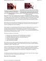
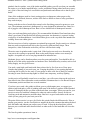
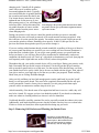
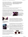
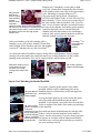
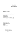
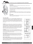
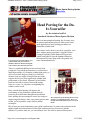
Standard Abrasives - DIY Cylinder Head Porting Guide
Page 1 of 13
Motor Sports Racing Update
Enter Here
Head Porting for the DoIt-Yourselfer
by the technical staff of
Standard Abrasives Motor Sports Division
Here's an interesting head porting fact: In many cases,
the greatest performance gain per dollar spent comes
upon application of basic porting procedures to a
production cylinder head.
It is easy for the do-it-yourselfer to port
cylinder heads. All you need is the
Standard Abrasives Deluxe Porting Kit,
some common tools and some free time.
These basics can be done by any do-it-yourselfer, even
those with no porting experience, using the Deluxe
Porting Kit and the Gasket Removal Kit (part nos.
260001 and 260005) from the Standard Abrasives
Motorsports Division, along with a die grinder and
some common hand tools.
There is a significant difference between basic head
porting for a street-high-performance or weekend racer
application and the very complex cylinder head work you
see in a Pro Stock drag race motor or a NASCAR
Winston Cup race engine. Doing full-on race heads
requires the services of an experienced cylinder head
professional, so Pro Stock, Winston Cup and similar
heads are best left to experts. Basic head porting,
however, is easy...so easy that even beginning hot
rodders can do it well.
Basic cylinder head porting will improve the
performance of any production cylinder head by
removing flaws that come through mass production.
Basic porting does not attempt to correct any design or
engineering deficiencies. Once your porting project turns
to that, you're beyond the scope of basic porting
techniques.
The components of the Porting Kit are neatly
packed in a compartmented box. There are
enough abrasive materials to port a set of V8
heads.
Why is basic port work important to your engine's performance? It reduces the restriction in the
engine's intake and exhaust tracts. Reduce that restriction and you let more air into the
cylinders. If you have more air, you can add more fuel. The result is increased horsepower.
http://www.sa-motorsports.com/diyport.shtm
12/15/2004
Standard Abrasives - DIY Cylinder Head Porting Guide
Page 2 of 13
A more significant point of restriction is where the intake or
The area of the valve guide that protrudes into exhaust port floor curves down to meet the valve seat. Called
the intake or exhaust port is always a place
the "short side radius," it is also a place where sharp edges
where sharp edges and restriction to flow are
and roughness pose a threat to flow. In this cutaway of a
found. A basic porting project seeks to smooth production cylinder head, the short side radius has not one but
those sharp edges.
two very sharp edges.
Most of the work in a basic porting project is focused on reducing those restrictions which are
caused by: 1) "steps" that may obstruct intake air flow as it transitions from the intake manifold
to a smaller intake port entry in the head; 2) casting bumps, ridges or other marks, such as those
you may find on port floors or roofs; 3) sharp edges, such as those you will find around the
valve guide bosses at the top of the valve pockets; and 4) the point where the intake port floor
curves down to the valve seat.
Basic porting, while somewhat time consuming, is not hard work. It takes about 10-12 hours to
do a set of average V8 heads. Some week nights and a weekend invested in your heads and
your basic porting project will be complete.
Time is money, so we are not going to tell you doing your own heads will save a lot; however,
most professional cylinder head porting businesses will charge $400-$600 for what is
sometimes known in the trade as a "street/strip" port/polish job. Your basic porting project,
done with the Standard Abrasives Porting Kit, will allow you to spend that $400-$600 on some
other performance enhancement you want.
The project is made up of six sub-tasks:
1.
2.
3.
4.
5.
6.
Intake port entry enlargement, surface finishing and port matching.
Smooth the intake short side radii, valve guides and valve pockets.
Smooth the exhaust short side radii, valve guides and bowls.
Exhaust port and bowl polishing.
Combustion chamber polishing.
Intake manifold port matching.
Five of these six tasks reduce restriction in the intake and exhaust tracts. The remaining step,
polishing the combustion chambers, inhibits carbon build-up, decreasing an engine's tendency
to detonate or "knock" under heavy load.
After we touch on materials, tools and safety precautions, we are going to walk you through the
specifics of a basic port job. As an example, we'll port a standard cast iron head as used on a
5.0-liter Chevrolet Small-Block V8; however, all basic porting techniques can be applied to the
head or heads on any engine, regardless of its manufacturer, configuration or number of
cylinders.
To illustrate the improvement that comes with basic porting work, at the end of this web page,
we'll post flow test results, both before and after porting,
Materials, Tools and Safety
http://www.sa-motorsports.com/diyport.shtm
12/15/2004
Standard Abrasives - DIY Cylinder Head Porting Guide
Page 3 of 13
The first items you need are our Standard Abrasives Deluxe Porting Kit
and our Standard Abrasives 3-inch Gasket Removal Kit. These contain
all the abrasive products required to perform a basic porting job on a
pair of cast iron or aluminum cylinder heads.
This display shows all the
items one needs to port a
set of heads the easy,
Standard Abrasives way.
The components in these kits are designed for mounting in a die
grinder having a maximum speed of 18,000-20,000 rpm and a 1/4-in.
diameter collet or "chuck." Do not use an 1/8-inch collet grinder of the
type used in hobby or arts and crafts work.
An air-powered die grinder is desirable because
of its relatively low cost and variable speed. An
air grinder will require a compressed air source.
Most compressors powered by motors rated at
2.5 horsepower or more will work well. The air
system should be equipped with an adjustable
pressure regulator. The abrasive products'
maximum safe speed is 18,000-20,000 rpm. If
an air grinder's maximum rpm exceeds that, you
must reduce the air pressure with the
regulator so that speed is not exceeded.
While the never-exceed speed is 18,000-20,000
rpm, best durability of the abrasive products is
achieved when the grinder runs at 10,00012,000 rpm. Obviously, measuring the die
grinder's speed is difficult; however, most tool
manufacturers cite the maximum speed either in
the unit's instructions or on a specification plate
attached to the tool. Suppose maximum speed
of your unit is 20,000 rpm, but you want to run
it at 10,000. Operate the grinder at half throttle
and listen to the noise it makes. Then, run it at
full throttle and adjust the pressure regulator
such that the noise is about the same as before.
That will approximate 10,000 rpm.
This particular air compressor has a built-in pressure
regulator. The pressure control on the panel selects
the regulated pressure. The gauge on the panel reads
regulated pressure not the tank pressure. If you use
an air grinder, whatever compressed air source you
use should have an adjustable regulator.
The pressure regulator is important for another
reason. You hold a die grinder in both hands,
one on the rear of the tool and the other on the
front of the unit. The front hand controls the
grinder and operates the throttle. It is easier to
manipulate a die grinder with the throttle wide
open than it is to both control the grinder and
modulate the throttle at the same time.
You may be using an electric die grinder. That is acceptable as long as its maximum rpm is
below the 18,000-20,000 rpm limit. Because electric grinders are often capable of exceeding
that by a significant margin, an electrical device allowing the user to reduce the tool's speed is
necessary. Additionally, speed regulation of an electric grinder will be necessary if you want to
use the abrasives at 10,000-12,000 rpm.
Additional tools and materials required are: A 5/64-in. hex key (Allen wrench), the die
http://www.sa-motorsports.com/diyport.shtm
12/15/2004
Standard Abrasives - DIY Cylinder Head Porting Guide
Page 4 of 13
grinder's chuck wrenches, a set of the intake manifold gaskets you will use when you assemble
the engine, a set of intake manifold bolts, a scribe, machinist's bluing (either brush-on or sprayon), a pair of four-inch long 2x4 wood blocks and junk intake and exhaust valves that fit your
heads.
None of the techniques used in a basic porting project are dangerous when proper safety
procedures are followed; however, misuse of the tools or failure to observe safety procedures
may result in injury.
Porting work throws lots of metal chips around, so the first thing you need to protect are your
eyes. The minimum protection is shatterproof eye wear designed for industrial use. Better is a
set of goggles with a shatterproof lens. Best is a face shield made of shatterproof material.
Next, you need snug-fitting work gloves. We recommend the Mechanix Wear brand since they
allow a good sense of touch while still offering protection. An alternative is a generic leather
work glove of medium thickness. Avoid thin leather gloves or the very thick units intended for
welding. Do not use rubber gloves.
The last two pieces of safety equipment are optional but suggested. People sensitive to airborne
dust may want a respirator mask such as the type used by paint and body shops. These
inexpensive, white cloth masks are held to your face with an elastic string.
The noise some air grinders make is quite loud. If the loud power tools are a discomfort, do
your port work wearing ear protection. Best are the muffs airport workers wear around jet
engines. Acceptable are a set of ear plugs intended for industrial use.
Mechanix gloves can be found anywhere racers buy parts and supplies. You should be able to
find the rest of this safety equipment at a hardware store. Dedicated safety vendors, such as Lab
Safety Supply, are also good sources.
You need a waist high work bench with about a three-foot by five-foot area of clear space.
Consider the lighting of your work area, too. Gauging the quality of your porting depends on
you being able to easily see the work. If your garage or other work area is dimly lit, consider
investing in some fluorescent shop lights or at least some temporary, auxiliary lighting.
As this project will probably extend over several days, you will want to clean up the work area
from time to time. Know that under certain conditions, aluminum dust is a fire hazard. Dispose
of aluminum particles and dust in a covered container.
If you have never used a die grinder to deburr, port or polish engine parts, we suggest you
obtain a junk head and try a bit of grinding with some of the abrasive products in the Standard
Abrasives Porting Kit before you start on the heads from your engine. What you want for your
practice session is a head that is damaged or otherwise unserviceable. Sources for this are
wrecking yards and automotive machine shops. Best bet is to get a head similar to the one on
which you are going to do your basic port work.
The point of this exercise is to get a feel for the die grinder fitted with different tools. Prior to
starting your practice, use the wood blocks to support the head in a manner that makes the head
deck and intake and exhaust port surfaces easy to reach. Lift up the head and place a block
between your work bench and a head bolt boss or other surface of the head that will sit on the
block.
The first die grinder operation to learn is
http://www.sa-motorsports.com/diyport.shtm
12/15/2004
Standard Abrasives - DIY Cylinder Head Porting Guide
Page 5 of 13
changing tools. Virtually all die grinders
come with a set of wrenches used to
loosen and tighten the chuck. Typically,
one wrench holds the air grinder shaft and
the second wrench turns the chuck's nut.
You loosen the nut, insert the tool, then
tighten the nut. In the process of your
basic porting project, you will change the
tool many times. Always disconnect the Tool changing is the first die grinder skill one learns. Most
air grinder from the air source and the
die grinders use the type of chuck that is tightened with two
open-end wrenches.
electric grinder from the power source
when changing tools.
During your practice work, learn to control the grinder such that you move it smoothly.
Grinding in one place will result in removal of too much material and uneven surfaces. Also,
this is the time to set the speed of the grinder. You neither want to exceed 20,000 rpm nor do
you want the grinder to chatter. Remember, best speed is 10,000-12,000 rpm. Review the
previous discussion about grinder speed if you need to change it.
If you are working with aluminum heads or intake manifolds, regardless of the type of abrasive,
use a more gentle touch than you would if you were working cast iron. Because aluminum is
softer than iron, it abrades faster. If you use the same grinder pressure you would with iron,
before you know it, you will have shaved off too much material. Additionally, under most
conditions, the abrasive tool will "load- up" with caked on aluminum as you work. Spraying the
tool frequently with a light lubricant, such as WD-40, reduces this problem.
Throughout this job, your quality control device will be your finger. During your practice work,
find a reasonably flat spot on the exterior of the head. Use the 40-grit then 80-grit cartridge
rolls to smooth a square-inch or so of this area. Use the exterior of the head because you want
your finished work to be easily visible. Strive for an even finish with the 80-grit. Then, take off
your gloves and use your finger tips to feel the area you have just prepared. Think carefully
about what you are feeling. Hold that thought.
After you feel confident you have had enough practice on the junk head, lay out the "good"
heads you will port on the bench. They need to be completely disassembled before any port
work is attempted. Consult a factory service manual if you are going to take them apart
yourself or have an automotive machine shop do it for you.
After disassembly, if the heads came off an engine that had been in service a while, they will
need to be cleaned. We suggest you have iron heads hot-tanked. If your heads are aluminum,
make sure whatever cleaning method you choose is safe for aluminum.
Used heads should be carefully examined for cracks, especially around the exhaust valve seats.
Additionally, used heads should be pressure checked to make sure they have no coolant leaks.
If leaks or cracks are found, have them repaired before doing any port work.
Step 1: Removing Old Gaskets and Marking the Intake Ports
Even after it was hot-tanked, this
cylinder head still has very dirty intake
gasket surfaces. Most used heads will
come out of the hot-tank or cleaning
bath this way. Note the sharp-edged
http://www.sa-motorsports.com/diyport.shtm
12/15/2004
Standard Abrasives - DIY Cylinder Head Porting Guide
Page 6 of 13
"step" formed by the corners of the port entry in the head.
Even though the heads have been cleaned, the gasket and deck surfaces should be conditioned
to remove all traces of old gaskets, paint, gasket sealer, corrosion and dirt. The use of a putty
knife or scrapper for this purpose is not acceptable because neither will clean those surfaces
completely. If your heads are aluminum, a putty knife or scraper may even damage those
surfaces.
The Standard Abrasives' 3-inch Gasket Removal Kit is the
proper way to condition the gasket surfaces without
damaging them. It contains surface conditioning discs for use
on cast iron and aluminum along with a holder pad that
attaches to your die grinder.
The solution is the Surface
Conditioning discs in Standard
Abrasives Gasket Removal Kit.
They abrade the surface down
to bare metal but do no damage
in the process.
Disconnect the grinder, install the Standard Abrasives'
surface conditioning disc holder into the chuck and tighten
the nut. The conditioning discs use Standard Abrasives'
unique Soc-AttTM locking system, so installation is as simple
as a twist of your wrist. Reconnect the grinder, put on your
eye protection and gloves, then start removing the gaskets
the easy, Standard Abrasives way. Once the gasket surfaces
are down to bare metal, disconnect the grinder and remove
the conditioning disc set-up.
In most cases, your port work will start with enlarging the "port entry" area to the size of the
openings in the intake manifold gaskets. Later, you will reshape the ports in the intake manifold
to this same size.
To ensure the head port entry and the intake manifold port end up the same size, you scribe an
outline of the intake gasket openings on the head and the manifold. Machinist's bluing is used
for this. Apply it to the intake gasket surface around the intake ports and allow it to dry. Place
the new intake gasket in its normal position and hold it with manifold bolts. Scribe the inside
perimeter of each intake port onto the gasket surface of the head, then remove the gasket.
Machinist's blue, in this case sprayon Dykem, is applied to the area
surrounding the intake port entries
in the head.
The intake manifold gaskets, in this
case a set of Fel-Pro Performance
Gaskets, are installed on the head.
Intake bolts hold them in place and
an outline of the inside of the
gasket's intake port is scribed on
the head.
The areas inside of the scribe
lines are the places where
material will be removed.
Pay close attention to the position of the gasket on the head. If it is upside down or backwards,
your scribe marks will be in the wrong locations. That will cause a serious problem with your
port work.
Step 2: Preparing the Intake Port Entry
http://www.sa-motorsports.com/diyport.shtm
12/15/2004
Standard Abrasives - DIY Cylinder Head Porting Guide
Page 7 of 13
Install the large, conical, rotary grinding stone (part no. 263901) from
the Porting Kit into the grinder's chuck. Tighten the chuck then
reconnect the air hose or electric cord. Remember to put your eye
protection back on if you remove it during the change.
The first porting operations
are usually done with the
rotary stone.
Now you are ready to do your first porting work. You will enlarge the
port openings in the intake gasket surface by removing material inside
of the scribe marks you made. Then, you'll blend or "feather" the now
larger port opening into the remaining port by removing progressively
less material as you move down into the intake port. In most cases,
you want to grind from the port entry to about 1-1.5 inches into the
port.
From your initial practice on the junk head, you know that the stone
removes large amounts of material rather quickly so pay attention to
When using the stone,
control of the grinder. It is better to go over the work with several
remember that 1) it removes light-to-moderate passes rather than doing one heavy pass, remove too
material quickly and 2)
much and possibly render the head useless.
smooth, controlled
movement of the grinder is
necessary.
Certain heads, such as Chevy small-block V8 units, have pushrod holes in close proximity to
the port wall, just downstream of the port entry. Enlarge the port entry too much and you will
grind into a pushrod hole. This may destroy the head or at least cause a very expensive repair.
Adequate work on the practice head will help you avoid that.
To see how far you can enlarge the port, go back to the junk head and grind one of its port
entries until you cut into the pushrod hole. After that, you will know how much you can grind
in that area without damaging the head.
Once you have removed the majority of material with the large stone, you may need to switch
to the small diameter, conical rotary stone (part no. 263061) to profile the small radii at the
corners of each port.
The most important thing to remember about rotary stones is they remove large amounts of
material. They are not for final surface finishing. There may be basic port projects that do not
require removal of large quantities of material. An example might be a production head on a
high-performance engine. Those heads may already have fairly large ports and you will find the
material to be removed inside the scribe marks is minimal. In that case, the rotary stones may
be unnecessary.
Disconnect the grinder, remove the stone and install the short cartridge
roll mandrel (part no. 269111). Cartridge rolls come in a variety of
sizes and shapes. The Kit includes straight rolls in two grits and three
diameters, half-taper rolls in two grits and two diameters and full-taper
rolls in two grits. Different grits are necessary to get the proper finish.
Cartridge roll work starts with 40-grit then switches to 80-grit. It is not
practical to go from a virgin surface or one that has been worked on
The Cartridge rolls in the
with the rotary stone to proper finish with only the 80-grit. It takes too Standard Abrasives
much time and you'd need more 80-grit rolls than there are in the Kit. Porting Kit come in a wide
variety of shapes and sizes.
Large-diameter, straight cartridge rolls are for finishing relatively flat
http://www.sa-motorsports.com/diyport.shtm
12/15/2004
Standard Abrasives - DIY Cylinder Head Porting Guide
Page 8 of 13
surfaces like port walls, floors and roofs. The small straight rolls are for
finishing long, radiused areas, such as the corners of intake ports, or
areas of convex curves such as the corners of the valve guide bosses or
the short side radii. The half-taper and full-taper cartridge rolls are
better used on surfaces with concave curves, such as the "bowl" areas
at the top of the valve pocket or combustion chamber corners.
Additionally, half- and full- taper rolls are better to use when the tool
Cartridge rolls also come
in two grits, 80 (left) and approaches the work from a steep angle, such as working on the valve
guide boss through the valve hole.
40 (right).
The cartridge roll mandrel has threads that hold the roll. Each roll has
an orange spot which is pointed at the grinder. All you do is push the
cartridge roll on the mandrel, then screw it tight.
With the mandrel in place and tightened, place one of the large, straight 40-grit cartridge
rolls (part no. 263161) on the end of it. Note the little orange spot on one end of the roll.
Point the spotted end towards the grinder, then screw the roll onto the mandrel.
Reconnect the air or power supply.
You start with 40-grit rolls and progress to 80-grit. In many intake
ports, the small-diameter rolls will be needed to finish the radii at the
corners of the port. Typically, you polish only 1-1.5 inches down the
port.
Begin finishing the flat areas in that first 1-1.5 inches past the port entry. Only work deeper in
the port if there are excessive bumps or casting flaws. Remember to feather the smooth area
into the surrounding virgin metal at the end of that 1-1.5-inches down the port entry.
Once you have worked the port entry with 40-grit, switch to the large, straight 80-grit cartridge
roll (part no. 263163). The 80-grit gives you the smooth, but not polished, surface that is
correct for intake ports. Once you finish the 80-grit step, stop, remove your gloves and feel the
surface. When your tactile "QC checker" senses the right finish on all the port walls, you're
done.
Best way
to gauge
the finish
on the
port walls
is with
your
finger. For intakes, you want the
surface slightly rough to the touch but
without waves, gouges or low spots.
At left is a finished intake port
entry. Note the slightly rough
finish. At right is a partially
finished port. The floor is
untouched and a large casting
mark is evident. Also, note the
difference in port heights. This
is because the left port has been matched to the gasket whereas
the matching of the right port has not been completed.
http://www.sa-motorsports.com/diyport.shtm
12/15/2004
Standard Abrasives - DIY Cylinder Head Porting Guide
Page 9 of 13
With this cutaway, we polished the whole port to better illustrate the rough-to-touch finish.
Note the smoothed valve guides and short side radius.
Step 3: Short Side Radius and Bowl Work
The point where the intake port floor curves down to the valve seat is known as the "short-side
radius." From an airflow standpoint, this area is the most critical in any port. Smooth that spot
and there usually is a significant increase in flow through the port.
(A) In this production
intake port, air starts into
the port flowing
smoothly. When it
encounters the casting
bump on the floor of the
port, smooth flow breaks
into tumbling and
turbulence. This causes restriction to the overall airflow
in the port.
(B) The turbulence in the airflow becomes more severe
as air passes the sharp edges of the short side radius in
this drawing. Smoothing the radius and removing
casting bumps and flaws reduces turbulence and
increases flow.
With most production heads, the short-side
radius will be sharp-edged and rough. The goal
is to soften those sharp edges and smooth the
roughness. Depending on the location of the
radius and how you are approaching it, you may
keep the short mandrel in the grinder or you
may need to switch to the long mandrel (part
no. 269149). Start with the small diameter, 40grit straight cartridge rolls (part no. 263021)
and, depending on the location of the radius and Bowl work is the second part of the basic porting.
the tool angles necessary to approach it, you
Here a half-tapered cartridge roll is used to smooth
may also need to use small, 40-grit, half-tapered the valve guide. While this picture shows work on an
exhaust port, the valve guide work is the same be it in
(part no. 263351); large, 40-grit half-tapered
an intake or an exhaust.
(part no. 263751) or 40-grit, full-tapered (part
no. 263301) cartridge rolls. Again, you start
with 40-grit and switch to 80-grit.
Short side radius work is the first time you will bring abrasives near the valve seat and that is
the one place you want to avoid hitting with any abrasive or rotating part of the grinder. Even
though you will have a valve job done to your heads once the port work is finished, it doesn't
take much of a hit on the valve seat to render it unusable even after a valve job.
The next step is to do the roofs of the valve pockets and the valve guide boss. Called "bowl
work", this will require a mix of the different small-diameter, tapered and straight cartridge
rolls. Remember to start with 40-grit and finish with 80.
The valve throat is the smallest diameter in
the valve pocket just above the valve seat. A
general rule is that the valve throat should be
http://www.sa-motorsports.com/diyport.shtm
In some cases, depending on
12/15/2004
Standard Abrasives - DIY Cylinder Head Porting Guide
about 85% of the valve diameter. If you
measure the throat to be smaller than that,
using a combination of the rotary stone and
cartridge rolls, open that diameter up to the
85% figure. If you attempt to open up the
valve throat, first practice the technique on
your junk head.
Page 10 of 13
port length and the position of the valve guide, it
may be necessary to switch to the long cartridge roll
mandrel and work on the guide through the intake
port entry or the exhaust port exit. A full-taper
cartridge roll works best for that.
Step 4: The Exhaust Port
Goals for the exhaust port are similar to those we achieved with the intakes: To reduce
restriction to gas flow, but your methods are going to be a bit different.
Exhaust gases carry combustion by-products, of which carbon is a component. Over time,
carbon deposits build up on the exhaust port walls and that can impede exhaust flow. To make
the port walls more resistant to carbon build-up, in the final step you will give the exhaust port
as smooth a texture as possible, a "near-mirror" finish, if you will.
The initial exhaust port work is very much
Initially, the exhaust port
like what you did to the intakes. The major
exits are worked just like the
part of the finishing and polishing will often
intake port entries; however,
be done with small-diameter, straight and
they are finished by
tapered cartridge rolls. Do the port exits,
polishing the full port and
bowls and valve guide work just like you did
using finer than 80-grit
abrasives.
on the intakes.
After cartridge roll work is
complete, you switch to the
Combination Mandrel and attach
the flap wheel.
Once you are done with the cartridge rolls, remove their
mandrel and install the Standard Abrasives Combination
Mandrel (part no. 269201) and screw the 120-grit flap wheel
(part no. 262618) onto it. The flap wheel is used to take the
finish one step past what you put on the intakes. Use the flap
wheel on every part of the exhaust port you can reach.
Once your flap wheel work is done, remove it and install one of
the small, hex-socketed set screws into the Combination
Mandrel. Tighten it, then screw one of the maroon-colored, 3You want to
ply, 1 1/2- inch, medium-grade, Cross BuffsTM (part no. 265054)
flap wheel all
onto the set screw. Standard Abrasives Cross- BuffsTM are the
accessible
most unique product in the Deluxe Porting Kit. They were
areas of the
exhaust port. designed exclusively for automotive use. Of all abrasives in the
Porting Kit, Cross Buffs TM are most sensitive to grinder speed
and should be run at 10,000 rpm for best results. Also, Cross
Buffs TM need to be used with a light lubricant, such as WD-40.
Begin working the exhaust port with the medium
The Cross
Cross Buff TM. Once you have hit as much of the port
BuffsTM in the
as you can with the medium, make a final pass with
Standard
the red, 3-ply, 1 1/2-in. very-fine-grade, Cross
Abrasives
BuffTM (part no. 265056). When you are done, the
Porting Kit come
in two grits;
exhaust port walls will have that near-mirror finish
medium and fine.
that will resist carbon deposits.
http://www.sa-motorsports.com/diyport.shtm
12/15/2004
Standard Abrasives - DIY Cylinder Head Porting Guide
TM
When flap wheel work is done, Cross Buffs are screwed onto the
an Allen stud goes in its place. Allen stud in the Combination
Mandrel.
Page 11 of 13
Use the Cross Buffs TM just like you did
the flap wheel; on all areas of the port
you can reach. A light oil must be used
with Cross Buffs TM.
In most cases, you never port match the exhausts. Many
stock exhaust manifolds and virtually all tube headers will
have larger port sizes than do the heads. You want that
"step" from the port to the larger header tube or exhaust
manifold because, as pressure pulses flow back and forth
in the exhaust system, it acts as a "reversion dam" by
resisting back flow of exhaust gases into the port. If you
end up with the rare situation where the stock exhaust
manifold has ports smaller than those in the head, you will
need to port match. Use the same technique used to match
the intakes.
This is a finished exhaust port.
Note the smoothed valve guide and
short side radius. Also, note the
finish is significantly different from
what we saw on the intake cutaway.
Step 5: Polishing the Chambers
You want to put the near-mirror finish on the combustion
chamber walls for two reasons: 1) As a deterrent to carbon
build-up; and 2) to eliminate any sharp edges that can cause
pre-ignition. The first thing to do is clean up the stems of your
junk valves (Cross Buff TM or one of the surface conditioning
discs will work well) then install the valves into the chamber
you will be working on. They will protect those all-important
valve seats as you polish the surrounding chamber surfaces.
Before doing the chambers, install
a set of valves to protect the valve
seats.
Spray the head deck with machinist's bluing, then install one of the head gaskets you will use to
assemble the engine. Scribe the outline of each chamber hole in the gasket on the deck.
Most important to remember during chamber work is that you want to remove as little material
as possible. Every bit of metal you polish away increases chamber displacement a tiny bit and
reduces your compression ratio a corresponding amount. For that reason, you must not use the
rotary stone for chamber polishing unless you need to unshroud the exhaust valves.
Nevertheless, you cannot polish the chambers with just Cross
Buffs TM. You must use the cartridge rolls first. Next, smooth the
sharp edges where the chamber meets the deck, but do not grind
past the line scribed around the chamber. You may need the
larger cartridge rolls for the chamber's flat surfaces.
http://www.sa-motorsports.com/diyport.shtm
Half-tapered
cartridge rolls
are best to
polish
chamber
corners.
12/15/2004
Standard Abrasives - DIY Cylinder Head Porting Guide
Page 12 of 13
Exhaust valve "shrouding" occurs when, at high
valve lifts, exhaust flow is impeded by the closeness
of the chamber walls to the edge of the open exhaust
This particular
valve. Shrouding is common with pre-1971
head did not
Chevrolet small- and big-block V8 and early
have an exhaust
valve shrouding
289/302 Ford Windsor heads. At .300-.400 valve lift,
problem;
there should be 3/16-in. or more between the edge of
however, heads
the valve and the adjacent chamber walls. If you do
with small
chambers and big valves may have the problem. lack 3/16-in. clearance and there is material between
The easiest way to check for it is to hold the valve the edge of the chamber wall and the gasket opening
open about 3/8-inch and use a ruler to measure scribed on the head; remove material along the
the distance between the valve edge and the
chamber wall such that exhaust valve shrouding is
chamber wall.
reduced. Only remove material inside the scribe line
and only enough to achieve the clearance.
Once your chamber work with cartridge rolls is
complete, go over all surfaces with the 120-grit flap
wheel. Finally, do the chamber with, first, the medium
Cross BuffTM and then, the very-fine Cross Buff TM.
Cross Buffs TM are
used to finish the
combustion
chamber.
As a final-touch that will enhance engine cooling, take a small-diameter, 40-grit, straight
cartridge roll or the small rotary stone and remove any casting flash that is in the coolant
openings in the head decks. You will be surprised at how much of that you find.
Most heads will have a lot of
casting flash in the water
crossovers. Use a small
cartridge roll to remove that
flash.
This is what a finished
chamber should look like.
Step 6: Port Matching the Intake Manifold
If necessary, clean the gasket surface of the intake
manifold with the surface conditioning discs in the
The spray Dykem is Standard Abrasives Gasket Removal Kit and apply the
again used on the machinist's blue.
intake manifold.
Get out the intake gaskets you used to scribe the intake
side of the heads and install them onto the intake
manifold. Verify that the correct sides face the manifold.
The Fel-Pro intake Scribe an outline of the inside of the intake port openings
gasket is used again on the manifold.
to mark the
manifold. You want Port-match the intake manifold using the cartridge rolls.
the top of the gasket
to face the manifold If there is a lot of material inside the scribe marks to
whereas you had the remove, use the rotary stones. If you are doing your basic
bottom of the gasket port project on an engine with an aluminum manifold,
facing the head.
remember to use a more gentle touch than you would if
you were working cast iron.
http://www.sa-motorsports.com/diyport.shtm
12/15/2004
Standard Abrasives - DIY Cylinder Head Porting Guide
The port matching of the intake is
accomplished like that of the intake port
entries in the head. If a lot of material
needs to be removed, start with the
rotary stone, otherwise, use a 40-grit
cartridge roll. Remember to use less
pressure on the grinder because
aluminum abrades quicker than iron.
Page 13 of 13
The port exits in the
intake manifold should
feel just like the port
entries in the head;
slightly rough to the
touch.
So...does it work?
DIYs are a tough crowd. Skeptics abound, so we needed a flow test of our heads before and
after basic porting. We retained Valley Head Service in Northridge, California to run those
tests. After our basic porting project was complete, intake port flow improved 15.3% at low
valve lifts, a significant change. Average improvement, from .050 to .500-in. valve lift, was
6.3%. In the exhaust ports, gas flow at medium valve lifts improved a whopping 17%. Average
improvement of exhaust flow was 7.5%. The exhaust ports showed the greatest change, which
is typical of a production Chevy head. For an engine of 300 horsepower before porting, these
improvements in flow would make an approximate power increase of 19hp.
Note that we did not skew the results by flowing the head after a multi-angle valve job. Our
tests were done with stock valve face and seat angles. Airflow of the head after a good, highperformance valve job would improve even more.
Final Remarks
Your basic porting project will go more smoothly if you organize your work. Dividing the job
into sections will enhance your consistency and shorten time on the job by reducing the amount
of tool changes.
Start on the intake port entries first. Hit them all with the rotary stone, then do the cartridge roll
work. Next, do the intake bowl work. The third section of the job gets all the exhaust ports and
bowls. Finish the heads by doing the chambers. Close out the whole job with the intake
manifold port matching. Hold-off on having a valve job done on the heads until all abrasive
operations are complete. A multi-angle valve job is best on heads destined for any highperformance application because it offers additional improvement in low-valve-lift air flow.
For more information on the high-performance abrasive products available to the DIY
automotive enthusiast, click on the "products" link at the bottom of this page. You can
download this whole article as a .pdf file by clicking a link at the end of it.
You also can contact us by clicking on the email link below and using the form that appears.
You can call us at 800-383-6001 or you can write us at Standard Abrasives Motorsports
Division, 4201 Guardian St., Simi Valley CA 93063.
Home || What's Hot! || Products || About Standard Abrasives || Do-It-Yourself Guides
FAQs & Tech Tips || Distributor Search || Contact Us
Copyright 1999 Standard Abrasives - All rights reserved - Any unauthorized copying or distribution forbidden by law.
http://www.sa-motorsports.com/diyport.shtm
12/15/2004