1
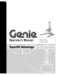
Operator’s Manual Second Edition • Fourth Printing Important Read, understand and obey these safety rules and operating instructions before operating this machine. Only trained and authorized personnel shall be permitted to operate this machine. This manual should be considered a permanent part of your machine and should remain with the machine at all times. If you have any questions, call Genie. Contents Page Safety Rules .............................................................. 1 Controls ..................................................................... 8 Legend ....................................................................... 9 Pre-operation Inspection ........................................... 10 Maintenance ............................................................. 12 Function Tests .......................................................... 15 Workplace Inspection ................................................ 18 Operating Instructions ............................................... 19 Battery Charging Instructions .................................... 21 Transport Instructions ............................................... 22 Tilt-back Operation Instructions ................................ 25 Decals ...................................................................... 28 Specifications ........................................................... 32 Contact us: Copyright © 1996 by Genie Industries First Edition: Internet: http://www.genielift.com e-mail: [email protected] Eighth Printing, October 2001 Second Edition: Fourth Printing, January 2015 "Genie" and "AWP" are registered trademarks of Genie Industries in the U.S.A. and many other countries. "Super Series" is a trademark of Genie Industries. This machine complies with ANSI/SIA 92.3-1990. Printed on recycled paper Printed in U.S.A. Genie AWP Super Series Part No. 82910 Second Edition • Fourth Printing Operator’s Manual Safety Rules Danger Failure to obey the instructions and safety rules in this manual will cause death or serious injury. Do Not Operate Unless: You learn and practice the principles of safe machine operation contained in this operator's manual. 1 Avoid hazardous situations. Know and understand the safety rules before going on to the next section. 2 Always perform a pre-operation inspection. 3 Always perform function tests prior to use. 4 Inspect the workplace. 5 Only use the machine as it was intended. You read, understand and obey the manufacturer's instructions and safety rules— safety and operator's manuals and machine decals You read, understand and obey employer's safety rules and worksite regulations You read, understand and obey all applicable governmental regulations You are properly trained to safely operate the machine. The first time this machine is set up for use, a breather cap is installed. See Pre-operation Inspection section. Part No. 82910 Genie AWP Super Series 1 Operator’s Manual Second Edition • Fourth Printing SAFETY RULES Tip-over Hazards Do not raise the platform unless the base is level, all four outriggers are properly installed and the leveling jacks firmly contact the floor. Do not raise the platform unless the machine is level. Do not set the machine up on a surface where it cannot be leveled using only the leveling jacks. Do not adjust or remove the outriggers while the platform is occupied or raised. Do not move the machine while the platform is raised. Do not cause a horizontal force or side load to the machine by raising or lowering a fixed or overhanging load. Do not push off or pull toward any object outside the platform. Do not place ladders or scaffolds in the platform or against any part of this machine. Maximum allowable force45 lbs / 200 N side Do not place or attach overhanging loads to any part of this machine. Do not transport tools and materials unless they are evenly distributed and can be safely handled by the person in the platform. 2 Genie AWP Super Series Part No. 82910 Second Edition • Fourth Printing Operator’s Manual SAFETY RULES Do not use the machine on a moving or mobile surface or vehicle. ANSI / CSA models: Do not raise the platform when wind speeds may exceed 28 mph / 12.5 m/s. If wind speeds exceed 28 mph / 12.5 m/s when platform is raised, lower the platform and do not continue to operate the machine. Do not operate the machine in strong or gusty winds. Do not increase the surface area of the platform or the load. Increasing the area exposed to the wind will decrease machine stability. CE/AUS standard base models with outdoor outriggers: Do not raise the platform when wind speeds may exceed 28 mph / 12.5 m/s. If wind speeds exceed 28 mph / 12.5 m/s when platform is raised, lower the platform and do not continue to operate the machine. CE/AUS standard base models with indoor outriggers: Indoor use only. Do not raise the platform when wind speeds may exceed 0 mph / 0 m/s. If wind speeds exceed 0 mph / 0 m/s when platform is raised, lower the platform and do not continue to operate the machine. CE/AUS Narrow or RT base models: Indoor use only. Do not raise the platform when wind speeds may exceed 0 mph / 0 m/s. If wind speeds exceed 0 mph / 0 m/s when platform is raised, lower the platform and do not continue to operate the machine. Occupants, equipment and materials shall not exceed the maximum platform capacity. Maximum capacity (all models except Canada) AWP-15S 350 lbs 159 AWP-20S 350 lbs 159 AWP-25S 350 lbs 159 AWP-30S 350 lbs 159 AWP-36S 350 lbs 159 AWP-40S 300 lbs 136 kg kg kg kg kg kg Maximum capacity (models sold in Canada only) AWP-15S 300 lbs 136 AWP-20S 300 lbs 136 AWP-25S 300 lbs 136 AWP-30S 300 lbs 136 AWP-36S 300 lbs 136 AWP-40S 300 lbs 136 kg kg kg kg kg kg Maximum occupancy 1 person Do not operate the machine near drop-offs, holes, bumps, debris, unstable or slippery surfaces or other possible hazardous conditions. Do not alter or disable machine components that in any way affect safety and stability. Part No. 82910 Genie AWP Super Series 3 Operator’s Manual Second Edition • Fourth Printing SAFETY RULES Do not replace items critical to stability with items of different weight or specification. Use only Genie authorized replacement parts. Do not push the Genie AWP from the platform side of the machine. Electrocution Hazards This machine, even with an optional fiberglass platform, is not electrically insulated and will not provide protection from contact with or proximity to electrical current. When moving the machine with a forklift or other transport vehicle, the platform should be fully lowered, the machine should be turned off and no personnel shall remain in the platform. Fall Hazards The guard rail system provides fall protection. If occupants of the platform are required to wear personal fall protection equipment (PFPE) due to job site or employer rules, PFPE equipment and its use shall be in accordance with the PFPE manufacturer’s instructions and applicable governmental requirements. Do not sit, stand or climb on the platform guard rails. Maintain a firm footing on the platform floor at all times. Do not exit the platform while raised. If a power failure occurs, have ground personnel activate the manual lowering valve. Keep away from the machine if it contacts energized power lines or becomes electrically charged. Personnel on the ground or in the platform must not touch or operate the machine until energized power lines are shut off. Maintain safe distances from electrical power lines and apparatus in accordance with applicable governmental regulations and the following chart. Voltage Minimum Safe Approach Distance Phase to Phase Feet 0 to 300V Avoid Contact 300V to 50KV 10 3.05 Keep the platform floor clear of debris. 50KV to 200KV 15 4.60 Lower the platform entry mid-rail or gate before operating. 200KV to 350KV 20 6.10 350KV to 500KV 25 7.62 500KV to 750KV 35 10.67 750KV to 1000KV 45 13.72 4 Genie AWP Super Series Meters Part No. 82910 Second Edition • Fourth Printing Operator’s Manual SAFETY RULES Allow for platform movement, electrical line sway or sag and movement due to strong or gusty winds. Improper Use Hazard Do not use the machine as a ground for welding. Do not leave the machine unattended unless the key is removed to secure from unauthorized use. Do not operate an AC powered machine or a DC battery charger unless using a 3-wire grounded extension cord connected to a grounded AC circuit. Do not alter or disable 3-wire grounded plugs. Collision Hazards Operators must comply with employer, job site and governmental rules regarding the use of personal protective equipment. Check the work area for overhead obstructions or other possible hazards. Bodily Injury Hazard Do not operate the machine with a hydraulic oil or air leak. An air leak or hydraulic leak can penetrate and/or burn skin. Damaged Machine Hazards Do not use a damaged or malfunctioning machine. Be sure all maintenance has been performed as specified in this manual and the Genie AWP Super Series service manual. Be sure all decals are in place and legible. Be sure the operator’s, safety and responsibilities manuals are complete, legible and in the storage container located on the platform. Conduct a thorough pre-operation inspection of the machine and test all functions before each work shift. Immediately tag and remove from service a damaged or malfunctioning machine. Be aware of crushing hazard when grasping the platform guard rail. Do not use the machine as a ground for welding. Do not lower the platform unless the area below is clear of personnel and obstructions. Use common sense and planning to control the movement of the machine on or near inclines. Stay clear of descending platform. Part No. 82910 Genie AWP Super Series 5 Operator’s Manual Second Edition • Fourth Printing SAFETY RULES Battery and Charger Safety - DC Models Electrocution Hazards Connect the charger to a grounded AC circuit only. Burn Hazards Do not expose the battery or charger to water or rain. Batteries contain acid. Always wear protective clothing and eye wear when working with batteries. Before each use, inspect for damage. Replace damaged components before operating. Lifting Hazard Avoid spilling or contacting battery acid. Neutralize battery acid spills with baking soda and water. The battery pack weighs 90 lbs / 40.8 kg. Use the appropriate number of people and proper lifting techniques when lifting the battery pack. The battery pack must remain in an upright position. Explosion Hazards Batteries emit explosive gas. Keep sparks, flames and lighted tobacco away from the battery. Charge the battery in a wellventilated area. Do not disconnect charger DC output wires from the battery when the charger is on. 6 Genie AWP Super Series Part No. 82910 Second Edition • Fourth Printing Operator’s Manual SAFETY RULES Decal Legend Genie product decals use symbols, color coding and signal words to identify the following: Safety alert symbol—used to alert personnel to potential personal injury hazards. Obey all safety messages that follow this symbol to avoid possible injury or death. Red—used to indicate the presence of an imminently hazardous situation which, if not avoided, will result in death or serious injury. Orange—used to indicate the presence of a potentially hazardous situation which, if not avoided, could result in death or serious injury. Yellow with safety alert symbol— used to indicate the presence of a potentially hazardous situation which, if not avoided, may cause minor or moderate injury. Yellow without safety alert symbol—used to indicate the presence of a potentially hazardous situation which, if not avoided, may result in property damage. Green—used to indicate operation or maintenance information. Part No. 82910 Genie AWP Super Series 7 Operator’s Manual Second Edition • Fourth Printing Controls Ground Controls AC and DC Models Ground Controls Air Models Platform Controls 1 Red Emergency Stop button 2 Key switch 3 Outrigger interlock display lights (four) 4 Low battery indicator light for auxiliary lowering 5 DC models: Low battery indicator light 6 Power light 7 Auxiliary platform lowering button 8 Air pressure gauge 9 Control activate button 10 Up/Down switch 8 Genie AWP Super Series Part No. 82910 Second Edition • Fourth Printing Operator’s Manual Legend 1 Lifting eye 2 AC models: Circuit breaker 3 Outrigger storage socket 4 Tilt-back frame retaining pin in strut socket 5 Tilt-back strut 6 Swivel lock 7 Tilt-back frame 8 Loading stop bracket Part No. 82910 9 Loading pivot bar 10 Forklift pocket 11 Airline lubricator adjustment knob 12 Air supply for machine 13 Airline lubricator 14 DC models: Battery pack with charger 15 Hydraulic power unit 16 Winching/tie-down point 17 Bubble level 18 Base 19 Sliding T-handle 20 AC outlet 21 Platform controls 22 Operator's manual storage container 23 Manual lowering valve (under machine) 24 Base outrigger socket Genie AWP Super Series 25 Outrigger with leveling jack 26 Outrigger lock pin 27 Platform 28 Platform entry midrail or gate 29 AC models: Power supply for machine DC models: Power to platform 30 Ground controls 31 Mast 9 Operator’s Manual Second Edition • Fourth Printing Pre-operation Inspection Fundamentals It is the responsibility of the operator to perform a pre-operation inspection and routine maintenance. The pre-operation inspection is a visual inspection performed by the operator prior to each work shift. The inspection is designed to discover if anything is apparently wrong with a machine before the operator performs the function tests. Do Not Operate Unless: You learn and practice the principles of safe machine operation contained in this operator’s manual. 1 Avoid hazardous situations. 2 Always perform a pre-operation inspection. The pre-operation inspection also serves to determine if routine maintenance procedures are required. Only routine maintenance items specified in this manual may be performed by the operator. Refer to the list on the next page and check each of the items. Know and understand the pre-operation inspection before going on to the next section. 3 Always perform the function tests prior to use. 4 Inspect the workplace. 5 Only use the machine as it was intended. Breather Cap - AC & DC Models Component damage will occur if the machine is operated without a breather cap. Check to make sure the breather cap is in place in the hydraulic reservoir. If damage or any unauthorized variation from factory delivered condition is discovered, the machine must be tagged and removed from service. Repairs to the machine may only be made by a qualified service technician, according to the manufacturer's specifications. After repairs are completed, the operator must perform a pre-operation inspection again before going on to the function tests. Scheduled maintenance inspections shall be performed by qualified service technicians, according to the manufacturer's specifications and the requirements listed in the responsibilities manual. AWP-36 & AWP-40: The first time these machines are set up for use, the pipe plug in the hydraulic reservoir should be removed and permanently replaced with a breather cap. A breather cap is supplied and can be found in an envelope taped to the mast near the platform controls. 10 Genie AWP Super Series Part No. 82910 Second Edition • Fourth Printing Operator’s Manual PRE-OPERATION INSPECTION Pre-operation Inspection Be sure that the operator’s, safety and responsibilities manuals are complete, legible and in the storage container located on the platform. Sequencing cables and pulleys Be sure that all decals are legible and in place. See Decals section. Mast columns and counterweight Check for battery fluid leaks and proper fluid level. Add distilled water if needed. See Maintenance section. Outriggers, leveling jacks and footpads AC & DC models: Check for hydraulic oil leaks and proper oil level. Add oil if needed. See Maintenance section. RT base models: Check for proper tire pressure. Add air to tires if needed. See Maintenance section. Air models: Check the oil level of the airline lubricator. See Maintenance section. Air models: Check the oil lubricator canister drip rate. Adjust as needed. See Maintenance section. Lifting chains and idler wheels Nuts, bolts and other fasteners Breather cap Adjustable glide pads Check entire machine for: Dents or damage Corrosion or oxidation Cracks in welds or structural components Inspect and clean battery terminals and all battery cable connections. Be sure that all structural and other critical components are present and all associated fasteners and pins are in place and properly tightened. Air models: Check the air filter/regulator canister. Drain water as needed. See Maintenance section. Check the following components or areas for damage, improperly installed or missing parts and unauthorized modifications: Electrical components, wiring and electrical cables AC & DC models: Hydraulic power unit, hoses, fittings and cylinder Air models: Air power unit, airlines, fittings and cylinder Platform entry mid-rail or gate Part No. 82910 Genie AWP Super Series 11 Operator’s Manual Second Edition • Fourth Printing Maintenance Check the Battery - DC Models Proper battery condition is essential to good machine performance and safe operation. Improper fluid levels or damaged cables and connections can result in component damage and hazardous conditions. Observe and Obey: Electrocution hazard. Contact with hot or live circuits could result in death or serious injury. Remove all rings, watches and other jewelry. Only routine maintenance items specified in this manual shall be performed by the operator. Scheduled maintenance inspections shall be completed by qualified service technicians, according to the manufacturer's specifications and the requirements specified in the responsibilities manual. Bodily injury hazard. Batteries contain acid. Avoid spilling or contacting battery acid. Neutralize battery acid spills with baking soda and water. Perform this test after fully charging the battery. Maintenance Symbols Legend The following symbols have been used in this manual to help communicate the intent of the instructions. When one or more of the symbols appear at the beginning of a maintenance procedure, it conveys the meaning below. 1 Put on protective clothing and eye wear. 2 Remove the battery vent caps. 3 Check the battery acid level. If needed, replenish with distilled water to the bottom of the battery fill tube. Do not overfill. 4 Install the vent caps. Indicates that tools will be required to perform this procedure. Indicates that new parts will be required to perform this procedure. 12 Genie AWP Super Series Part No. 82910 Second Edition • Fourth Printing Operator’s Manual MAINTENANCE Check the Hydraulic Oil Level Maintaining the hydraulic oil at the proper level is essential to machine operation. Improper hydraulic oil levels can damage hydraulic components. Daily checks allow the inspector to identify changes in oil level that might indicate the presence of hydraulic system problems. 1 Be sure the platform is fully lowered. 2 Check the sight gauge on the side of the hydraulic reservoir. Result: The hydraulic oil level should be visible in the middle of the sight gauge. Do not overfill. Hydraulic oil specifications Hydraulic oil type Chevron Rykon Premium MV equivalent Check the Air Line Lubricator Oil Level - Air Models Maintaining the proper oil level in the lubricator canister is essential to safe operation and good machine performance. Failure to keep the lubricator canister at the proper oil level could result in unsafe operating conditions and possible component damage. 1 Be sure the platform is fully lowered. 2 Inspect the lubricator canister for the proper oil level. Result: The oil level must be within 1/2 inch / 12.7 mm from the top of the lubricator canister. 3 To add oil, remove the oil lubricator canister from the lubricator base and fill with oil. Install the canister back onto the lubricator base. Oil Specifications Oil Type 10W automotive engine oil Check the Tire Pressure - RT Base Models It is essential to maintain proper pressure in all airfilled tires. Improperly inflated tires can affect machine handling. 1 Check each tire with an air pressure gauge. Add air as needed. The proper air pressure is stamped on the tire. Part No. 82910 Genie AWP Super Series 13 Operator’s Manual Second Edition • Fourth Printing MAINTENANCE Check the Oil Lubricator Canister Drip Rate - Air Models Maintaining the proper oil drip rate into the lubricator canister is essential to safe operation and good machine performance. Failure to maintain the proper drip rate could result in machine component damage. Scheduled Maintenance Maintenance performed quarterly, annually and every two years must be completed by a person trained and qualified to perform maintenance on this machine according to the procedures found in the service manual for this machine. Machines that have been out of service for more than three months must receive the quarterly inspection before they are put back into service. 1 While raising the platform, visually inspect the oil lubricator sight gauge. Result: There should be a maximum of 1 to 2 drops of oil visible in the sight gauge. 2 To adjust the drip rate, turn the oil flow control valve clockwise to decrease the flow or counterclockwise to increase the flow. 3 Repeat this procedure until the proper oil drip rate is achieved. Check the Air Filter/Regulator Canister - Air Models It is essential to drain the air filter/regulator canister of water to ensure good air motor performance and service life. A water-filled canister could cause the air motor to perform poorly and continued use could cause component damage. 1 Check the air filter/regulator canister for any water accumulation. 2 If water is visible, loosen the drain plug at the bottom of the canister and allow the water to drain out. 3 Tighten the drain plug. 14 Genie AWP Super Series Part No. 82910 Second Edition • Fourth Printing Operator’s Manual Function Tests Fundamentals The function tests are designed to discover any malfunctions before the machine is put into service. The operator must follow the step-by-step instructions to test all machine functions. Do Not Operate Unless: You learn and practice the principles of safe machine operation contained in this operator’s manual. 1 Avoid hazardous situations. 2 Always perform a pre-operation inspection. A malfunctioning machine must never be used. If malfunctions are discovered, the machine must be tagged and removed from service. Repairs to the machine may only be made by a qualified service technician, according to the manufacturers specifications. After repairs are completed, the operator must perform a pre-operation inspection and function tests before putting the machine into service. 3 Always perform the function tests prior to use. Know and understand the function tests before going on to the next section. 4 Inspect the workplace. 5 Only use the machine as it was intended. Part No. 82910 Genie AWP Super Series 15 Operator’s Manual Second Edition • Fourth Printing FUNCTION TESTS Function Tests 8 Repeat this procedure for each of the remaining outriggers. Setup 9 Use the bubble level and adjust the leveling jacks until the machine base is level. 1 Position the machine on a firm surface directly below the desired work area. Test Emergency Stop 2 Connect to the appropriate power source: DC models: Connect the battery pack. AC models: Connect to a grounded 15A AC power supply. Use a 12 gauge / 3.3mm2 3-wire grounded extension cord no longer than 50 feet / 13 m. Air models: Connect the air line. 3 Insert the key and turn to platform control. 4 Pull out the red Emergency Stop button to the on position at the ground controls. 5 Twist to release the red Emergency Stop button at the platform controls. 10 Push in the red Emergency Stop button at the ground controls to the off position. 11 Push in the control activate button and rotate the up/down switch in the direction of intended travel. ANSI & CSA CE Result: AC & DC models: The power light should come on. Air models: The air pressure gauge should read 80-110 psi /5.5 - 7.8 bar. 6 Select an outrigger and slide it into a base socket until the outrigger lock pin snaps into place. Adjust the outrigger to level the machine and raise the base casters slightly off the ground. Level the machine using only the outriggers. a b a a b b control activate button up/down switch Result: The up/down function should not operate. 7 Check the interlock display lights at the ground controls. Confirm that the corresponding light is on. 16 Genie AWP Super Series Part No. 82910 Second Edition • Fourth Printing Operator’s Manual FUNCTION TESTS 12 Push in the red Emergency Stop button at the platform controls to the off position. 13 Pull out the red Emergency Stop button at the ground controls to the on position. 14 Push in the control activate button and rotate the up/down switch in the direction of intended travel. Result: The up/down function should not operate. Test Outrigger Interlock 23 Connect the power source to the machine. 24 Turn the key switch to platform control. 25 Raise the platform slightly. 26 Disconnect the power source from the machine. 27 Push in the control activate button and rotate the up/down switch in the down direction. Result: The platform should lower. 28 Connect the power source to the machine. Test Manual Lowering 15 Twist to release the red Emergency Stop button at the platform controls. Result: The up/down functions should operate. 16 Unscrew one leveling jack until the corresponding interlock display light turns off. Result: The up/down function should not operate. 17 Return the leveling jack to the previous setting and check the bubble level. 29 Raise the platform slightly. 30 Activate the manual lowering valve located at the bottom of the hydraulic cylinder. Result: The platform should lower. 18 Repeat this procedure for each outrigger. Test Auxiliary Platform Lowering - AC & DC Models 19 Raise the platform slightly. 20 Disconnect the power source from the machine. 21 Turn the key switch to ground control. 22 Push in the auxiliary platform lowering button at the ground controls. Result: The platform should lower. Part No. 82910 Genie AWP Super Series 17 Operator’s Manual Second Edition • Fourth Printing Workplace Inspection Workplace Inspection Be aware of and avoid the following hazardous situations: Do Not Operate Unless: You learn and practice the principles of safe machine operation contained in this operator’s manual. · drop-offs or holes · bumps, floor obstructions or debris · slopes that exceed the machine’s leveling capability · unstable or slippery surfaces · overhead obstructions and high voltage conductors · hazardous locations · inadequate surface support to withstand all load forces imposed by the machine · wind and weather conditions · the presence of unauthorized personnel · other possible unsafe conditions 1 Avoid hazardous situations. 2 Always perform a pre-operation inspection. 3 Always perform function tests prior to use. 4 Inspect the workplace. Know and understand the work place inspection before going on to the next section. 5 Only use the machine as it was intended. Fundamentals The workplace inspection helps the operator determine if the workplace is suitable for safe machine operation. It should be performed by the operator prior to moving the machine to the workplace. It is the operator’s responsibility to read and remember the workplace hazards, then watch for and avoid them while moving, setting up and operating the machine. 18 Genie AWP Super Series Part No. 82910 Second Edition • Fourth Printing Operator’s Manual Operating Instructions Setup 1 Position the machine on a firm surface directly below the desired work area. You learn and practice the principles of safe machine operation contained in this operator’s manual. 2 Connect to the appropriate power source: DC models: Connect the battery pack. AC models: Connect to a grounded 15A AC power supply. Use a 12 gauge / 3.3mm2 3-wire grounded extension cord no longer than 50 feet / 13 m. Air models: Connect the airline. 1 Avoid hazardous situations. 3 Insert the key and turn to platform control. 2 Always perform a pre-operation inspection. 4 Pull out the red Emergency Stop button at the ground controls and twist to release the red Emergency Stop at the platform controls. Be sure the power light is on or the air pressure gauge reads 80-110 psi / 5.5 - 7.8 bar. Do Not Operate Unless: 3 Always perform function tests prior to use. 4 Inspect the workplace. 5 Only use the machine as it was intended. 5 Install the outriggers and adjust to level the machine and raise the base casters slightly off the ground. Fundamentals The Operating Instructions section provides instructions for each aspect of machine operation. It is the operator's responsibility to follow all the safety rules and instructions in the operator's, safety and responsibilities manuals. Using the machine for anything other than lifting personnel, along with their tools and materials, to an aerial work site is unsafe and dangerous. If more than one operator is expected to use a machine at different times in the same work shift, each operator is expected to follow all safety rules and instructions in the operator’s manual. That means every new operator should perform a preoperation inspection, function tests and a work place inspection before using the machine. Part No. 82910 6 Be sure all four interlock display lights at the ground controls are on and all four outriggers are in firm contact with the ground. 7 Use the bubble level to make sure the machine is level. Note: If adjustment is necessary, check the bubble level and interlock display again to make sure the machine is level and all four interlock display lights are on. Genie AWP Super Series 19 Operator’s Manual Second Edition • Fourth Printing OPERATING INSTRUCTIONS Emergency Stop Push in the red Emergency Stop button at the platform controls or at the ground controls to stop the up function. Platform Raise and Lower 1 Pull out the red Emergency Stop button to the on position at the ground controls. Twist to release the red Emergency Stop button at the platform controls. 2 Push in the control activate button and rotate the up/down switch in the desired direction of travel. Manual Lowering 1 Activate the manual lowering valve located at the bottom of the hydraulic cylinder. Auxiliary Platform Lowering - AC & DC Models 1 Turn the key switch to ground control. Pull out the red Emergency Stop button to the on position. 2 Activate the auxiliary platform lowering button at the ground controls. Fall Protection Personal fall protection equipment (PFPE) is not required when operating this machine. If PFPE is required by job site or employer rules, the following shall apply: All PFPE must comply with applicable governmental regulations and must be inspected and used in accordance with the manufacturer’s instructions. After Each Use 1 Select a safe storage location—firm, level surface, weather protected, clear of obstruction and traffic. 2 Chock the wheels to prevent the machine from rolling. 3 Remove the key to secure from unauthorized use. 4 DC models: Recharge the battery. 20 Genie AWP Super Series Part No. 82910 Second Edition • Fourth Printing Operator’s Manual OPERATING INSTRUCTIONS To Charge Battery 1 Open the battery pack lid to access the battery. 2 Remove the battery vent caps and check the battery acid level. If necessary, add only enough distilled water to cover the plates. Do not overfill prior to the charge cycle. Battery and Charger Instructions 3 Replace the battery vent caps. 4 Be sure that the DC output cord is properly connected to the battery. Black to negative, red to positive. Observe and Obey: Do not use an external charger or booster battery. Charge the battery in a well-ventilated area. Use proper AC input voltage for charging as indicated on the charger. Use only Genie authorized battery and charger. 5 Connect the battery charger to a grounded AC circuit. 6 The charger will turn off automatically when the battery is fully charged. 7 Check the battery acid level when the charge cycle is complete. Replenish with distilled water to the bottom of the fill tube. Do not overfill. Dry Battery Filling and Charging Instructions 1 Remove the battery vent caps and permanently remove the plastic seal from the battery vent openings. 2 Fill each cell with battery acid (electrolyte) until the level is sufficient to cover the plates. Do not fill to maximum level until the battery charge cycle is complete. Overfilling can cause the battery acid to overflow during charging. Neutralize battery acid spills with baking soda and water. 3 Install the battery vent caps. 4 Charge the battery. 5 Check the battery acid level when the charging cycle is complete. Replenish with distilled water to the bottom of the fill tube. Do not overfill. Part No. 82910 Genie AWP Super Series 21 Operator’s Manual Second Edition • Fourth Printing OPERATING INSTRUCTIONS Lifting Instructions The number of people required to load and unload a machine is dependent on a number of factors, including but not limited to: · the physical condition, strength and disabilities or prior injuries of the people involved Transport Instructions Observe and Obey: Be sure the transport vehicle capacity and loading surfaces are sufficient to support the machine weight. See the serial plate for the machine weight. Some pick-up truck tailgates are not strong enough to support the weight of the machine and may require reinforcement. Do not load the machine onto a transport vehicle unless it is parked on a level surface. The transport vehicle must be secured to prevent rolling while the machine is being loaded. The machine must be securely fastened to the transport vehicle. Use chains or straps of ample load capacity. · the vertical and horizontal distances the machine has to be moved · the number of times the machine will be loaded or unloaded · the stance, posture and grip used by the people involved · the lifting techniques used · the site conditions and weather in which the activity is being performed (i.e., slippery, icy, raining) The appropriate number of people and proper lifting techniques must be used to prevent physical injury. Be sure to lock both swivel casters on the tilt-back frame. Do not transport with the machine resting on the tilt-back frame. 22 Genie AWP Super Series Part No. 82910 Second Edition • Fourth Printing Operator’s Manual OPERATING INSTRUCTIONS Loading for Transport 1 Fully lower the platform. 2 Push in the red Emergency Stop buttons, turn the key switch to the off position and remove the key. 3 Remove the outriggers from the base and place them in the storage sockets. 8 Position the machine flush against the loading surface. Lower and lock the stop bracket to the lowest lock pin position above the loading surface. 9 All models with tilt-back frame: 4 DC models: Disconnect the battery cable and remove the battery pack. Be sure both stop bracket lock pins are fully locked. 5 Inspect the entire machine for loose or unsecured items. Be sure both tilt-back frame swivel casters are locked. 6 Slide the stop bracket to the top lock position. a b a b stop bracket loading pivot All models without tilt-back frame a b a b 10 Slide out the T-handle until the lock pin snaps into place. 11 Lift the T-handle to tilt the machine onto the loading surface. Use the appropriate number of people and proper lifting techniques. 12 Carefully push the machine into the transport position. 13 Return the sliding T-handle to the stowed position. 14 Secure the machine base and mast to the transport vehicle. See Securing the Machine on the next page. stop bracket loading pivot 15 Reverse this procedure to unload the machine. All models with tilt-back frame 7 Hook the loading pivot to the stop bracket. Part No. 82910 Genie AWP Super Series 23 Operator’s Manual Second Edition • Fourth Printing OPERATING INSTRUCTIONS Securing the Machine Use chains or straps of ample load capacity. Winching the Machine onto a Flatbed Truck Use a minimum of 2 chains. 1 Fully lower the platform. Adjust the rigging to prevent damage to the chains. 2 Push in the red Emergency Stop buttons, turn the key switch to the off position and remove the key. 3 Remove the outriggers from the base and place them in the storage sockets. 4 Inspect the entire machine for loose or unsecured items. 5 Connect the cable to the winching point located at the rear of the base. 6 Carefully winch the machine onto the truck. 7 Secure the machine base to the transport vehicle. See Securing the Machine. Loading the Machine With a Crane Use the lifting eye mounted on the rear mast column. The battery pack must be removed before lifting the machine with a crane. Disconnect the battery plug before removing the battery pack. Be sure to inspect the machine and remove any loose or unsecured items. Always place the lifting hook through the lifting eye so that it points away from the machine. 24 Genie AWP Super Series Part No. 82910 Second Edition • Fourth Printing Operator’s Manual OPERATING INSTRUCTIONS Lifting Instructions The number of people required to load and unload a machine is dependent on a number of factors, including but not limited to: Tilt-back Operation Instructions Observe and obey: The retaining pin must be inserted to prevent the spring-loaded tilt-back frame from dropping. Do not tilt the machine back unless the area is clear of personnel and obstructions. Do not stand behind or under the tilt-back frame when raising or lowering it. · the physical condition, strength and disabilities or prior injuries of the people involved · the vertical and horizontal distances the machine has to be moved · the number of times the machine will be loaded or unloaded · the stance, posture and grip used by the people involved · the lifting techniques used · the site conditions and weather in which the activity is being performed (i.e., slippery, icy, raining) Tilt-back Frame The appropriate number of people and proper lifting techniques must be used to prevent physical injury. The Genie AWP Super Series has a tilt-back frame which allows the machine to roll through a standard doorway. The tilt-back frame is standard equipment on standard base AWP-36S and 40S models, and optional on standard base AWP-15S, 20S, 25S and 30S models. The tilt-back frame is not available on narrow base machines or rough terrain base machines. Part No. 82910 Genie AWP Super Series 25 Operator’s Manual Second Edition • Fourth Printing OPERATING INSTRUCTIONS Lowering the Tilt-back Assembly Tilting Back the Machine 1 Be sure the area behind the machine and under the tilt-back frame is clear of personnel and obstructions. 2 Fully lower the platform. 3 Remove the outriggers from the base and place them in the storage sockets. The tilt-back frame is spring loaded and will immediately fall outward when the retaining pin is removed. Maintain a firm grasp on the tiltback frame and remove the retaining pin. 4 Lower the tilt-back frame and guide the tilt-back strut into the strut socket. 1 Slide out the Thandle until the lock pin snaps into place. 2 Lift the machine with the T-handle to mid-tilt position— casters on the tilt-back frame are in contact with the floor, and the machine is supported by the extended tilt-back strut. Use the appropriate number of people and proper lifting techniques. 3 Continue lifting until the telescoping tilt-back strut is completely compressed. 4 Return the sliding T-handle to the stowed position. 5 Insert the retaining pin into the strut socket. 26 Genie AWP Super Series Part No. 82910 Second Edition • Fourth Printing Operator’s Manual OPERATING INSTRUCTIONS Returning the Machine to Standing Position Stowing the Tilt-back Assembly 1 Remove the retaining pin. 1 Be sure the area below the machine base and T-handle is clear of personnel and obstructions. 2 Slide out the T-handle untl the lock pin snaps into place. 3 Carefully pull down the T-handle until the machine rests at midtilt position. 4 Lower the machine with the T-handle until the base casters are in contact with the ground. Use the appropriate number of people and proper lifting techniques. 5 Return the sliding T-handle to the stowed position. Part No. 82910 2 Firmly grasp the tilt-back frame and remove the tilt-back strut from the strut socket. 3 Lift the tilt-back frame, hold in an upright position against the spring and secure with the retaining pin. Genie AWP Super Series 27 Operator’s Manual Second Edition • Fourth Printing Decals Inspection for Decals with Words Determine whether the decals on your machine have words or symbols. Use the appropriate inspection to verify that all decals are legible and in place. Part No. Description Quantity Part No. Description Quantity 27838 Warning - Tilt-back Hazards/Instructions 1 37145 Label - Manual Lowering Valve 1 27839 Label - Sliding T-handle 1 38122 Label - Manual Storage Container 1 27840 Label - Retaining Pin 1 38142 Label - Circuit Breaker, AC models 1 27841 Label - Stop Bracket 1 41266 Label - Interlock Display, Air Models 1 27842 Label - Loading Pivot 1 41268 Label - Interlock Display, Air Models 1 27843 Label - Tilt-back Strut 1 52996 Cosmetic - Genie Logo 1 27844 Label - Strut Socket 1 52998 Cosmetic - AWP-15S 2 27857 Caution - Pipe Plug 1 52999 Cosmetic - AWP-20S 2 27863 Warning - Collision Hazard 3 62992 Cosmetic - AWP-25S 2 27864 Notice - Lower Stop Bracket Before . . . 1 62993 Cosmetic - AWP-30S 2 27865 Label - Bubble Level 1 62994 Cosmetic - AWP-36S 2 27867 Label - Swivel Lock 1 62995 Cosmetic - AWP-40S 2 27868 Danger - Relief Valve 1 72086 Label - Lifting Eye 1 27872 Danger - Tip-over Hazard, Outriggers 1 72843 Danger - General Safety 1 27873 Notice - Maintain Firm Grasp 1 82366 Label - Chevron Rykon 1 27874 Label - Insert Retaining Pin 1 82780 Label - Interlock Display 1 28174 Label - Power to Platform, 230V 2 82781 Label - Interlock Display 1 28235 Label - Power to Platform, 115V 2 82802 Label - Function Enable 1 28372 Caution - Quick Disconnect 1 82907 Danger - Battery Charger Safety 1 31070 Danger - Tip-over Hazard, Moving 1 82975 Danger - Collision Hazard 1 31071 Warning - Failure to Read 1 82986 Danger - Electrocution Hazard 1 31245 Warning - Collision Hazard 1 97519 Notice - Side Force, ANSI 1 37141 Notice - Manual Lowering Instructions 1 97522 Label - Wheel Load 4 37142 Notice - Operating Instructions 1 97523 Label - Outrigger Load 4 37143 Notice - Max Capacity 300 lbs / 136 kg 1 37144 Notice - Max Capacity 350 lbs / 159 kg 1 28 Genie AWP Super Series Part No. 82910 Second Edition • Fourth Printing Operator’s Manual DECALS Note: Platform decals may be in diffferent locations on optional fiberglass basket. Models with Tilt-back Frame Part No. 82910 Models without Tilt-back Frame Genie AWP Super Series 29 Operator’s Manual Second Edition • Fourth Printing DECALS Inspection for Decals with Symbols Determine whether the decals on your machine have words or symbols. Use the appropriate inspection to verify that all decals are legible and in place. Part No. Description Quantity Part No. Description Quantity 28174 Label - Power to Platform, 230V 2 82976 Danger - Wind Speed, 51 cm Outrigger 4 28235 Label - Power to Platform, 115V 2 82977 Danger - Wind Speed, 66 cm Outrigger 4 52996 Cosmetic - Genie Logo 1 82978 Danger - Wind Speed, 77 cm Outrigger 4 52998 Cosmetic - AWP-15S 2 82979 Danger - Wind Speed, 91 cm Outrigger 4 52999 Cosmetic - AWP-20S 2 82980 Danger - Wind Speed, 1.02 m Outrigger 4 62992 Cosmetic - AWP-25S 2 82984 Danger - Wind Speed, 2.16 m Outrigger 4 62993 Cosmetic - AWP-30S 2 82987 Danger - Electrocution Hazard 1 62994 Cosmetic - AWP-36S 2 82988 Label - Read the Manual, Tilt-back Frame 1 62995 Cosmetic - AWP-40S 2 97522 Label - Wheel Load 4 82481 Danger - Battery Charger Safety 1 97523 Label - Outrigger Load 4 82487 Label - Read the Manual 1 1257853 Danger - Wind Speed, 1.91 m Outrigger 4 82614 Caution - Collision Hazard 1 1257854 Danger - Wind Speed, 1.52 m Outrigger 4 82780 Label - Interlock Display 1 1260610 Danger - Wind Speed, 1.17 m Outrigger 4 82781 Label - Interlock Display 1 82802 Label - Function Enable 1 82913 Danger - Max Capacity, 159 kg 1 82914 Danger - Max Capacity, 136 kg 1 82915 Label - Manual Lowering Valve 1 82916 Danger - Maximum Manual Force 1 82973 Warning - Insert Pin 1 82974 Warning - Collision Hazard 1 30 Genie AWP Super Series Part No. 82910 Second Edition • Fourth Printing Operator’s Manual DECALS Note: Platform decals may be in diffferent locations on optional fiberglass basket. 82916 * 82976 or 82977 or 82978 or 82979 or 82980 or 82981 or 82984 or 1257853 or 1257854 or 1260610 Part No. 82910 Genie AWP Super Series 31 Operator’s Manual Second Edition • Fourth Printing Specifications Machine Specifications Standard Base Specifications Height, working maximum AWP-15S AWP-20S AWP-25S AWP-30S AWP-36S AWP-40S 21 ft 4 in 26 ft 1 in 30 ft 9 in 35 ft 6 in 42 ft 5 in 46 ft 3 in 6.5 m 8.0 m 9.4 m 10.8 m 12.9 m 14.1 m Height, platform maximum AWP-15S AWP-20S AWP-25S AWP-30S AWP-36S AWP-40S 15 ft 4 in 20 ft 1 in 24 ft 9 in 29 ft 6 in 36 ft 6 in 40 ft 3 in 4.7 m 6.1 m 7.6 m 9.0 m 11.1 m 12.3 m Machine weight (DC / AC models) AWP-15S 718 / 628 AWP-20S 767 / 677 AWP-25S 817 / 727 AWP-30S 867 / 777 AWP-36S 1107 / 1017 AWP-40S 1130 / 1040 Height, stowed AWP-15S, 20S, 25S, 30S AWP-36S, 40S 78 in 1091/2 in Width 350 lbs 159 kg Length AWP-15S, 20S, 25S, 30S AWP-36S, 40S Lift capacity - AWP-40S models except Canada 300 lbs 136 kg Platform dimensions - all models (length x width x height) Lift capacity models sold in Canada only 300 lbs 136 kg Ambient operating temperature -20°F to 135°F -29°C to 57°C 326 348 371 393 502 513 / / / / / / 285 307 330 352 461 472 kg kg kg kg kg kg 2.0 m 2.8 m 29 in 73.6 cm Lift capacity - AWP-15S, 20S, 25S, 30S & 36S models except Canada Power source DC model 12V AC model 110V or 220V Air motor 100 psi / 6.9 bar @ 80 cfm / 37760 cc/sec lbs lbs lbs lbs lbs lbs 46 in 55 in 1.2 m 1.4 m Standard platform gated or sliding mid-rail 27 x 26 x 443/4 in 69 cm x 66 cm x 1.1 m Gated ultra-narrow platform 22 x 18 x 443/4 in 56 cm x 46 cm x 1.1 m Gated narrow platform 26 x 20 x 443/4 in 66 cm x 51 cm x 1.1 m Standard fiberglass platform 29 x 261/2 x 431/2 in 74 cm x 67 cm x 1.1 m Narrow fiberglass platform 26 x 22 x 431/2 in 66 cm x 56 cm x 1.1 m Airborne noise emissions 80 dB Maximum sound level at normal operating workstations (A-weighted) Front entry gated narrow platform Wheel load, maximum 509 lbs 231 kg Extra large front and side entry 30 x 28 x 443/4 in platform 76 cm x 71 cm x 1.1 m Outrigger load, maximum 400 lbs 181 kg 32 20 x 26 x 443/4 in 51cm x 66 cm x 1.1 m Continuous improvement of our products is a Genie policy. Product specifications are subject to change without notice or obligation. Genie AWP Super Series Part No. 82910 Second Edition • Fourth Printing Operator’s Manual SPECIFICATIONS Standard Base Specifications Outrigger footprint (l x w) ANSI Outrigger footprint (l x w) CSA Outrigger footprint (l x w) CE Indoor AWP-15S 603/4 x 523/4 in 1.5 x 1.3 m 603/4 x 523/4 in 1.5 x 1.3 m 603/4 x 523/4 in 1.5 x 1.3 m AWP-20S 603/4 x 523/4 in 1.5 x 1.3 m 691/4 x 611/4 in 1.8 x 1.6 m 603/4 x 523/4 in 1.5 x 1.3 m AWP-25S 603/4 x 523/4 in 1.5 x 1.3 m 831/2 x 751/2 in 2.1 x 1.9 m 691/4 x 611/4 in 1.8 x 1.6 m 691/4 x 611/4 in 1.8 x 1.6 m 153/4 / 8 in 39.7 / 20.3 cm 153/4 / 8 in 39.7 / 20.3 cm 153/4 / 8 in 39.7 / 20.3 cm 211/2 / 121/4 in 54.6 / 30.8 cm AWP-30S 1 69 /4 x 611/4 in 1.8 x 1.6 m 1 97 /2 x 891/2 in 2.5 x 2.3 m 751/2 x 671/2 in 1.9 x 1.7 m 1171/4 x 1091/2 in 3.0 x 2.8 m 181/2 / 43/4 in 46.6 / 11.9 cm 37 / 183/4 in 94.1 / 47.8 cm 221/4 / 8 in 56.5 / 20.3 cm 831/4 x 751/4 in 2.1 x 1.9 m 141/2 / 51/2 in 36.9 / 7.4 cm 201/4 / 93/4 in 51.2 / 24.5 cm 141/2 / 51/2 in 36.9 / 7.4 cm 30 / 163/4 in 76 / 42.4 cm AWP-36S 1 83 /4 x 751/4 in 2.1 x 1.9 m 1 117 /4 x 1091/4 in 3.0 x 2.8 m 831/4 x 751/4 in 2.1 x 1.9 m 139 x 131 in 3.5 x 3.3 m 281/2 / 141/4 in 72.7 / 36.2 cm 52 / 311/4 in 1.3 m / 79.3 cm 281/2 / 141/4 in 72.7 / 36.2 cm 89 x 81 in 2.3 x 2.1 m 14 / 3 in 35.1 / 7.4 cm 283/4 / 141/4 in 72.6 / 36.2 cm 191/4 / 71/4 in 48.6 / 18.2 cm 321/2 / 17 in 82.5 / 43.4 cm AWP-40S 89 x 81 in 2.3 x 2.0 m 1171/4 x 1091/4 in 3.0 x 2.8 m 89 x 81 in 2.3 x 2.0 m 153 x 145 in 3.9 x 3.7 m 311/4 / 141/2 in 79.4 / 37.1 cm 503/4 / 283/4 in 1.3 m / 73 cm 311/4 / 141/2 in 79.4 / 37.1 cm Corner access/wall access* 503/4 / 283/4 in 52 / 311/4 in CE Outdoor 1.3 m / 73 cm 1.3 m / 79.3 cm * Corner of platform top rail to corner of wall with ability to rotate leveling jack. 503/4 / 283/4 in 1.3 m / 73 cm Outrigger footprint (l x w) CE Outdoor Corner access/wall ANSI Corner access/wall CSA Corner access/wall CE Indoor Corner access/wall CE Outdoor access* access* access* access* Outrigger footprint (l x w) ANSI Outrigger footprint (l x w) CSA Outrigger footprint (l x w) CE Indoor Outrigger footprint (l x w) CE Outdoor Corner access/wall access* ANSI Corner access/wall access* CSA Corner access/wall access* CE Indoor Part No. 82910 Genie AWP Super Series 33 Operator’s Manual Second Edition • Fourth Printing SPECIFICATIONS Machine Specifications Narrow Base Specifications Height, working maximum AWP-15S AWP-20S AWP-25S AWP-30S 21 ft 4 in 26 ft 1 in 30 ft 9 in 35 ft 6 in 6.5 m 8.0 m 9.4 m 10.8 m Height, platform maximum AWP-15S AWP-20S AWP-25S AWP-30S 15 ft 4 in 20 ft 1 in 24 ft 9 in 29 ft 6 in 4.7 m 6.1 m 7.6 m 9.0 m Lift capacity - AWP-15S, 20S, 25S & 30S models except Canada 350 lbs 159 kg Lift capacity models sold in Canada only 300 lbs 136 kg Power source DC model 12V AC model 110V or 220V Air motor 100 psi / 6.9 bar @ 80 cfm / 37760 cc/sec Ambient Operating Temperature -20°F to 135°F -29°C to 57°C Machine weight (DC / AC models) AWP-15S 711 / 621 AWP-20S 750 / 660 AWP-25S 784 / 694 AWP-30S 819 / 729 lbs lbs lbs lbs 323 / 282kg 340 / 299kg 356 / 315 kg 371 / 330 kg Height, stowed 78 in 2.0 m Width 22 in 55.8 cm 491/2 in 1.3 m Length Platform dimensions Gated ultra-narrow platform (l x w x h) 22 x 18 x 443/4 in 56 cm x 46 cm x 1.1 m Gated narrow platform (l x w x h) 26 x 20 x 443/4 in 66 cm x 51 cm x 1.1 m Narrow fiberglass platform (l x w x h) 26 x 22 x 431/2 in 66 cm x 56 cm x 1.1 m Wheel load, maximum 509 lbs 231 kg Outrigger load, maximum 400 lbs 181 kg Airborne noise emissions 80 dB Maximum sound level at normal operating workstations (A-weighted) Outrigger Specifications Narrow Base AWP-15S AWP-20S AWP-25S AWP-30S Outrigger footprint (l x w) ANSI 64 x 481/4 in 1.6 x 1.2 m 64 x 481/4 in 1.6 x 1.2 m 64 x 481/4 in 1.6 x 1.2 m 711/2 x 58 in 1.8 x 1.5 m Outrigger footprint (l x w) CSA 711/2 x 58 in 1.8 x 1.5 m 741/2 x 651/2 in 1.9 x 1.6 m 831/4 x 74 in 2.1 x 1.9 m 951/4 x 893/4 in 2.4 x 2.3 m Outrigger footprint (l x w) CE Indoor 64 x 481/4 in 1.6 x 1.2 m 711/4 x 58 in 1.8 x 1.5 m 711/4 x 58 in 1.8 x 1.5 m 741/2 x 651/2 in 1.9 x 1.6 m CE/AUS Narrow Base or Rough Terrain base machines are Indoor Use Only, even with longer outriggers. Corner access/wall access* 16 / 11 in ANSI 40.6 / 27.9 cm 141/4 / 81/2 in 36.2 / 21.6 cm 13 / 6 in 33 / 15.2 cm 181/2 / 71/4 in 47 / 18.4 cm Corner access/wall access* 221/2 / 143/4 in CSA 57.1 / 37.5 cm 241/2 / 14 in 62.2 / 35.5 cm 283/4 / 15 in 73 / 38.1 cm 371/2 / 181/2 in 95.2 / 47 cm Corner access/wall access* 16 / 11 in CE Indoor 40.6 / 27.9 cm 21 / 121/4 in 53.3 / 31.1 cm 191/2 / 93/4 in 49.5 / 24.7cm 22 / 9 in 55.8 / 22.8 cm * Corner of platform top rail to corner of wall with ability to rotate leveling jack. Continuous improvement of our products is a Genie policy. Product specifications are subject to change without notice or obligation. 34 Genie AWP Super Series Part No. 82910 Second Edition • Fourth Printing Operator’s Manual SPECIFICATIONS Machine Specifications Height, working maximum AWP-15S 21 ft 4 in AWP-20S 26 ft 1 in AWP-25S 30 ft 9 in AWP-30S 35 ft 6 in Height, platform maximum AWP-15S 15 ft 4 in AWP-20S 20 ft 1 in AWP-25S 24 ft 9 in AWP-30S 29 ft 6 in Lift capacity - AWP-15S, 20S, 25S & 30S models except Canada Lift capacity models sold in Canada only 6.5 m 8.0 m 9.4 m 10.8 m 4.7 m 6.1 m 7.6 m 9.0 m 350 lbs 159 kg 300 lbs 136 kg Power source DC model 12V AC model 110V or 220V Air motor 100 psi / 6.9 bar @ 80 cfm / 37760 cc/sec Ambient Operating -20°F to 135°F Temperature -29°C to 57°C Airborne noise emissions 80 dB Maximum sound level at normal operating workstations (A-weighted) Wheel load, maximum 509 lbs 231 kg Outrigger load, maximum 400 lbs 181 kg Outrigger Specifications Rough Terrain Base AWP-15S 481/4 Rough Terrain Base Specifications Machine weight (DC / AC models) AWP-15S 715 / 625 lbs 324 / 283 kg AWP-20S 750 / 660 lbs 340 / 299 kg AWP-25S 784 / 694 lbs 356 / 315 kg AWP-30S 819 / 729 lbs 371 / 330 kg Height, stowed 79 in 2.0 m Width 291/2 in 75 cm Length 58 in 1.5 m Platform dimensions (length x width x height) Standard platform 27 x 26 x 443/4 in gated or sliding mid-rail 69 cm x 66 cm x 1.1 m Gated ultra-narrow platform 22 x 18 x 443/4 in 56 cm x 46 cm x 1.1 m Gated narrow platform 26 x 20 x 443/4 in 66 cm x 51 cm x 1.1 m Standard fiberglass platform 29 x 261/2 x 431/2 in 74 cm x 67 cm x 1.1 m Narrow fiberglass platform 26 x 22 x 431/2 in 66 cm x 56 cm x 1.1 m Front entry gated narrow platform 20 x 26 x 443/4 in 51 cm x 66 cm x 1.1 m Extra large front and side entry 30 x 28 x 443/4 in platform 76 cm x 71 cm x 1.1 m Continuous improvement of our products is a Genie policy. Product specifications are subject to change without notice or obligation. AWP-20S AWP-25S 481/4 481/4 AWP-30S Outrigger footprint (l x w) ANSI 64 x in 1.6 x 1.2 m 64 x in 1.6 x 1.2 m 64 x in 1.6 x 1.2 m 711/2 x 58 in 1.8 x 1.5 m Outrigger footprint (l x w) CSA 711/2 x 58 in 1.8 x 1.5 m 741/2 x 651/2 in 1.9 x 1.6 m 831/4 x 74 in 2.1 x 1.9 m 951/4 x 893/4 in 2.4 x 2.2 m Outrigger footprint (l x w) CE Indoor 64 x 481/4 in 1.6 x 1.2 m 711/4 x 58 in 1.8 x 1.5 m 711/4 x 58 in 1.8 x 1.5 m 741/2 x 651/2 in 1.9 x 1.6 m CE/AUS Narrow Base or Rough Terrain base machines are Indoor Use Only, even with longer outriggers. Corner access/wall access* 16 / 11 in ANSI 40.6 / 27.9 cm 141/4 / 81/2 in 36.2 / 21.6 cm 13 / 6 in 33 / 15.2 cm 181/2 / 71/4 in 47 / 18.4 cm Corner access/wall access* 221/2 / 143/4 in CSA 57.1 / 37.5 cm 241/2 / 14 in 62.2 / 35.5 cm 283/4 / 15 in 73 / 38.1 cm 371/2 / 181/2 in 95.2 / 47 cm Corner access/wall access* 16 / 11 in CE Indoor 40.6 / 27.9 cm 21 / 121/4 in 53.3 / 31.1 cm 191/2 / 93/4 in 49.5 / 24.7cm 22 / 9 in 55.8 / 22.8 cm * Corner of platform top rail to corner of wall with ability to rotate leveling jack. Part No. 82910 Genie AWP Super Series 35