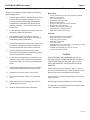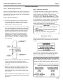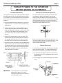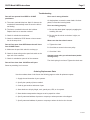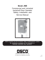
1
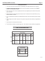
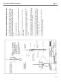
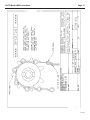
Model JMB
Commercial and Industrial
Jackshaft Door Operator
Safety, Installation, and
Service Manual
Shown with optional chain hoist. Chain guard removed for clarity.
OSCO requires use of an electric edge or photoelectric control
for pedestrian protection on all automatic or
remotely controlled door operators.
OPERATOR SPECIALTY CO., INC.
P.O. BOX 128, CASNOVIA, MI 49318
030205
12-17-97
OSCO Model JMB Instructions
Page 2
Safety Information and Warnings
Read all of the following before beginning to install the
Model JMB operator:
1.
Read the green “SAFETY INSTRUCTIONS” sheet
provided with the operator information. It’s extremely important that the safety warnings and
precautions be understood and followed by the
installing contractor. Leave all instructions with
the end user.
2.
Do not attempt to operate the machine unless it is
completely installed as instructed.
3.
The installation must be made in a neat and
professional manner, observing all rules of good
workmanship and personal safety.
4.
All electrical connections to the power supply must
be made by a qualified and licensed electrician.
All local and national codes must be observed.
5.
A power-disconnect switch should be located
within sight of the operator so that primary power
can be turned off when necessary.
6.
Do not remove the operator cover unless you are
qualified to service this equipment and the power
is turned off. There are no user-serviceable parts
inside.
7.
Install enclosed warning signs so as to be visible
to all persons passing near or through the door.
Features
Mechanical
•
•
•
•
•
•
•
•
•
1/2 HP instant-reverse motor with capacitor, automatic
reset thermal overload
Fully covered power unit
Dependable roller chain drive
Efficient V-belt reduction
Emergency disconnect for manual operation
Magnetic disc brake standard
Available with emergency chain hoist
Door speed 0.8–0.9 feet per second
Right-hand or left-hand mounting
Electrical
•
•
•
•
•
•
•
•
•
Easily adjustable rotary limit switches
Heavy-duty 3-button control station
Heavy-duty contactor starter
Adjustable cutoff switch
24V control circuit
Adapted for pull cord, radio control, or photoelectric control
Adaptable for reversing door edge
Available with adjustable plug-in timer to close
UL listed on standard models
CAUTION
OSCO STRONGLY RECOMMENDS USE OF AN
ELECTRIC EDGE OR PHOTOELECTRIC CONTROL
FOR PEDESTRIAN PROTECTION ON ALL AUTOMATIC OR REMOTELY CONTROLLED DOOR OPERATORS.
8.
Operate the door only when it is in full view.
Children should never be allowed to play on, near, or
around a motorized door. Any control devices should be
placed so as to be inaccessible to small children.
9.
Do not permit children to play on or around the
door.
The door should never be operated unless it is in visual
sight of the user.
10.
Never reach through or around a door frame to
operate the door controls.
Warning signs must be installed on or near the door.
11.
Install all recommended safety equipment.
A pushbutton or keyswitch should not be installed within
reach of the door or operator.
12-17-97
OSCO Model JMB Instructions
Page 3
Installation Instructions
Step 1: Mounting Angle Assembly
Step 4: Electrical Connection
Attach the mounting angles to the power unit, being sure
bolts are positioned at the bottoms of the slotted holes in
the power unit. Drive chain tension can be final adjusted
approximately 1/2 inch.
A complete electrical circuit print can be found inside
the operator cover. The power supply must be of correct
voltage and phase and should be brought into the
operator with no smaller than No. 12 wire. For proper
wire gauge, refer to “Wiring Specifications,” on Page
10. Electrical power must be ample and not taken from
an overloaded line, as faulty operation will result. Proper
thermal protection is supplied with the operator. The
motor contains a thermal overload protector to guard
against overheating due to overload conditions.
Step 2: Operator Installation
A. Locate the large sprocket on the door shaft at the
side of door where the operator is to be mounted.
The sprocket should be located close to the door
shaft bearing. Do not pin at this time.
B. Locate the operator on the wall by use of the bearing
arm, found assembled to the operator output shaft.
To do this, swing the bearing arm above the operator
and slide the bearing onto the door shaft (see the
diagram below). With the operator in this position,
attach the unit to the wall. The operator may be
mounted above or below the shaft, depending on
specifications (see diagram). It can also be hung
from the ceiling or on a shelf, if conditions require
such mounting.
IMPORTANT
A. Power supply must be of correct voltage and
phase.
B. Always disconnect power from the operator
before servicing.
C. Keep clear of the door during operation.
IMPORTANT NOTICE
This operator is supplied with a 3-button control station
(OPEN–CLOSE–STOP) accompanied by a precautionary sign:
It is vital that the 3-button station be mounted within
sight but out of reach of the door and that the warning
sign be mounted adjacent to the 3-button station.
C. Raise the door half open and attach the chain around
the door sprocket and drive sprocket using the
master link provided. Chain should be cut for minimum slack.
D. Adjust chain tension by loosening the bolts in the
bearing arm and the bolts holding the power unit to
the mounting angles. Slide the power unit in the
slotted holes for proper chain tension. Retighten all
bolts securely.
With the sprockets in proper alignment, pin or key the
large sprocket to the door shaft. (The door should be
half open.)
The 3-button station must be connected so the STOP
circuit between terminals #2 & #4 is not bypassed.
Also, if additional 3-button stations are to be connected, the STOP buttons must be wired in series.
NOTE: A STOP button must be used when the installation has radio controls or a single button.
Desired Function
Connecting Terminals
OPENING DEVICE
STOP
CLOSE
OPEN & CLOSE
SAFETY TO REVERSE
24VAC POWER
#1 & #4
#2 & #4
#3 & #4
#4 & #5
#1 & #6
#2 & #10
032498
12-17-97
OSCO Model JMB Instructions
Page 4
TURN OFF POWER TO THE OPERATOR
BEFORE MAKING ADJUSTMENTS!
Limit Switch Adjustment
Clutch and Cutoff Switch Adjustment
Limit switches are wired for mounting the operator below
the shaft on either side of the door with the motor down.
If the operator is to be mounted above the shaft with the
motor up, reverse the limit switch connections at the
switches.
The clutch is set light at the factory and must be properly adjusted in the field according to the size and
weight of the door. Adjust the clutch spring tension so
the operator will drive the door closed without activating
the cutoff switch prematurely. It is best to start with a
light adjustment and tighten one-half turn at a time. Be
careful not to throw cables on the unit.
A. Secure all electrical power connections L1 and L2 on
single-phase or L1, L2, and L3 on three-phase. Turn
the power on.
B. With the door half open, touch the OPEN button. If
the door closes, depress the STOP button immediately. On single-phase operators, reverse motor leads
T1 and T2 at the capacitor. On three-phase operators, reverse any 2 of the 3 power connections (L1
and L2).
C. Depress the CLOSE button. If the door closes, the
operator (and door) should stop when the close limit
nut engages close limit switch. If it does not, press
the STOP button and reverse the limit switch wires.
D. Adjust limit nuts by releasing the spring-loaded detent
plate and turning the nuts in the direction desired (see
the diagram below). One complete turn will allow the
door to move 4–6 inches. Be sure the spring-loaded
detent plate is properly locked into both limit nuts
when adjustment is complete.
Because the cutoff device works in both directions, it is
best to do a preliminary test in the open direction. If the
unit is not sensitive enough, bend the cutoff switch
bracket toward the sprocket.
Manual Disconnect
For your safety and protection, this operator is provided
with a disconnect system. It is recommended that all
persons be well informed of its purpose and operation.
A. To disconnect the operator, open the cover and turn
the thumbscrew out of the engagement disc (see the
diagram below).
B. To re-engage, line up the hole and tighten the thumbscrew.
IMPORTANT: LSO-2 and LSC-2 must be actuated
before LSO-1 and LSC-1. LSO-2
should be actuated three revolutions of
limit shaft before LSO-1.
12-17-97
OSCO Model JMB Instructions
Page 5
Troubleshooting
Door will not operate from OPEN or CLOSE
pushbutton:
A. The motor overload kicked out. Wait 15 minutes; the
overload will automatically reset. Be sure the door is
not binding.
Door runs in wrong direction:
On single-phase, reverse the motor leads. On threephase, reverse two incoming leads.
Door not closing properly:
B. The fuse or overload in the main box is blown.
Replace the fuse or reset the overload.
A. Be sure the detent plate is properly engaging the
travelling limit nuts.
C. Check for a defective transformer.
B. Be sure the drive chain to the door is tight, not
jumping.
D. Check for a defective STOP button or loose connection in the stop circuit.
Door will not open from OPEN button but will close
from CLOSE button:
Motor runs but door doesn’t move:
A. Tighten the clutch.
B. Check the set screw in the motor pulley.
A. Make sure the open limit switch is not hung up.
C. Check the V belt.
B. Check for loose wiring on the open limit switch or the
open coil of the contactor.
Operator stops when you release button (makes
rocking noise):
C. Check for a defective open coil of the contactor.
The clutch spring is too loose. Tighten the clutch nuts.
Door will not close from CLOSE but will open:
Same as preceding, but in reverse.
Ordering Replacement Parts
Use the numbers shown in the lists on the following pages to order all replacement parts.
1. Supply the serial number of your operator.
2. Specify the quantity of pieces needed.
3. Order by part number and name of part.
4. State whether to ship by freight, truck, parcel post, UPS, or air express.
5. State whether transportation charges are to be prepaid or collect.
6. Specify name and address of person or company to whom parts are to be shipped.
7. Specify name and address of person or company to whom the invoice is to be sent.
12-17-97
OSCO Model JMB Instructions
Page 6
12-17-97
OSCO Model JMB Instructions
Page 7
Model JMB
Mechanical Parts List • OSCO Drawing #2120-200
Ref.
No.
Part No.
Description
2100-744
2100-1630
2100-117
2100-954
2100-608
2500-442
2400-472
2100-105
2100-763
2200-074
2100-546
2200-132
2200-151
2500-033
2200-554
2200-039
2200-010
2200-051
2200-150
2200-027
2100-767
2120-154
Main Frame
Bearing Bracket
Bearing Bracket
Operator Cover (JMB only)
Louvered End
Radio Terminal Strip
Pop Rivet
Junction Box
Baffle Panel
Pulley, 6” diameter
Brake Disc
Motor Pulley, 2" diameter
V-Belt, 25"
Standard 3-Button Station
#48 Chain, 14 Links
#48 Chain, 21 Links
#48 Master Link
Sprocket, 41-B-36
#41 Roller Chain, per foot
#41 Master Link
Mounting Angle (2 required)
Spreader Assembly
2110-294
2100-102
2100-759
2200-845
2200-015
2200-105
2400-004
Output Shaft Assembly
Shaft, 1"
Shaft Bracket with Bearing
Sprocket, 48-B-20, 1” bore
Set Collar, 1" x 9/16” LTB
Sprocket, 41-B-16, 1” bore
Key, 1/4" x 1/4" x1"
31
32
2110-635
2200-218
2200-030
2400-188
2400-187
2400-026
2200-195
2110-372
2100-668
2110-181
2200-367
2400-237
2400-061
2400-062
2400-066
2510-181
2500-030
2100-781
Clutch and Cutoff Switch Assembly
Sprocket, 48-B-10, 5/8" bore
Limit Nut
Thrust Washer, 1/16"
Thrust Washer, 1/8"
Spring Pin, 3/16" x 1"
Flange Bearing, 5/8"
Clutch Assembly
Shaft
Sprocket, 48-B-30, 5/8” bore
Clutch Spring
Shear Pin, 3/16" x 1 1/4"
Hex Nut, 5/8"-18
Jam Nut, 5/8"-18
Flat Washer, 5/8"
Cutoff Switch Assembly
Cutoff Switch
Switch Bracket
45
58
59
31
2110-278
2100-769
2100-771
2500-030
Limit Switch Assembly
Detent Plate
Limit Switch Bracket
Limit Switch, SPDT
60
61
2110-360
2100-339
2500-440
Auxiliary Limit Switch Assembly
Limit Switch Bracket
Limit Switch, SPDT
39
41
42
37
29
40
54
55
17
33
34
35
52
76
57
12
70
71
72
73
74
75
27
28
16
21
19
20
22
23
24
25
26
Ref.
No.
Part No.
Description
2110-355
2100-667
2200-195
2110-166
2400-305
2400-188
2110-239
2400-187
2200-233
Intermediate Assembly (JMB only)
Intermediate Shaft
Flange Bearing, 5/8”
Disconnect Hub
Thumbscrew, 3/8”-16 x 3/4”
Thrust Washer, 1/16”
Sprocket, 48-B-10, with Plate
Thrust Washer, 1/8"
Set Collar, 5/8"
2510-068
2510-069
2510-133
2510-199
2510-316
2510-315
2220-004
2100-614
2100-548
2100-949
2200-243
2100-541
2500-178
2500-177
2500-1351
2400-150
Brake Assemblies
115V (JMB, JMB-FD)
230V (JMB, JMB-FD)
115V (JMB-CH only)
230V (JMB-CH only)
460V (JMB, JMB-FD)
460V (JMB-CH)
Brake and Puck Assembly
Lever
Rod (JMB, JMB-FD)
Rod (JMB-CH)
Spring
Mounting Plate
Solenoid, 115VAC
Solenoid, 230VAC
Solenoid, 460VAC
Set Collar, 1/4"
43
2500-416
2500-417
2500-682
Motors
1/2 HP, 115V, 1 Phase
1/2 HP, 208/230V, 1 Phase
1/2 HP, 208/230/460V, 3 Phase
44
2520-207
69
77
78
79
80
81
46
47
48
48
49
50
51
51
2500-212
2500-2084
2500-086
2500-113
2100-113
2500-541
44
2520-208
2500-791
2500-552
2100-772
44
2520-209
44
2520-210
Control Panels
115V, 1 Phase
(WD #2600-222)
Transformer, 115/24V, 40VA
Contactor, 24VAC, 4-Pole
Terminal Strip, 9-141
Capacitor, 64-67 MFD, 330V
Capacitor Clamp
Relay, 3PDT, 24VAC, enclosed
208/230V, 1 Phase
(WD #2600-154)
Transformer, 208/230/24V, 40VA
Capacitor, 20 MFD, 370V
Capacitor Clamp
208/230V, 3 Phase
(WD #2600-155)
2500-791
Transformer, 208/230/24V, 40VA
(Note: This panel has no capacitor)
460V, 3 Phase
(WD #2600-155)
2500-214
Transformer, 460/24V, 40VA
(Note: This panel has no capacitor)
3-2-05
12-17-97
OSCO Model JMB Instructions
Page 8
Parts for Optional Chain Hoist (JMB-CH)
Drawing 2120-171 (Details)
Model JMB-CH
Parts List #159 (JMB Chain Hoist Parts)
OSCO Drawings #2120-171 and #2700-231
Ref.
No.
1
2
3
4
5
6
7
8
9
10
11
Part No.
Description
2110-306
2110-142
2200-403
2100-944
2400-235
2100-957
2500-030
2200-360
2110-251
2200-218
2110-152
2110-439
2200-191
2200-270
2400-146
2100-866
2100-1066
Chain Guide Assembly
Chain Wheel Assembly
Hand Wheel Spring
Intermediate Shaft
Spring Pin, 3/16” x 1 3/4”
Actuator Arm
Limit Switch
Actuator Spring
Actuation Slide Assembly
Sprocket, 48-B-10, 5/8” bore
Cam Plate Assembly
Chain Hoist Intermediate Bracket
Hand Chain, per foot
Cable, per foot
Cable Clamp, 1/8”
Cable Retainer Bracket
Operator Cover (JMB-CH)
Drawing 2700-231 (Detail)
TO HELP PREVENT CHAIN SLIPPAGE, PLACE
HAND CHAIN ON THE HAND WHEEL WITH THE
CUT SIDE OF THE LINK TOWARD THE WHEEL.
4-26-02
12-17-97
OSCO Model JMB Instructions
Page 9
Parts for Optional Floor Disconnect (JMB-FD)
Drawing 2110-293 (Details)
Model JMB-FD
Parts List #160 (JMB Floor Disconnect Parts)
OSCO Drawing #2110-293
Ref.
No.
1
2
3
4
5
6
7
8
9
10
11
12
13
14
Part No.
Description
2110-293
2200-233
2400-187
2110-180
2400-215
2110-095
2200-293
2400-213
2400-088
2100-666
Intermediate Shaft Assembly
Set Collar
Thrust Washer, 1/8”
Disconnect Disc
E-Ring
Shifter Block
Disconnect Spring
Spring Washer, 5/8”
Spring Pin, 3/16” x 1"
Intermediate Shaft
2110-182
2110-133
2100-549
2400-232
2400-169
2200-270
2400-146
2100-866
2100-953
Yoke and Lever Assembly
Fulcrum Assembly
Disconnect Pivot Pin
Spring Pin, 1/4” x 5/8”
Push-On Nut
Cable, per foot
Cable Clamp
Cable Retainer Bracket
Operator Cover (JMB-FD)
4-26-02
12-17-97
OSCO Model JMB Instructions
Page 10
Wiring Specifications
1. From the top chart below, find the section corresponding to the voltage and phase of your operator.
2. The distance shown in the chart is measured in feet from the operator to the power source. DO NOT
EXCEED THE MAXIMUM DISTANCE.
3. When large-gauge wire is used, a separate junction box (not supplied) may be needed for the operator
power connection.
4. Select the gauge for control wiring from the bottom chart. For distances of more than 350 feet, a longdistance interface is required.
5. Wire run calculations are based on the National Electrical Code, Article 430, allowing 5 percent voltage
drop.
6. Supply voltage must be within 10 percent of the operator rating under load conditions (not applicable for
208V).
7. Connect power in accordance with local codes.
8. The wire tables are based on standard copper wire. Wire insulation must be suitable to the application.
USE COPPER WIRE ONLY
Power Wiring
Volts
& HP
Single
Phase
115V
1/2HP
Three
Phase
208V
230V
1/2HP
Max Distance (ft)
Wire
Gauge
Volts
& HP
281
448
713
1133
1802
12
10
8
6
4
208V
230V
620
985
1565
2485
12
10
8
6
Wire
Max Distance (ft) Gauge
1213
1928
3066
4875
7753
12
10
8
6
4
2705
4305
6850
10895
12
10
8
6
1/2HP
460V
1/2HP
Control Wiring
Volts
Max Distance (ft)
Wire
Gauge
24V
250
350
14
12
For distances of more than 350 feet, a
long-distance interface is required.
12-17-97
6. To re-engage the operator, pull the disconnect cable down
and out of the retaining wall bracket.
5. Pull on the chain with a steady medium speed to raise the
door. To avoid over-running the limit switches, be sure not to
raise the door beyond the point at which it would normally
stop if automatically powered.
4. Place the engaged cable back in the wall retainer bracket.
The pre-installed clamp on the cable should be slid under the
bracket shelf to hold the chain hoist engaged.
3. Pull downward on the engagement cable to engage the chain
hoist. This also disengages control power from the door
operator.
2. Remove the chain and engagement cable from the retainer
wall bracket.
1. Be sure the door and track are in good working order and not
jammed.
To use the optional chain hoist:
The jackshaft operator’s optional chain hoist is for use in case
of power failure or malfunction of the automatic operator. When
not in use, the chain and engagement cable should be held in
the retainer bracket up against the wall and to the side of the
doorway.
Instructions for Optional Jackshaft Chain Hoist
OSCO Model JMB Instructions
Page 11
12-17-97
OSCO Model JMB Instructions
Page 12
12-17-97