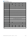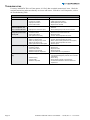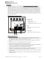
1
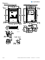
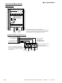
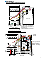
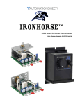
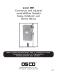
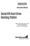
™
GSD5 Series DC Drives User Manual
User Manual Number: IH-GSD5-User-M
IronHorse GSD5 DC Drives User Manual – 1st Ed, Rev A – 12/12/2013
Page 1
~ WARNING ~
Thank you for purchasing automation equipment from Automationdirect.com®, doing business as AutomationDirect. We want your new automation equipment to operate safely. Anyone who installs or uses this equipment
should read this publication (and any other relevant publications) before installing or operating the equipment.
To minimize the risk of potential safety problems, you should follow all applicable local and national codes that
regulate the installation and operation of your equipment. These codes vary from area to area and usually change
with time. It is your responsibility to determine which codes should be followed, and to verify that the equipment,
installation, and operation is in compliance with the latest revision of these codes.
At a minimum, you should follow all applicable sections of the National Fire Code, National Electrical Code,
and the codes of the National Electrical Manufacturer’s Association (NEMA). There may be local regulatory or
government offices that can also help determine which codes and standards are necessary for safe installation and
operation.
Equipment damage or serious injury to personnel can result from the failure to follow all applicable codes
and standards. We do not guarantee the products described in this publication are suitable for your particular
application, nor do we assume any responsibility for your product design, installation, or operation.
Our products are not fault-tolerant and are not designed, manufactured or intended for use or resale as on-line
control equipment in hazardous environments requiring fail-safe performance, such as in the operation of
nuclear facilities, aircraft navigation or communication systems, air traffic control, direct life support machines,
or weapons systems, in which the failure of the product could lead directly to death, personal injury, or severe
physical or environmental damage (“High Risk Activities”). AutomationDirect specifically disclaims any
expressed or implied warranty of fitness for High Risk Activities.
For additional warranty and safety information, see the Terms and Conditions section of our catalog. If you have
any questions concerning the installation or operation of this equipment, or if you need additional information,
please call us at 770-844-4200.
This publication is based on information that was available at the time it was printed. At AutomationDirect we
constantly strive to improve our products and services, so we reserve the right to make changes to the products
and/or publications at any time without notice and without any obligation. This publication may also discuss
features that may not be available in certain revisions of the product.
Trademarks
This publication may contain references to products produced and/or offered by other companies. The product
and company names may be trademarked and are the sole property of their respective owners. AutomationDirect
disclaims any proprietary interest in the marks and names of others.
Copyright © 2013 Automationdirect.com® Incorporated
All Rights Reserved
No part of this manual shall be copied, reproduced, or transmitted in any way without the prior, written consent of
Automationdirect.com® Incorporated. AutomationDirect retains the exclusive rights to all information included
in this document.
Page 2
IronHorse GSD5 DC Drives User Manual – 1st Ed, Rev A – 12/12/2013
Contents
WARNING���������������������������������������������������������������������������������������������������������������������������������������������������������������������� 2
Trademarks���������������������������������������������������������������������������������������������������������������������������������������������������������������������� 2
GSD5 DC Drives User Manual Overview ����������������������������������������������������������������������������������������������������������������������� 3
IronHorse GSD5 Series DC Drives General Information����������������������������������������������������������������������������������������������� 4
Selection and Specifications ������������������������������������������������������������������������������������������������������������������������������������������� 5
Dimensions ���������������������������������������������������������������������������������������������������������������������������������������������������������������������� 6
Installation and Wiring���������������������������������������������������������������������������������������������������������������������������������������������������� 7
Start-Up ����������������������������������������������������������������������������������������������������������������������������������������������������������������������� 12
Trim Pot Adjustments ��������������������������������������������������������������������������������������������������������������������������������������������������� 12
Troubleshooting ����������������������������������������������������������������������������������������������������������������������������������������������������������� 14
GSD5 Series Accessories �������������������������������������������������������������������������������������������������������������������������������������������� 15
GSD5 DC Drives User Manual Overview
Overview of this Publication
The IronHorse GSD5 Series DC Drives User Manual describes the installation, configuration, and
methods of operation of the GSD5 Series DC Drives.
All information contained in this manual is intended to be correct. However, information and data in this
manual are subject to change without notice. AutomationDirect (ADC) makes no warranty of any kind
with regard to this information or data. Further, ADC is not responsible for any omissions or errors or
consequential damage caused by the user of the product. ADC reserves the right to make manufacturing
changes which may not be included in this manual.
Who Should Read This User Manual
This manual contains important information for those who will install, maintain, and/or operate any of the
GSD5 Series DC Drives.
Technical Support
By Telephone: 770-844-4200 (Mon.–Fri., 9:00 a.m.–6:00 p.m. E.T.)
On the Web: www.automationdirect.com
Our technical support group is glad to work with you in answering your questions. If you cannot find
the solution to your particular application, or, if for any reason you need additional technical assistance,
please call Technical Support at 770-844-4200. We are available weekdays from 9:00 a.m. to 6:00 p.m.
Eastern Time.
We also encourage you to visit our web site where you can find technical and non-technical information
about our products and our company. Visit us at www.automationdirect.com.
Special Symbols
When you see the “notepad” icon in the left-hand margin, the paragraph to its
immediate right will be a special note.
When you see the “exclamation mark” icon in the left-hand margin, the paragraph to its immediate right
will be a WARNING. This information could prevent injury, loss of property, or even death (in extreme
cases).
IronHorse GSD5 DC Drives User Manual – 1st Ed, Rev A – 12/12/2013
Page 3
IronHorse GSD5 Series DC Drives General Information
IronHorse GSD5 DC drives are versatile, general-purpose, variable-speed, DC motor controllers that
are designed to control DC Permanent Magnet, Shunt Wound, and some Universal (AC/DC) motors.
Incoming AC voltage is converted to adjustable full-wave rectified DC voltage to operate the DC motor.
Also, a full-wave field voltage is provided for shunt wound motors.
Carefully check the DC Drive for shipping damage. Report any damage to the
carrier immediately. Do not attempt to operate the drive if visible damage is
evident to either the circuit or to the electronic components.
Standard Features
• Input voltages 120/240VAC @ 50/60Hz; output 0–90/180VDC.
• Adjustable horsepower settings (1/8 thru 1hp @ 120 VAC input; 1/4 thru 2hp @ 240 VAC input).
• Barrier terminal strip for all power and control wiring.
• Full-wave bridge supply.
• 1% speed regulation with armature voltage feedback; ±1/2% with tachometer feedback.
• Adjustable Minimum speed, Maximum speed, IR Compensation, Current Limit, and Acceleration &
Deceleration.
• Line voltage compensation.
• 5kΩ speed potentiometer with leads, dial, and knob included.
• 50:1 speed range.
• Transient voltage protection.
• Voltage following mode or DC tachometer follower by supplying ungrounded 0–12VDC analog input
signal.
• DC tachometer feedback (6V at base speed).
• Inhibit circuit permits start & stop without breaking AC lines.
• Shunt field supply provided.
• Available in NEMA 4/12 enclosure with Power ON/OFF switch, or open-frame chassis.
Control Features
MINIMUM SPEED – Allows adjustment of the motor speed when the speed pot is set at minimum
(CCW). This permits the user to eliminate “Deadband” on the main speed control, permitting zero
calibration. Clockwise rotation of “MIN” trim pot increases speed.
MAX SPEED (Maximum Speed) – Allows adjustment of the motor speed when the speed pot is set at
maximum (CW). This permits the user to eliminate the top end “Deadband”, which will provide full
speed at maximum rotation. Rotation of the “MAX” trim pot in the clockwise direction increases the
maximum motor speed.
ACCEL (Acceleration) – Allows adjustment of the motor acceleration from a minimum of 0.5 seconds to
approximately 8.0 seconds. The deceleration time is proportional to the ACCEL setting.
I.R. COMP (Speed Regulation) – Adjusts the drive output to compensate for speed changes caused by
varying motor loads. As motor load is increased, IR COMP increases the voltage output of the drive.
Clockwise rotation of the “IR COMP” trim pot increases compensation.
CUR. LIM. (Current Limit) – Provides protection from excessive armature current by limiting the
maximum armature current the drive can provide. This enables adjustment of the maximum torque the
motor can deliver. Torque adjustment (CUR. LIM.) is preset at 125% of rated motor torque (current)
based on horsepower. Clockwise rotation of the “CUR. LIM.” trim pot increases the torque (current) the
drive will provide.
INHIBIT TERMINAL PIN – An adjustable acceleration ramp that allows the user a choice of stopping
and starting hard (fast), or stopping hard with a soft start (without breaking the AC lines).
Page 4
IronHorse GSD5 DC Drives User Manual – 1st Ed, Rev A – 12/12/2013
Selection and Specifications
GSD5 Series DC Drives – Selection & Specifications
Model
Package Configuration
GSD5-240-10C
GSD5-240-10N4
GSD5-240-10N4-A
open frame
GSD5-240-10N4-R
GSD5-240-10N4-V
NEMA 4/12
1.4
Power Quality Form Factor
–
Special Features
current follower
manual reversing
0–90/180 VDC
Output Voltage
100VDC @ 120VAC input ; 200VDC @ 240VAC input ; (1A max)
Shunt Field Voltage
1/8 – 1 hp @ 90VDC ; 1/4 – 2 hp @ 180VDC
Motor Rating (hp)
150mA – 10A (DC)
Output Current (continuous)
Current Overload Capacity
150% for 60s
Current Limit (adjustable)
1.0–15.0A (DC)
Metal Oxide Varistor (MOV)
Transient Protection
I.R. Compensation
adjustable
Speed Adjustment
5kΩ 2W potentiometer or 0–10VDC isolated input signal
50:1
Speed Range
±1% of base speed
Speed Regulation
Maximum Speed
adjustable from 66% to 110% of base speed
Minimum Speed
linear ramp 0–30% of adjustable maximum speed
Acceleration
linear ramp adjustable 0.5–8.0 seconds
Deceleration
proportional to acceleration ramp (not independently adjustable)
no
Dynamic Braking
Plugging Capability **
no
Electrical Connections
barrier-type terminal strip; ; 26–12 AWG
Bussman ABC or Littlefuse 314 series ceramic fuses or equivalent
Refer to “Installation and Wiring” section for details.
External Fusing Required
-10 to 45 °C [14 to 113 °F]
Operating Temperature
current limiting
Thermal Protection
can be mounted in any orientation
Mounting Orientation
NOT compatible with any corrosive gases
Corrosive Gases
Weight
voltage follower
120/240 VAC ±10%
Input Voltage (@50/60Hz)
16.25 oz [413g]
25.50 oz [723g]
CULUS
Agency Approvals
Listed (E333109), RoHS
RoHS
Optional Accessories *
Replacement Potentiometer
GSDA-5K
Digital Potentiometer
GSDA-DP
GSDA-MREV
–
–
included
–
Analog Current Input Card
GSDA-AI-A
–
included
–
–
Analog Voltage Input Card
GSDA-AI-V5
–
–
–
included
Manual Reverse Switch
* For accessories details, please visit www.AutomationDirect.com.
** Plugging is a method of rapidly changing motor direction by reversing motor armature polarity, while the motor is still running.
IronHorse GSD5 DC Drives User Manual – 1st Ed, Rev A – 12/12/2013
Page 5
Dimensions
GSD5-240-10C (dimensions = in [mm])
GSD5-240-10N4-x (dimensions = in [mm])
Speed Pot
Page 6
IronHorse GSD5 DC Drives User Manual – 1st Ed, Rev A – 12/12/2013
Installation and Wiring
Install open-frame drives in an enclosure with a volume at least three
times the volume of the open-frame drive.
Do not mount GSD5-240-xxxxx DC drive where ambient temperature is
outside the range of -10 to 45 °C (14 to 113 °F).
Size all wires that carry armature or line currents as specified by
applicable national, state, and/or local codes. All other wires may be
18AWG or smaller as permitted by the codes.
Separate control wires from the armature and AC lines when routed in
conduit or wire trays.
CAUTION!! Turn power OFF while making wiring connections.
Improper installation or operation of this DC Drive may cause injury to personnel or drive
failure. The drive must be installed in accordance with local, state, and national safety codes.
Make certain that the power supply is disconnected before attempting to service or remove any
components!!! If the power disconnect point is out of sight, lock it in disconnected position
and tag it to prevent unexpected application of power. Only a qualified electrician or service
personnel should perform any electrical troubleshooting or maintenance. At no time should
circuit continuity be checked by shorting terminals with a screwdriver or other metal device.
Before attempting to wire the DC Drive, make sure all power is disconnected. Recheck code
designation to assure proper voltage is present for the DC Drive. Carefully select proper wire
size for current and voltage drop. Limit the voltage drop through the wiring to 5% of the line
voltage at full load
CAUTION!! Do not attempt to perform a hi-pot test across the AC lines with the DC drive in
the circuit. This will result in immediate or long-term damage to the drive.
1) Ensure that the GSD5 drive chassis is properly grounded.
2) Motor armature connections must not be switched or broken while the GSD5 drive is ON.
Serious damage may result.
3) The inputs to the speed pot terminals (P1-1, P1-2, P1-3) must not be grounded.
Serious damage may result.
Fusing
The GSD5 has an internal fuse in AC line 1 (P1-11), and this fuse is sized to open in the event of a
shorted armature or if an armature line is shorted to earth ground. For properly connected 120 VAC input,
additional fusing is not needed.
For 240 VAC applications, use an external fuse in AC line 2 (P1-10). This fuse should be a Bussman
ABC10 or LittleFuse 314-010.
(AutomationDirect sells ABC series fuses.)
AC current is determined by motor characteristics, and it may be
necessary to increase fuse value for some applications.
Wiring Terminals
GSD5 Wiring Terminals
Type
Wire Range
Tightening Torque
barrier-type terminal strip
26–12 AWG
10.0 lb·in [1.1 N·m]
IronHorse GSD5 DC Drives User Manual – 1st Ed, Rev A – 12/12/2013
Page 7
Installation and Wiring (continued)
Wiring Diagrams
GSD5-240-10C Basic Wiring Diagram
Min
Max
IR
Accel Comp
Cur
Lim
Customer Installed
Speedpot
(factory provided
with 8-inch leads)
Inhibit
Pin P2
orange white
red
AC1
AC2
spare
spare
–Field
+Field
–Arm
+Arm
Wiper
Pot Hi
Pot Lo
P1 1 2 3 4 5 6 7 8 9 10 11
field*
AC input **
motor
chassis
armature
ground
* Field terminals are used for shunt-wound motors only!
Do not connect these terminals when using permanent-magnet motors.
** AC1 terminal is internally fused; AC2 terminal is NOT internally fused.
Add external fuse for AC2 if it is connected to a hot AC line.
GSD5-240-10C Reversing Wiring Diagram
-Armature / -Field (P1-4)
+Armature (P1-5)
Customer supplied
4PDT Center-off
Center-Blocked switch
(GSDA-MREV shown)
VAC Input (N) (P1-10)*
VAC Input (L) (P1-11)*
GSD5-240-10C
* AC1 (P1-11) terminal is internally fused;
AC2 (P1-10) terminal is NOT internally fused.
Add external fuse for AC2 if it is connected
to a hot AC line.
AC1* (L)
Page 8
Direction 1 (forward or reverse)
OFF (no wire terminal)
Direction 2 (reverse or forward)
AC2* (N)
Arm1
Arm2
IronHorse GSD5 DC Drives User Manual – 1st Ed, Rev A – 12/12/2013
Installation and Wiring – Wiring Diagrams (continued)
GSD5-240-10N4 Basic Wiring Diagram
FACTORY PREWIRING
Min
IR
Accel Comp
Max
HI (white)
WIPER (red)
LO (orange)
Cur.
Lim.
DPST SWITCH
SPEEDPOT
(black)
(white
or
yellow)
(white)
(black
or brown)
Inhibit P2
Pin
INSIDE OF COVER
Switched AC1
AC
Switched AC2
-Field
AC
+Arm
+Field
Wiper
Pot Lo
Pot Hi
-Arm
P1 -1 -2 -3 -4 -5 -6 -7 -8 -9 -10 -11
CUSTOMER WIRING
chassis
ground
field*
motor
armature
* Field terminals are used for shunt-wound motors only!
Do not connect these terminals when using
permanent-magnet motors.
** AC1 terminal is internally fused; AC2 terminal is NOT
internally fused. Add external fuse for AC2 if it is
connected to a hot AC line.
ac input**
Endplate with holes for 1/2" NPT conduit
GSD5-240-10N4-V Basic Wiring Diagram
(Factory installed Voltage Follower input option)
FACTORY PREWIRING
Min
Max
Accel
IR
Comp
Cur.
Lim.
NOTE: SOME
FACTORY WIRING
IS NOT SHOWN
FOR CLARITY
3PDT Switch
(yellow)
(brown)
Speedpot
(red) (white)
(black)
(orange)
(white)
(black)
P2
(brown)
Inhibit
Pin
(red)
P2
Vin or 4-20mA
CONNECTOR
(white)
(white)
(orange)
RANGE
JUMPER
CONNECTOR*
(yellow)
Switched AC
AC
Switched AC
AC
-Field
+Field
+Arm
Wiper
Pot Hi
-Arm
Pot Lo
P1 -1
-1 -2 -3 -4 -5 -6 -7 -8 -9 -10 -11
BALANCE
TRIMPOT
JP2
P4
4-20 Vin
-1 -2 -3
(blue)
GAIN
TRIMPOT
* Jumper clip is used to select
input voltage range. When
installed from P4-1 to P4-2,
the range is 0–25 VDC thru
0–250 VDC. When installed
from P4-2 to P4-3, the range
is 0–5 VDC thru 0–25 VDC.
P3
P5
GSD5-240-10N4-V
(INSIDE OF COVER)
CUSTOMER WIRING
INPUT IMPEDANCE:
motor
ac input
1.2MW on high scale
150KW on low scale
IronHorse GSD5 DC Drives User Manual – 1st Ed, Rev A – 12/12/2013
analog
speed
common
analog
speed
signal
Page 9
Installation and Wiring – Wiring Diagrams (continued)
GSD5-240-10N4-R Reversing Wiring Diagram
(Factory installed Manual Reversing input option)
The GSD5-240-10N4-R includes a 4PDT blocked center switch which permits reversing the motor.
When switched between the forward/reverse positions, a delay is encountered due to the blocked center
position, which protects the control from any voltage that may be at the armature terminals. The center
position is OFF/NEUTRAL.
Caution: The motor must come to a complete stop before changing directions. If the motor
does not come to a complete stop, the drive may be seriously damaged. Bypassing the center
block of the switch may result in serious damage to the drive.
4PDT SWITCH
Min
IR
Accel Comp
Max
HI (white)
WIPER (red)
LO (orange)
Cur.
Lim.
(black)
SPEEDPOT
(white)
(red)
(gray)
(blue)
brown)
Inhibit P2
Pin
(purple)
(yellow)
INSIDE OF COVER
Switched AC1
AC
Switched AC2
-Field
AC
+Arm
-1 -2
+Field
Wiper
Pot Hi
-Arm
Pot Lo
P1 -1 -2 -3 -4 -5 -6 -7 -8 -9 -10 -11
field*
chassis
ground motor
armature
ac input
* Field terminals are used for shunt-wound motors only!
Do not connect these terminals when using
permanent-magnet motors.
** AC1 terminal is internally fused; AC2 terminal is NOT
internally fused. Add external fuse for AC2 if it is
connected to a hot AC line.
P3
Endplate with holes for 1/2" NPT conduit
GSD5-240-10N4-A Basic Wiring Diagram
(Factory installed Current Follower input option)
The GSD5-240-10N4-A includes a 4–20 mA isolated signal card that allows the drive to be run in either
the Manual mode via a speed pot, or the Auto mode via the 4–20 mA signal.
BALANCE
ADJUSTMENT
LINEARITY/GAIN
ADJUSTMENT
RED
AUTO
125
CURRENT
SOURCE
3PDT
SWITCH
JU2
JU1
JU3
MANUAL
P16
+
-
AC AC
250/500
-1
-2
-3
-4
-5
-6
-7
-8
-9 -10 -11 P1
(GSD5 TERMINAL STRIP)
from P1-2 of GSD5
YELLOW
WHITE
HI
SPEEDPOT
Page 10
W
RED
LO
ORANGE
IronHorse GSD5 DC Drives User Manual – 1st Ed, Rev A – 12/12/2013
Installation and Wiring – Wiring Diagrams (continued)
GSD5-240-xxx Dynamic Braking
GSD5-240-xxx Two-Speed Operation
A DPDT switch is used to control and to connect a
customer-supplied Dynamic Braking Resistor (DBR).
Typical values for the DBR are 35–50W at 5Ω for 120V,
or 10Ω for 240V. Motor horsepower, inertia, and cycle
time affect the sizing of the DBR.
Two-speed operation is done using two
10 kΩ speed potentiometers in parallel,
with both Highs connected to terminal
P1-3, and both Lows connected to
P1-1. A SPDT switch selects which
pot Wiper is connected to terminal
P1-2.
P2 INHIBIT
LO
P1
W
1
2
SPDT
W
HI
HI
HI
3
DPDT SWITCH (N.C.)
2
W
LO
LO
GSD5xxx-xxxx
GSD5-xxx-xxxx
(2) 10kΩ Speedpots
P1
1
3
4
MOTOR
5
DYNAMIC
BRAKE
RESISTOR
6
GSD5-240-xxx Tachometer Feedback
GSD5-240-xxx Tachometer Follower
Improves regulation to ± 1/2 of base speed.
Allows drive output to follow tachometer
voltage.
P2 Inhibit
+
1000 rpm for 1800 rpm motor)
–
P1-2 Pot Wiper
+
Tachometer 6VDC at Base Speed (3VDC at
Tachometer
P1-4 -Arm
12 VDC at Full Speed
–
P1-1 Pot Lo
Tachometer control needs tachometer output of 7VDC/1000rpm with ripple
limited to 1% or less.
GSD5-240-xxx Inhibit (used independently)
GSD5-240-xxx Inhibit (used with speed pot)
The customer-supplied SPST switch is
connected in series between the Speed Pot
High (P1-3) and the Inhibit pin (P2). To
inhibit (stop motor), close Speed Pot High to
the Inhibit pin. To restart, return the switch to
open.
The common of the SPDT switch is connected
to control pot High, and is switched between
Speed Pot High (P1-3) and the Inhibit pin (P2).
To inhibit (stop motor), Speed Pot High is
closed to the Inhibit pin. To restart, return the
switch to Speed Pot High.
P1
SPEEDPOT
LO
1
WIPER
2
HI
3
INHIBIT
(P2)
SPST
SPEEDPOT
P1
1
LO
2
WIPER
3
HI
INHIBIT
(P2)
SPDT
1) Inhibit control will stop and start the motor quickly.
2) Inhibit control permits starting and stopping the motor without
breaking the AC lines.
3) In the event of SCR failure or false triggering, the Inhibit circuit
will not stop the motor.
4) Always use shielded wire when connecting to the Inhibit terminal, and
connect the shield to the -Armature or Common of the drive.
IronHorse GSD5 DC Drives User Manual – 1st Ed, Rev A – 12/12/2013
Page 11
Start-Up
1) Recheck all wiring. Accidental grounds, loose or pinched wires on armature or speed pot wires may
damage the DC drive when power is applied.
2) Check to see that the incoming power is of the correct voltage.
3) Turn the speed pot to zero (fully CCW).
4) Turn power on, and advance the speed pot while observing motor direction of rotation.
Power must be turned off again before step 5 can be accomplished!
5) If the motor rotation is incorrect, turn power off at external disconnect, and reverse the +ARM and
-ARM connections.
6) Check for satisfactory operation throughout the speed range.
7) If operation is satisfactory, no readjustments are needed.
8) If instability or surging is observed, or if maximum speed is higher than desired, refer to the “Trim Pot
Adjustments” section.”
9) For other problems, consult the “Troubleshooting” section.
Trim Pot Adjustments
If the system is unstable after the previous Start-Up procedure, then adjust the trimpots as follows.
These adjustments are maintained, and periodic readjustments are not normally needed. However,
readjustments could be needed if the drive is operated beyond ±10% of the rated line voltage.
For GSD5 Drives without Analog Current/Voltage Input Cards
GSD5-240-10C, GSD5-240-10N4, GSD5-240-10N4-R Trim Pot Adjustment *
Trim Pot
Function
Adjustment
Max
Sets maximum motor speed
when speed pot is set at
maximum (fully CW rotation).
CW rotation of MAX trim pot
increases maximum motor
speed.
1)
2)
3)
4)
5)
Min
Sets minimum motor speed
when speed pot is set at
zero. CW rotation will
increase minimum motor
speed.
1) Set Speed pot to zero (fully CCW).
2) Rotate MIN trim pot CW until motor starts to rotate.
3) Slowly rotate MIN trim pot CCW until motor stops.
NOTE: If motor rotation is desired, rotate MIN trim pot CW until desired MIN
speed is reached.
IR Comp
Calibrates speed regulation. Provides a means
of improving motor speed
regulation in the armature
feedback mode. If a
slowdown due to load
change is of no concern,
rotate this trim pot fully CCW.
1)
2)
3)
4)
Cur Lim
Limits DC motor armature
current (torque) to prevent
damage to the motor or
drive. The current limit is set
for the rated motor current.
CW rotation of this trim pot
increases the armature
current (or torque produced).
1) TURN DRIVE POWER OFF!
2) Connect a DC Ammeter between A1 on motor and +ARM on drive. This is in
series with the motor.
3) Turn power ON.
4) Set Speed pot at the 50% position.
5) Apply friction braking to motor shaft until motor stalls (zero rpm).
6) With motor stalled, set current at 125% of rated motor armature current by
adjusting CUR. LIM. trim pot.
Accel
Allows adjustment of acceleration by user.
1) CW rotation of the ACCEL trim pot increases acceleration time.
TURN DRIVE POWER OFF!!
Connect a DC voltmeter: + to +ARM; - to -ARM.
Set meter voltage range: (90 VDC for 120 VAC; 180 VDC for 240 VAC).
Turn power on. Set Speed pot at 100%.
Adjust MAX trim pot to rated motor armature voltage as shown on meter.
NOTE: A tachometer or strobe may be used in lieu of a meter.
Follow above steps, except adjust MAX trim pot to rated motor base speed
indicated by tachometer or strobe.
Set Speed pot at 50%.
Observe motor speed at no load condition.
Apply full load to motor.
Turn IR COMP trim pot CW to obtain the same motor speed as with no load.
* Adjustments are performed with motor connected to drive.
DO NOT USE this adjustment procedure for GSD5-240-10C DC drives with GSDA-AI-A analog current input cards,
for GSD5-240-10N4-A drives, or for GSD5-240-10N4-V drives.
Page 12
IronHorse GSD5 DC Drives User Manual – 1st Ed, Rev A – 12/12/2013
Trim Pot Adjustments (continued)
For GSD5-240-10C with optional GSDA-AI-A Analog Current Input Card, and GSD5-240-10N4-A
(Adjustments are performed with motor connected to drive.)
1) Adjust the DC drive Min trim pot to minimum (full CCW) and Max trim pot to 50%. (The voltage is
set below the typical motor voltage to make certain the drive is NOT in saturation before setting the
analog current input board saturation point.
2) Set the Linearity/gain pot on the analog current input full CW. This is a 20-turn pot and you should
hear a clicking with each turn when fully up or just count 20 turns.
3) Make certain your motor is connected to +/-ARM output of the drive, the AUTO/MAN switch is in
AUTO mode (for GSD5-240-10N4-A), and source power for the drive is turned on. (Note: For proper
tuning, this setup is best done on an unloaded motor.)
4) With power applied and a voltmeter monitoring motor output VDC, apply 4mA to analog current
input board. Check voltmeter reading and adjust the Linearity/gain trim pot, R16, on the analog
current input board CCW until motor output voltage is less than 0.1VDC.
5) Now apply 20mA to the analog current input board and adjust the Max trim pot to a voltage that is
15 volts above the final desired max motor voltage output. Adjust the Linearity/gain trim pot on the
analog current input board CCW until the motor output voltage decreases to the desired max voltage
setpoint.
6) Now, apply 4mA to the analog current input board again, and adjust the Min trim pot to deadband
or the desired minimum motor voltage output. The deadband point is where you are at 0VDC, and
any further increase of the Min trim pot would result in an output to the motor. Re-apply 20mA to
the analog current input board and verify max output has not changed. A small adjustment may be
needed to the Max trim pot to reset to desired max output.
7) Adjust 4-20 input to 12mA. If tuned properly the output voltage of an unloaded motor should be
within a few volts of ½ output (based on max output setting above).
8) GSD5-240-10N4-A option only: With 20mA applied to the GSD5-240-10N4-A in Auto mode,
move AUTO/MANUAL switch to MANUAL.
In manual mode, turn the speed pot full CW and note motor voltage output reading on voltmeter. If
not equal to output at 20mA in Auto Mode, adjust the Balance trim pot on the GSD5-240-10N4-A
board (CW or CCW) until the same reading is achieved. The motor output VDC should not change
more than 1VDC when flipping back and forth between AUTO and MANUAL position.
FOR GSD5-240-10N4-V
(Adjustments are performed with motor connected to drive.)
1) With NO power at the drive, connect a DC voltmeter (meter must not be grounded) to control outputs
as follows: Meter COMMON to the -ARM terminal; Meter POSITIVE to the +ARM terminal. Select
correct meter range (0-90V or 0-180V).
2) Preset GAIN trim pot (analog voltage follower board) fully CCW, place input voltage range jumper clip
in proper position. (For ranges, refer to the GSD5-240-10N4-V Basic Wiring Diagram on page 9.)
3) Preset control as follows: MIN and IR COMP fully CCW; MAX at 50%.
4) Apply desired AC voltage to drive and analog voltage follower board.
5) With 0 volts into analog voltage follower board, adjust MIN trim pot on drive to eliminate deadband.
To do this, increase MIN fully CW, and then adjust CCW until meter reads 0V.
6) Apply maximum input voltage to analog voltage follower board input.
7) Adjust GAIN until no further change in voltage output occurs, then turn CCW until a 5V drop occurs,
and then set control MAX to 90VDC (for 120V input) or 180VDC (for 240V input).
8) For Closed Loop systems the IR COMP should remain fully CCW. For Open Loop systems, set IR per
set-up procedure.
9) Some interaction between trimpots may occur. Recheck the MIN trim pot setting and repeat steps 5
through 7 as needed.
IronHorse GSD5 DC Drives User Manual – 1st Ed, Rev A – 12/12/2013
Page 13
Troubleshooting
If a newly installed DC Drive will not operate, it is likely that a terminal connection is loose. Check the
terminal connections and ensure that they are secure and correct. If the drive is still inoperative, refer to
the Troubleshooting Table.
Troubleshooting
Problem
Possible Cause(s)
Corrective Action
Motor doesn’t run
1)
2)
3)
4)
1)
2)
3)
4)
Armature output voltage
cannot be adjusted; output is a constant DC level
1) No motor or load connected
Blown fuse or circuit breaker
Incorrect or no power
Speed pot set at zero
Worn motor brushes
2) Speed pot low connection open
1) Ensure that motor or load is connected to armature
terminals
2) Ensure that Speed pot Low wire is connected
Motor stalls, or runs very
slowly with speed control
set fully CW
1)
2)
3)
4)
Low voltage
Overload condition
Worn motor brushes
Max speed set incorrectly
1)
2)
3)
4)
Ensure that VAC is above 108 VAC
Reduce load or increase motor size
Replace brushes
Consult “Trim Pot Adjustments” section
Motor “hunts”
1)
2)
3)
4)
5)
Too much IR Comp
Motor is in Current Limit
Motor not pulling enough current
Max trim pot set too high
Motor speed is above rated speed
1)
2)
1)
2)
3)
Consult “Trim Pot Adjustments” section
Consult “Trim Pot Adjustments” section
Motor current must be greater than 150 mA (DC)
Consult “Trim Pot Adjustments” section
Reduce speed
Repeated fuse blowing
1)
2)
3)
4)
5)
Low voltage
Overload condition
Worn motor brushes
Defective motor bearings
Defective electrical components
1)
2)
3)
4)
5)
Ensure that VAC is above 108 VAC
Reduce load
Replace brushes
Replace bearings
Contact distributor or representative
Motor runs, but will not
stop
1) Incorrect wiring (enclosed drive)
2) Defective wiring
3) Jumper inhibit
4) Defective component
Page 14
Replace fuse or reset breaker
Install proper power service
Rotate Speed pot CW to start
Replace motor brushes
1) Ensure that Terminal Strip Wiring is correct per wiring instructions/diagrams (check AC line connection
in particular)
2) Check wiring
3) Check jumper inhibit pin connection (P2)
4) Contact AutomationDirect “Product Returns” for
replacement.
IronHorse GSD5 DC Drives User Manual – 1st Ed, Rev A – 12/12/2013
GSD5 Series Accessories
GSDA-AI-V5
Optional analog voltage or current input card for open-frame GSD5-240-10C series DC drives only
This option card allows for the use of either a grounded or non-grounded remote DC signal such as 0–5
VDC through 0–250 VDC, 4–20mA, or a remote speed potentiometer. The DC input signal type can be
selected for voltage (Vin) or current (4–20mA) via the JP2 jumper clip. There is a Hi/Lo range jumper
(P4) selection that should be set to the (Lo) setting when using a 4–20mA signal or voltage ranges of 0–5
VDC through 0–25 VDC. When using voltage ranges of 0–25 VDC through 0–250 VDC, this jumper
must be set to (Hi). The GAIN trim pot is used to set full linear output in reference to the input signal
range. The output of this remote signal isolation board is a linear signal that is proportional to the remote
input signal being supplied.
GSDA-AI-V5 Mounting and Wiring Diagram
MIN
MAX
ACCEL
IR COMP
CUR LIM
The Kit Includes:
• (1) option card
• (3) spacers (0.25 x 0.5 in)
• (3) Phillips-head screws (#6-32 x 0.75 in)
Vin or 4-20mA
CONNECTOR
RANGE
JUMPER
CONNECTOR
GAIN
TRIMPOT
P3
P1
-1
JU2
-2
-3
P4
-1
-2
-3
Spacers:
P2
4-20
Vin
JP2
Install spacers at JU1, JU3, and JU5, as
illustrated.
JU4
AC
POT LO
ORANGE
JU3
JU1
GSD5-240-10C with
GSDA-AI-V5 installed
JU5
-ARM
+ARM
AC1
Wiring Jumpers:
Connect wires JU2 and JU4 as illustrated.
AC2
CUSTOMER CUSTOMER
COMMON
SIGNAL
GSDA-AI-V5 Setup Procedure
1) With motor connected and NO power at the drive, connect a DC voltmeter (meter must not be
grounded) to control outputs as follows: Meter COMMON to the -ARM terminal; Meter POSITIVE to
the +ARM terminal. Select correct meter range (0-90V or 0-180V).
2) Preset GAIN trim pot (analog voltage follower board) fully CCW, place range jumper clip in proper
position.
3) Preset control as follows: MIN and IR COMP fully CCW; MAX at 50%.
4) Apply desired AC voltage to drive and analog voltage follower board.
5) With 0 volts into analog voltage follower board, adjust MIN trim pot on drive to eliminate deadband.
To do this, increase MIN fully CW, and then adjust CCW until meter reads 0V.
6) Apply maximum input voltage to analog voltage follower board input.
7) Adjust GAIN until no further change in voltage output occurs, then turn CCW until a 5V drop occurs,
and then set control MAX to 90VDC (for 120V input) or 180VDC (for 240V input).
8) For Closed Loop systems the IR COMP should remain fully CCW. For Open Loop systems, set IR per
set-up procedure.
9) Some interaction between trimpots may occur. Recheck the MIN trim pot setting and repeat steps 5
through 7 as needed.
IronHorse GSD5 DC Drives User Manual – 1st Ed, Rev A – 12/12/2013
Page 15
Literature Number: LT141
Drawing Number: A-5-3903A
Page 16
IronHorse GSD5 DC Drives User Manual – 1st Ed, Rev A – 12/12/2013