1
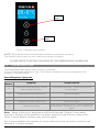
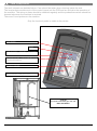
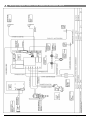
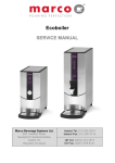
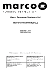
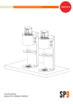
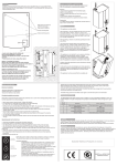
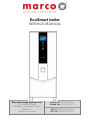
EcoSmart boiler
SERVICE MANUAL
Marco Beverage Systems Ltd.
63d Heather Road,
Sandyford Industrial Estate,
Dublin 18,
Republic of Ireland
Ireland Tel: (01) 295 2674
Ireland Fax: (01) 295 3715
UK Tel: (0207) 274 4577
UK Fax: (0207) 978 8141
CONTENTS:
1.
2.
INTRODUCTION
SAFETY INSTRUCTIONS
3
4
3.
BASIC INSTRUCTIONS
Installation Details
Troubleshooting
Maintenance
Cleaning
Limescale
Cautions and Safety Tips
4
4
5
6
6
6
6
TECHNICAL DATA
General Description
External Arrangement
Access to internal components
Internal Arrangement
PCBs
PCB EcoSlave -1600354
PCB EcoSmart Display – 1600357
PCB EcoSmart Display Label Requirements
1000677/100678
Troubleshooting – Diagnostic guide
Tank Components
Descaling procedure
Wiring Diagram 1000677 EcoSmart PB10
Wiring Diagram 1000678 EcoSmart HiDeck
Spare Parts List
7
7
7
8
10
11
11
12
3.1.
3.2.
3.3.
3.4.
3.5.
3.6.
4.
4.1.
4.2.
4.3.
4.4.
4.5.
4.5.1.
4.5.2.
4.5.3.
4.6.
4.7.
4.8.
4.9.
4.10.
4.11.
Service Manual 1000677 EcoSmart PB10 1000678 EcoSmart hiDeck 221110.doc
12
13
15
16
17
18
19
Page 2 of 19
1. INTRODUCTION:
The information provided in this manual is intended to assist in the installation and maintenance of
the Marco EcoSmart Boiler. Please read the instructions carefully to prevent accidents and ensure an
efficient installation.
This manual is not a substitute for any safety instructions or technical data affixed to the machine or
its packaging. All information in this manual is current at the time of publication and is subject to
change without notice.
Only technicians or service providers authorised by Marco should carry out installation and
maintenance of these machines.
Marco accepts no responsibility for any damage or injury caused by incorrect or unreasonable
installation and operation.
2. SAFETY INSTRUCTIONS:
Read all instructions.
To protect against electric shock do not immerse mains cord in water or other liquid.
To prevent chafing of the cable, do not let the mains cord hang over the edge of a table or
counter ; or touch hot surfaces.
Do not operate any appliance with a damaged cord, plugs, or after the appliance malfunctions
or has been damaged in any manner.
Switch off at the mains (unplug or disconnect from outlet) and turn off the water supply when
not in use and before cleaning. Allow to cool before removing components.
The use of spares and accessories not recommended by Marco may cause damage and/or
injuries.
Do not use outdoors. Do not place on or near a hot gas or electric burner.
Do not use the appliance for anything other than its intended use.
Save these instructions.
Service Manual 1000677 EcoSmart PB10 1000678 EcoSmart hiDeck 221110.doc
Page 3 of 19
3. BASIC INSTRUCTIONS :
3.1.
INSTALLATION DETAILS:
Electrical installation:
Electrical specification: 2.8kW-230V-50Hz
A moulded 13A plug is factory fitted. A suitable 13A outlet is all that is required.
Plumbing installation procedure:
Mains water pressure required (limits): 5-50psi (35-345kPa)
Fit a stop Valve on a cold water line and attach a 3/4" BSP male fitting,
(e.g. 3/4" x 1/2" 311 or washing machine type stop valve).
Connect straight tailpiece of the hose to the stop valve fitting. Make sure that the pre-attached
sealing washer is fitted.
Turn on the water to flush any impurities, dust etc from the inlet hose and water pipe. Allow
several gallons through.
Connect right-angled tailpiece of the hose to the inlet valve of the boiler (again 3/4" BSP).
Make sure the sealing washer is fitted here also.
Turn on water and check for leaks.
Operating boiler for the first time:
Check that all installation procedures have been carried out.
Ensure water valve is on.
Plug boiler into 13A socket and press power button on the front of the machine marked
„Power‟. Refer to Figure 1.
The “power on” light will glow green and the machine will fill to a safe level, above the
elements, before heating. The display will show the current water temperature and the status “
Filling…”
The “Ready/Status” light will cycle two red flashes while the machine is filling to the safe level.
After this amount of water has heated to about 96ºC the boiler will draw more water in until the
temperature drops by 1 or 2 degrees. The boiler will then heat again. This heat fill cycle
continues until the boiler is full.
While filling, the “Ready/Status” light will remain blank.
The “Ready/Status” light will glow green when the machine is both full and up to normal
operating temperature. For 10L machines allow approx 30 minutes.
The boiler is now ready for use – the display will show the Water Temperature and the status “
READY”.
The Boiler may now be used to dispense Hot Water to the preset factory settings.
o 94‟C
o Push and Hold operation
o Continuous flow – no pulsing
o Auto heat Fill Mode.
Service Manual 1000677 EcoSmart PB10 1000678 EcoSmart hiDeck 221110.doc
Page 4 of 19
Power
Button
EcoMode
Button
Figure 1: Machine User Interface
NOTE: Because the boiler is electronically controlled no priming is necessary.
The element cannot switch on until a safe level of water is reached.
PLEASE REFER TO INSTRUCTION BOOKLET FOR TEMPERATURE CALIBRATION.
3.2.
TROUBLESHOOTING
The Ready/Status light signals various errors or problems.
A cycle of red flashes indicates an error. The number of flashes in a cycle corresponds to the
symptom in the table below:
Status/Diagnostic light guide:
No of
flashes
Symptom
Action required
2
Water level below elements. Normal
when machine first fills.
Check water pressure , if this is OK then call
service agent.
3
Temperature sensor failure (o/c)
Call service agent
4
Water not heating
Call service agent
5
Temperature sensor failure (s/c)
Call service agent
6
Machine not filling
Check water pressure. If OK – switch machine off
and on again. If problem reoccurs - call service
agent.
Note: Some of the error s equences w ill be displa yed if there is low water
pressure. Please check that there is w ater pressure and that the w ater stop valve is open before calling your service agent.
For a more detailed description of error indicators and corrective actions see
section 4.7 of this manual.
Service Manual 1000677 EcoSmart PB10 1000678 EcoSmart hiDeck 221110.doc
Page 5 of 19
3.3.
MAINTENANCE:
Marco machines have been designed to give many years of trouble free service. Marco Beverage
Systems manufacture and test to ISO9002:2000 standard. The only regular maintenance required is
occasional de-scaling.
Descaling Procedure:
Isolate machine from power supply.
Isolate machine from water supply.
ALLOW TO COOL COMPLETELY!
Drain water from machine.
Remove all lids.
Remove as much scale as possible by hand, paying particular attention to level probes (White
plastic with steel tab). Be very careful not to damage any attachments.
Use ScaleKleen, Marco part No. 8000270 or similar. Follow instructions carefully.
Thoroughly clean and flush the machine before re-use.
Follow installation and first time operation instructions
3.4.
CLE ANING:
The exterior of these machines may be cleaned with a damp cloth and a light detergent. Do not use
abrasive cloths or creams, as this will spoil the finish of the machine. Do not use a water jet or spray.
Beware of accidentally operating the draw off tap or push button when cleaning the front of the
machine.
3.5.
LIMESCALE:
In common with all water boiler manufacturers, service calls resulting from limescale are not covered
by warranty. Fitting a scale reducer is recommended, especially in hard water areas. This can
reduce the build-up of scale but may not stop it altogether. The frequency that descaling is required
depends on the local water supply; hard water areas need more attention. A scale reducer can
reduce the build up of scaling, but may not stop it altogether. Descaling of the machine should ideally
be carried out by qualified service personnel.
3.6.
CAUTIONS AND SAFETY TIPS:
This appliance must be earthed. If the moulded plug supplied is not used then ensure that the
green/yellow cable is connected to a suitable earth.
Risk of flooding. The hose supplied with this unit is non-toxic food quality tested to 190psi.
However, a hose is not a permanent connection. It is, therefore, advisable to switch off boiler
and close the stopcock valve when boiler is not in use, e.g. overnight, weekends etc.
Risk of scalding. Beware of accidentally operating the water drawoff tap especially when
cleaning the front of the boiler.
The utmost care has been taken in the manufacture and testing of this unit. Failure to install,
maintain and / or operate this boiler according to the manufacturer‟s instructions may result in
conditions that can cause injury or damage to property. If in any doubt about the serviceability
of the boiler always contact the manufacturer or your own supplier for advice.
Service Manual 1000677 EcoSmart PB10 1000678 EcoSmart hiDeck 221110.doc
Page 6 of 19
4. Technical Data:
4.1.
GENERAL DESCRIPTION:
EcoSmart PB10 1000677 and 1000678.
4.2.
Dimensions
Height (mm)
Width (mm)
Depth – counter footprint (mm)
Depth incl. Drip Tray (mm)
Height Dispense to Drip tray (mm)
Performance
Immediate Draw-Off (litres)
Max. Hourly Output (litres/hour)
Electrical
Connection
Plumbing
Fittings
Pressure
1000677
590
210
360
460
1000678
675
210
360
460
10
38
10
38
2.8kW,230V, c/w 1.5m
flex and moulded plug fused (BS1363).
0.75” BSP
Food grade inlet hose
supplied
5-50 psi (35-345 kPa)
EXTERNAL ARRANGEMENT:
Outer Lid
Surround
Panel
Fascia Front
S/S lacquer
Eco Smart
Front Panel
Middle - Plastic
Push Button
Front Panel
Bottom
Service Manual 1000677 EcoSmart PB10 1000678 EcoSmart hiDeck 221110.doc
Page 7 of 19
4.3.
ACCESS TO INTERNAL COMPONENTS:
To access the tank:
Allow to cool. Remove the
outer lid.
Ensure that the tank is cool,
before removing inner lid. To
remove inner lid, undo 4
butterfly nuts
The tank is now accessible
for cleaning.
To access the internal components:
Ball Stud
Spring
Clip
Ball Stud/
Spring Clip
locations
Service Manual 1000677 EcoSmart PB10 1000678 EcoSmart hiDeck 221110.doc
Page 8 of 19
Disconnect the machine from the electrical supply.
Allow to cool sufficiently.
The metal Front Fascia Top and Bottom panels are fixed to the surround with ball studs that
lock into spring clips mounted in the surround panel – refer to picture above.
To separate the ball studs from the spring clips insert a flat headed screwdriver at the locations
indicated on the picture and lever apart the front panels from the surround.
To remove the Front Fascia Top panel, after seperating the ball stud from the spring clip,
rotate the top edge of the panel forward and pull the panel in an upwards motion.
Place the panel to the side of the machine
To remove the Front Fascia Bottom, after seperating the ball stud from the spring clip, rotate
the bottom edge of panel forwards and pull in a downward motion. This panel is now free to be
placed out of the way.
This allows access to most of the internal components and the machine does not need to be
drained for most maintenance or service operations.
If further access is required, the plastic Front Fascia Middle panel should be removed by
unscrewing the four cross recessed pan headed screws.
The Tank can be drained by removing the plug from the end of the drain hose, and draining
into an external drain or a large enough container.
Inlet Solenoid Access:
To access the inlet solenoid, the PCB and PCB bracket need to be removed.
Unscrew the two cross-recessed pan headed screws holding the bracket in place.
Service Manual 1000677 EcoSmart PB10 1000678 EcoSmart hiDeck 221110.doc
Page 9 of 19
4.4.
INTERNAL ARR ANGEMENT:
High Level Probe Assembly (2300463)
Mid Level Probe Assembly (2300463)
Dispense Solenoid (1502156)
Low Level Probe Assembly (2300463)
Boil Dry Thermal
Cutout Switch
Element 2.8kW 230V
(1500985)
P.C.B Eco Slave
(1600354)
Valve Inlet Solenoid
240V - 2L/min
(1502191)
Service Manual 1000677 EcoSmart PB10 1000678 EcoSmart hiDeck 221110.doc
Page 10 of 19
4.5. PCBs:
.1. PCB Eco Slave 1600354:
8
9
10
7
11
6
6
12
5
13
4
14
3
15
2
19
1
19
16
17
18
COMPONENTS OF PCB ECO SLAVE:
1.
2.
3.
4.
5.
6.
Dispense Solenoid Tab
Inlet Solenoid Tab
Neutral Tabs
Transformer
Mains Live In Tab
Relays - Heater
Switch the element
7.
Heater Tab
8.
On/Off 2-way Connector
Short circuited on this EcoSmart machines – power switch controlled through the display
PCB
9.
LED 5-way Connector
10. Earth Tab
11. Daughter PCB Connector (low voltage)
Connects to Daughter PCBs – allows switching of more than one element
12. Ribbon connector to Front Panel Display
13. Thermistor Connector
14. Dip Switch – 3 way – Non functioning in EcoSmart
15. Tactile Switch – non functioning in EcoSmart
16. Water Level – 5-way connector (low voltage)
Connects to Low level and High level probes. Also connects push button on some PB
variants.
17. Button Connector – 4-way
18. Data I/O Connector – 4-way
19. Relays – Inlet Solenoid / Dispense Valve
Service Manual 1000677 EcoSmart PB10 1000678 EcoSmart hiDeck 221110.doc
Page 11 of 19
4.5.2
P.C.B Ecosmart Display 1600357
1. Power On/Off LED‟s and Button
shows that machine is switched on
2. Status LED‟s
displays Error signals via a flashing RED LED
3. Eco Mode On/Off LED‟s and Button
1
2
3
4.5.5
PCB Displa y Label Requirements 1000677 1000678
Replacing THE EcoSmart DISPLAY AND APPLYING LABELS.
The 1900665 is a very important label it must be applied
The 1900665 should rest above the PCB support studs attached to the back of the Ecosmart panel.
The 1600357 PCB should be mounted onto the back of the Ecosmart panel with 5mm spacers
(1401874) between the PCB and the panel. Peel off the protective foil from the top of the display board
before assembly.
The 1900659 Label should then be attached to the front of the panel, make sure the transparent
panel is scratch free before applying the label.
Label back –
eco smart
63.5x60mm
1900665
Fascia Front
S/S lacquer
Eco Smart
1801423
Service Manual 1000677 EcoSmart PB10 1000678 EcoSmart hiDeck 221110.doc
PCB
Ecosmart
display
1600357
Label
fascia
eco smart
62.9x264.5
1900659
Page 12 of 19
4.6. TROUBLESHOOTING – DI AGNOSTIC GUIDE:
NOTE FOR THE ECOSMART RANGE IN ADDITION TO THE STATUS LED FLASHING TO
INDICATE AN ERROR – THE DISPLAY WILL ALSO PROVIDE INFORMATION
1 FLASH CYCLE – LOW LEVEL PROBE DISCONNECTED
Display pattern:
1 flash then a short pause - repeated.
Check and Action
Check the wiring to the Low Level probe and the Probe inside the tank.
Check probe connection to the lower PCB
2 FLASH CYCLE – BELOW LOW LEVEL
Display pattern:
2 flashes then a short pause - repeated.
Electronic check and action:
This indicates that the low level circuit is open i.e. the probe is not in contact with the
water.
The element is switched OFF at this stage and the inlet is left ON.
(note that if this is a low probe wiring fault, the water will stop at the high level probe
regardless of the status of the low level).
This is a recoverable error i.e. the machine does not need to be reset when the problem
is solved. (e.g. if a closed mains water stop valve is the problem, opening the valve will
allow water into the machine and normal function will resume when the low level probe
is reached)
Probable causes:
1. The water level is below the low level probe, which is normal when the machine fills for the first
time. (Can be flashing for up to 2 min at start up)
2. The low level probe wire is disconnected, or there is another wiring fault
(eg. a bad earth (return) connection between the PCB and the Tank)
Action required:
1. Check that the water pressure is OK and ensure that the stop valve is open.
2. Check that the inlet solenoid is working.
3. If the water level is above the level of the low probe, check the probe circuit wiring
3 FLASH CYCLE – THERMISTOR SHORT CIRCUIT
Display pattern:
3 flashes then a short pause - repeated.
Electronic check:
This indicates that the Thermistor is measuring zero resistance. It assumes the
thermistor has failed sort circuit.
The element and inlet valve are turned OFF when this error is detected
This is a recoverable error. When the correct range of resistance is measured, normal
operation resumes.
Probable causes:
1. The thermistor has failed.
Action required:
1. Replace the thermistor.
4 FLASH CYCLE – NOT HEATING
Display pattern:
4 flashes then a short pause - repeated.
Electronic check:
This checks that the temperature is increasing when the heater is on.
Measures the rate that the temperature increases in a specified time. This error is only
displayed after 20 mins of the heater being on continuously. When the error is detected,
the element and inlet valve are turned off.
Service Manual 1000677 EcoSmart PB10 1000678 EcoSmart hiDeck 221110.doc
Page 13 of 19
This is a non recoverable error. The machine needs to be reset when this problem is
solved.
Probable causes:
1. The elements have failed
2. Wiring fault
Action required:
1. Check that the resistance on the elements. If there is a reasonable resistance (15-25Ω)on the
element it probably has not failed, so the wiring might be at fault.
5 FLASH CYCLE – THERMISTOR OPEN CIRCUIT
Display pattern:
5 flashes then a short pause - repeated.
Electronic check:
This indicates that the Thermistor is measuring such a large resistance that it assumes
the thermistor circuit is open.
The element and inlet valve are turned OFF when this error is detected
This is a recoverable error. When the correct range of resistance is measured, normal
operation resumes
Probable causes:
2. The thermistor probe is unplugged from the 4way connector on the PCB or the thermistor has
failed open circuit.
Action required:
2. Check that the thermistor is plugged in to the PCB correctly. If it is, replace the thermistor.
6 FLASH CYCLE – NOT FILLING
Display pattern:
6 flashes then a short pause - repeated.
Electronic check:
This checks that the water in the tank cools when the inlet solenoid valve is switched
on. Indicating that water is entering the tank.
Probable causes:
1. Mains water pressure problem or the mains water stop valve is closed.
2. Inlet solenoid valve failure.
Action required:
1. Check the mains water supply. (Note: Temporary loss of water pressure can occur in certain
sites – particularly when various machines are plumbed to the same mains water supply.)
NOTE: If the water supply is the problem, ensure that this is rectified or this error will reoccur.
2. If there is no problem with the mains water supply, check that the inlet solenoid valve is
working.
Service Manual 1000677 EcoSmart PB10 1000678 EcoSmart hiDeck 221110.doc
Page 14 of 19
4.7. Tank Components
The tank internals are detailed below. Care should be taken when cleaning inside the tank.
The level probes provide much of the control inputs into the PCB and are critical to the operation of
the machine. The wiring to these should be checked regularly and the probes themselves should be
cleaned whenever the machine is serviced.
There are 3 level probes on the machine.
Only the low level probe is visible in the picutre.
Tank Gasket
Outlet
Probe Assembly (2300463) – low position
Thermistor Pocket – ensure that this is not
touching the element.
Element (1500985)
Water inlet See stand pipe below.
2300785
Ecosmart inlet stand pipe 3/8” OD
Note orientation
Service Manual 1000677 EcoSmart PB10 1000678 EcoSmart hiDeck 221110.doc
Page 15 of 19
4.8. Descaling Procedure
To descale the machine thouroughly:
Unplug the machine.
Disconnect from the water supply.
Drain as much water from the tank as possible.
Remove the lids and allow the machine to cool completely.
Drain all the water from the machine.
Attempt to remove as much scale as possible by hand.
Reconnect machine and start up once again.
Add a descale solution (follow instructions as given). Flush the machine thouroughly before
use
Service Manual 1000677 EcoSmart PB10 1000678 EcoSmart hiDeck 221110.doc
Page 16 of 19
4.9. Wiring Diagram 10006 77 and 10000678 EcoSmart PB10
Service Manual 1000677 EcoSmart PB10 1000678 EcoSmart hiDeck 221110.doc
Page 17 of 19
Service Manual 1000677 EcoSmart PB10 1000678 EcoSmart hiDeck 221110.doc
Page 18 of 19
4.13. Spare Parts List
Part
Number
Description
Model Variant
1000677 1000678
1600354
16 0 03 5 7
1600357K
1401874
P.C.B Eco Slave
P. C. B Ec os m ar t D is p l a y
PCB 357 Spares Kit
Spacer Nylon 3.1x8x5mm
( qty of 4 req.per machine)
Valve Inlet Solenoid 240V - 2L/min
Valve Dispense Solenoid Muller
Element 2.8kW 230V
Thermistor Assembly
Level Probe Assembly
Fascia Front S/S lacquer Eco Smart
Facia Plastic Middle Ecoboiler
Facia Front S/S Bottom Ecoboiler
Drip Tray Complete - Ecoboiler
Lid Inner Ecoboiler Complete
Lid Outer Ecoboiler Complete
Label fascia –eco smart 62.9 x 264.5
Label back –eco smart 63.5x60mm
Label Round P&H Hot Water
Gasket Inner – Ecoboiler
Gasket Outer – Ecoboiler
Push Button Metal 230V
Moulded Plug and cord
Descale Box – 6 Packs
Urn Cleanser (800g Tub)
x
x
x
x
x
x
x
x
x
x
x
x
x
x
x
x
x
x
x
x
x
x
x
x
x
x
x
x
x
x
x
x
x
x
x
x
x
x
x
x
x
x
x
x
x
x
x
x
1502191
1502156
1500985
1600691
2301463
1801423
1801427
1801428
2300271
2300384
2300386
1900659
1900665
1900397
1800306
1800307
1501217
1501430
8800121
8000240
MARCO is an
ISO9001:2000
Registered
Company.
Service Manual 1000677 EcoSmart PB10 1000678 EcoSmart hiDeck 221110.doc
Page 19 of 19