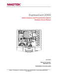
1
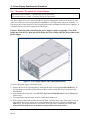
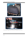
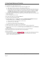
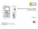
ExpressCard 2000 Instant Issuance Card Personalization System Power Supply Replacement Procedure September 22, 2014 Manual Part Number: 99875717-1.01 REGISTERED TO ISO 9001:2008 MagTek I 1710 Apollo Court I Seal Beach, CA 90740 I Phone: (562) 546-6400 I Technical Support: (888) 624-8350 www.magtek.com Copyright © 2006 - 2014 MagTek, Inc. Printed in the United States of America Information in this publication is subject to change without notice and may contain technical inaccuracies or graphical discrepancies. Changes or improvements made to this product will be updated in the next publication release. No part of this document may be reproduced or transmitted in any form or by any means, electronic or mechanical, for any purpose, without the express written permission of MagTek, Inc. MagTek® is a registered trademark of MagTek, Inc. MagnePrint® is a registered trademark of MagTek, Inc. Magensa™ is a trademark of MagTek, Inc. MagneSafe™ is a trademark of MagTek, Inc. ExpressCard 2000 is a trademark of MagTek, Inc. Microsoft® and Windows® are registered trademarks of Microsoft Corporation. All other system names and product names are the property of their respective owners. Table 0.1 - Revisions Rev Number 1.01 Date 09/22/2014 Notes Initial release derived from 99875607-5.01-DRAFT ExpressCard 2000| Instant Issuance Card Personalization System | Power Supply Replacement Procedure Page 2 SAFETY This product has been evaluated by multiple safety certification agencies, including Underwriters Laboratories (UL) and the United States Federal Communications Commission (FCC Class A and Class B), and is designed to protect both the user and the device. This document is written specifically to work in conjunction with these safety and integrity features to protect the user and the device. It is very important to follow all steps in the product documentation carefully, in the order in which they are described, and at the recommended times. Failure to do so could result in personal injury, and / or cause damage to the device, and / or void the product warranty. The information within this manual has been prepared for use by trained professional service personnel and is not intended for general use. To maintain the safety and integrity of the machine, follow the procedures described in this manual carefully. For your personal safety and to prevent damage to the device, disconnect power from the device before you connect or disconnect any cable, electronic board, or assembly. SAFETY REQUIREMENTS Caution: Never do any of the following: DO NOT use a ground adapter plug to connect equipment to a power socket-outlet that lacks a ground connection terminal. DO NOT attempt any maintenance function that is not specifically described in this manual or in other ExpressCard 2000 instructional documents published by MagTek. DO NOT override or “cheat” electrical or mechanical interlock devices. DO NOT use EC2000 supplies or cleaning materials for other than their intended purposes. DO NOT operate the equipment if you or anyone else have noticed unusual noises or odors. Consider the following before operating the ExpressCard 2000: Connect the EC2000 to a properly grounded AC power socket-outlet. If in doubt, have the socketoutlet checked by a qualified electrician. Improper connection of the device’s grounding conductor creates a risk of electric shock. Place the EC2000 on a solid surface that can safely support the device’s weight support the weight of the EC2000 PLUS the weight of a person leaning against the device (such as a service technician). Be careful when moving or relocating the device. Use proper lifting techniques. Use materials and supplies specifically designed for MagTek devices. Using unsuitable materials may result in poor performance, and in some cases may be hazardous. ExpressCard 2000| Instant Issuance Card Personalization System | Power Supply Replacement Procedure Page 3 1 - Table of Contents Table of Contents Table of Contents ............................................................................................................................... 4 1 Required Tools, Materials, and Documents ........................................................................... 5 1.1 Required Tools ..................................................................................................................... 5 1.2 Suggested Tools .................................................................................................................. 5 1.3 Required Materials ............................................................................................................. 5 1.4 Suggested Materials ........................................................................................................... 5 1.5 Required Software and Documents ................................................................................. 5 2 Introduction ................................................................................................................................. 6 3 Power Supply Replacement Procedure .................................................................................. 7 3.1 Prepare the Device ............................................................................................................. 7 3.2 Remove / Re-install the Power Supply ............................................................................ 8 ExpressCard 2000| Instant Issuance Card Personalization System | Power Supply Replacement Procedure Page 4 1 - Required Tools, Materials, and Documents 1 Required Tools, Materials, and Documents 1.1 Required Tools Part Number 33011008 1.2 Quantity 1 ea. Description ASM TOOL KIT,FIELD SERVICE,EC2000 Suggested Tools Part Number N/A 1.3 Quantity 1 ea. Description Flashlight Required Materials Part Number 33070941 1.4 Quantity 1 ea. Description ASM REPLACEMENT KIT,POWER SUPPLY,EC2000 Suggested Materials Part Number 33011009 1.5 Quantity 1 ea. Description ASM KIT,STARTER,SPARE,FIELD SERVICE,EC2000 Required Software and Documents MagTek recommends loading the following required software and documents on a USB thumb drive or service laptop before visiting the customer site. Part Number Quantity Description 99875600 1 ea. MNL USER INSTALL & OPERATION MANUAL,EC2000 99875607 1 ea. MNL HARDWARE SERVICE MANUAL,EC2000 ExpressCard 2000| Instant Issuance Card Personalization System | Power Supply Replacement Procedure Page 5 2 - Introduction 2 Introduction This procedure describes how to replace the power supply in the ExpressCard 2000 (EC2000), and is based on content in 99875607 ExpressCard 2000 Hardware Service Manual. It assumes the reader is familiar with basic operation of the ExpressCard 2000’s user and maintenance functions, so many of the cross-references to deeper “how-to” procedures from that manual have been removed for brevity. The information in this document is intended for use by trained professional service personnel only. It is not intended for general use. To maintain the safety and integrity of the device, it is important to follow the procedures laid out in this document as-written and in the order provided. CAUTION: For your personal safety, and to prevent damage to the device, disconnect power from the ExpressCard 2000 before you connect or disconnect any cable, electronic board, or assembly. ExpressCard 2000| Instant Issuance Card Personalization System | Power Supply Replacement Procedure Page 6 3 - Power Supply Replacement Procedure 3 Power Supply Replacement Procedure 3.1 Prepare the Device Prepare the device for service by following these steps: 1) Offer the customer the opportunity to remove any proprietary or security-sensitive consumables from the device, including card stock, image printer ribbons, indent cartridges, and tipper foils. Some consumables contain negative imprints of cardholder data and must be handled securely. 2) Make sure the device is powered on and connected to the network. 3) Open the top access door. 4) Inspect the device for any items that do not belong inside the cover, and remove them (examples include loose mechanical parts, cards, insect or animal leavings, or jewelry). 5) Power down the device. 6) Disconnect the device’s power and network cables and any security hardware. ExpressCard 2000| Instant Issuance Card Personalization System | Power Supply Replacement Procedure Page 7 3 - Power Supply Replacement Procedure 3.2 Remove / Re-install the Power Supply Approximate time to remove: 15 minutes plus any sub-procedures Approximate time to re-install: 15 minutes plus any sub-procedures The power supply receives AC power from the AC power cord plugged in to the rear of the device, and converts it to the power levels required by the embedded PC, mail logic board, and power controller. It also reports power status and receive power-up and power-down commands from the power controller. It is located in the rear left of the bottom deck of the device. Caution: Removing and re-installing the power supply requires two people: First, both people move the device, then one person keeps the device stable while the other removes the power supply. Figure 3-1 - Power Supply (FRONT LEFT VIEW FROM ABOVE) To remove the power supply, follow these steps: 1) Prepare the device for replacing parts by following the steps in section 3.1 Prepare the Device. At the end, the device should be powered down with all external cables and security hardware safely disconnected. 2) Open the left side access door. See 99875607 ExpressCard 2000 Hardware Service Manual for detailed steps. 3) Take appropriate steps to protect the work surface the EC2000 is on. 4) With a partner, safely and carefully move the EC2000’s left side off the edge of the surface it sits on, only until the four power supply screws on the bottom of the device are exposed (see Figure 3-2, Figure 3-3). Do not move the device any further off the edge than is absolutely necessary. One person MUST hold the device at all times to keep it stable on the work surface. ExpressCard 2000| Instant Issuance Card Personalization System | Power Supply Replacement Procedure Page 8 3 - Power Supply Replacement Procedure Figure 3-2 – One Person Keeps the Device Stable (LEFT VIEW) Figure 3-3 - Four Power Supply Screws Exposed (BOTTOM LEFT VIEW) 5) Locate the power supply on the rear left side of the device, behind the left side access door. ExpressCard 2000| Instant Issuance Card Personalization System | Power Supply Replacement Procedure Page 9 3 - Power Supply Replacement Procedure Figure 3-4 - Power Supply (LEFT SIDE VIEW) 6) Remove the clear plastic cover that protects the power supply inputs. 7) Use the No. 2 Philips screwdriver to loosen the screws that secure the three power input wires to the power supply, then disconnect the wires. Figure 3-5 - Power Supply Input Wires (LEFT VIEW) 8) Unplug the white plastic power supply control and monitoring connector shown in Figure 3-6. ExpressCard 2000| Instant Issuance Card Personalization System | Power Supply Replacement Procedure Page 10 3 - Power Supply Replacement Procedure Figure 3-6 – Power Supply Control and Monitoring Connector (LEFT VIEW) 9) Use the No. 2 Philips screwdriver to loosen the screws holding the power supply output cables, then disconnect the cables. See Figure 3-7. Figure 3-7 - Power Supply Output Cables (LEFT VIEW) 10) Use the No. 2 screwdriver to remove the four screws on the bottom of the device that hold the power supply in place (see Figure 3-3 on page 9). 11) Remove the power supply and set it aside. 12) If you are not immediately installing a replacement, with a partner, safely and carefully move the device back to a stable operating position. ExpressCard 2000| Instant Issuance Card Personalization System | Power Supply Replacement Procedure Page 11 3 - Power Supply Replacement Procedure To re-install the power supply, follow these steps: 1) If the device is no longer positioned for access to the power supply screws: a) Take appropriate steps to protect the work surface the EC2000 is on. b) With a partner, safely and carefully move the EC2000’s left side off the edge of the surface it sits on, only until the four power supply screws on the bottom of the device are exposed (see Figure 3-2, Figure 3-3). Do not move the device any further off the edge than is absolutely necessary. One person MUST hold the device at all times to keep it stable on the work surface. 2) Put the power supply back into the device and line up its screw holes with the four screw holes on the bottom of the device. 3) Screw in and tighten the four screws. 4) Re-connect the output wires according to Figure 3-7. 5) Plug in the control and monitoring cable. 6) Re-connect the input wires. Insert the spade connectors behind the plate behind the screws (not directly behind the screws). See Figure 3-5. The connections are as follows: a) The green ground wire goes nearest the rear of the device. b) The black wire goes in the middle. c) The white wire goes nearest the front of the device. 7) Snap the clear plastic cover in place to cover the input wires. 8) With a partner, safely and carefully move the device back to a stable operating position. 9) Replace the left side access door (see 99875607 ExpressCard 2000 Hardware Service Manual for detailed steps). 10) Perform any additional service that requires the device to be powered off and open. 11) Re-attach the power cable, network cable, and any security hardware. 12) Power up the device. 13) From the touchscreen, navigate to Menu > Samples , create a sample card, and make sure the device functions properly and the sample looks correct. If the device does not power up or function properly, contact MagTek Support Services. ExpressCard 2000| Instant Issuance Card Personalization System | Power Supply Replacement Procedure Page 12