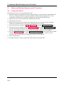
1
ExpressCard 2000 Instant Issuance Card Personalization System Embosser Module Replacement Procedure September 22, 2014 Manual Part Number: 99875705-1.01 REGISTERED TO ISO 9001:2008 MagTek I 1710 Apollo Court I Seal Beach, CA 90740 I Phone: (562) 546-6400 I Technical Support: (888) 624-8350 www.magtek.com Copyright © 2006 - 2014 MagTek, Inc. Printed in the United States of America Information in this publication is subject to change without notice and may contain technical inaccuracies or graphical discrepancies. Changes or improvements made to this product will be updated in the next publication release. No part of this document may be reproduced or transmitted in any form or by any means, electronic or mechanical, for any purpose, without the express written permission of MagTek, Inc. MagTek® is a registered trademark of MagTek, Inc. MagnePrint® is a registered trademark of MagTek, Inc. Magensa™ is a trademark of MagTek, Inc. MagneSafe™ is a trademark of MagTek, Inc. ExpressCard 2000 is a trademark of MagTek, Inc. Microsoft® and Windows® are registered trademarks of Microsoft Corporation. All other system names and product names are the property of their respective owners. Table 0.1 - Revisions Rev Number 1.01 Date 09/22/2014 Notes Initial release derived from 99875607-5.01-DRAFT ExpressCard 2000| Instant Issuance Card Personalization System | Embosser Module Replacement Procedure Page 2 SAFETY This product has been evaluated by multiple safety certification agencies, including Underwriters Laboratories (UL) and the United States Federal Communications Commission (FCC Class A and Class B), and is designed to protect both the user and the device. This document is written specifically to work in conjunction with these safety and integrity features to protect the user and the device. It is very important to follow all steps in the product documentation carefully, in the order in which they are described, and at the recommended times. Failure to do so could result in personal injury, and / or cause damage to the device, and / or void the product warranty. The information within this manual has been prepared for use by trained professional service personnel and is not intended for general use. To maintain the safety and integrity of the machine, follow the procedures described in this manual carefully. For your personal safety and to prevent damage to the device, disconnect power from the device before you connect or disconnect any cable, electronic board, or assembly. SAFETY REQUIREMENTS Caution: Never do any of the following: DO NOT use a ground adapter plug to connect equipment to a power socket-outlet that lacks a ground connection terminal. DO NOT attempt any maintenance function that is not specifically described in this manual or in other ExpressCard 2000 instructional documents published by MagTek. DO NOT override or “cheat” electrical or mechanical interlock devices. DO NOT use EC2000 supplies or cleaning materials for other than their intended purposes. DO NOT operate the equipment if you or anyone else have noticed unusual noises or odors. Consider the following before operating the ExpressCard 2000: Connect the EC2000 to a properly grounded AC power socket-outlet. If in doubt, have the socketoutlet checked by a qualified electrician. Improper connection of the device’s grounding conductor creates a risk of electric shock. Place the EC2000 on a solid surface that can safely support the device’s weight support the weight of the EC2000 PLUS the weight of a person leaning against the device (such as a service technician). Be careful when moving or relocating the device. Use proper lifting techniques. Use materials and supplies specifically designed for MagTek devices. Using unsuitable materials may result in poor performance, and in some cases may be hazardous. ExpressCard 2000| Instant Issuance Card Personalization System | Embosser Module Replacement Procedure Page 3 1 - Table of Contents Table of Contents Table of Contents ............................................................................................................................... 4 1 Required Tools, Materials, and Documents ........................................................................... 5 1.1 Required Tools ..................................................................................................................... 5 1.2 Suggested Tools .................................................................................................................. 5 1.3 Required Materials ............................................................................................................. 5 1.4 Suggested Materials ........................................................................................................... 5 1.5 Required Software and Documents ................................................................................. 5 2 Introduction ................................................................................................................................. 6 3 Embosser Module Replacement Procedure ........................................................................... 7 3.1 Prepare the Device ............................................................................................................. 7 3.2 Remove / Re-install the Embosser Module .................................................................... 8 3.3 How to Remove / Re-install Embosser Fonts ............................................................... 14 3.4 How to Use the Character Mapping Page ..................................................................... 15 3.5 How to Calibrate the Embosser Module ........................................................................ 17 3.6 How to Calibrate the Indenter Module ........................................................................... 22 ExpressCard 2000| Instant Issuance Card Personalization System | Embosser Module Replacement Procedure Page 4 1 - Required Tools, Materials, and Documents 1 Required Tools, Materials, and Documents 1.1 Required Tools Part Number Quantity Description 33011008 1 ea. ASM TOOL KIT,FIELD SERVICE,EC2000 N/A 1 ea. X-Acto knife (if removing embosser characters) N/A 1 ea. Micrometer or digital calipers (if calibrating embosser) 1.2 Suggested Tools Part Number N/A 1.3 Quantity 1 ea. Description Flashlight Required Materials Part Number 33070934 or 33070936 1.4 Quantity 1 ea. Description ASM REPLACEMENT KIT,EMBOSSER W REAR IND MOD,EC2000 or ASM REPLACEMNT KIT,EMBOSSER FRNT/REAR IND MOD,EC2K Suggested Materials Part Number 33011009 1.5 Quantity 1 ea. Description ASM KIT,STARTER,SPARE,FIELD SERVICE,EC2000 Required Software and Documents MagTek recommends loading the following required software and documents on a USB thumb drive or service laptop before visiting the customer site. Part Number Quantity Description 99875600 1 ea. MNL USER INSTALL & OPERATION MANUAL,EC2000 99875607 1 ea. MNL HARDWARE SERVICE MANUAL,EC2000 ExpressCard 2000| Instant Issuance Card Personalization System | Embosser Module Replacement Procedure Page 5 2 - Introduction 2 Introduction This procedure describes how to replace the embosser module in the ExpressCard 2000 (EC2000), and is based on content in 99875607 ExpressCard 2000 Hardware Service Manual. It assumes the reader is familiar with basic operation of the ExpressCard 2000’s user and maintenance functions, so many of the cross-references to deeper “how-to” procedures from that manual have been removed for brevity. The information in this document is intended for use by trained professional service personnel only. It is not intended for general use. To maintain the safety and integrity of the device, it is important to follow the procedures laid out in this document as-written and in the order provided. CAUTION: For your personal safety, and to prevent damage to the device, disconnect power from the ExpressCard 2000 before you connect or disconnect any cable, electronic board, or assembly. ExpressCard 2000| Instant Issuance Card Personalization System | Embosser Module Replacement Procedure Page 6 3 - Embosser Module Replacement Procedure 3 Embosser Module Replacement Procedure 3.1 Prepare the Device Prepare the device for service by following these steps: 1) Offer the customer the opportunity to remove any proprietary or security-sensitive consumables from the device, including card stock, image printer ribbons, indent cartridges, and tipper foils. Some consumables contain negative imprints of cardholder data and must be handled securely. 2) Make sure the device is powered on and connected to the network. 3) Open the top access door. 4) Inspect the device for any items that do not belong inside the cover, and remove them (examples include loose mechanical parts, cards, insect or animal leavings, or jewelry). 5) From the touchscreen, navigate to Menu > Maintenance to open the Maintenance Menu page. 6) If the device has a top indenter, press the Unload Cartridge button under Top Indent Cartridge to move the front indent cartridge into the unload position. Remove the top indent cartridge and set it aside in a secure location or give it to the customer for temporary storage or secure disposal. 7) Press the Unload Cartridge button in the Bottom Indent Cartridge section to move the rear indent cartridge into the unload position. Remove the rear indent cartridge and set it aside in a secure location, or give it to the customer for temporary storage or secure disposal. 8) Power down the device. 9) Disconnect the device’s power and network cables and any security hardware. ExpressCard 2000| Instant Issuance Card Personalization System | Embosser Module Replacement Procedure Page 7 3 - Embosser Module Replacement Procedure 3.2 Remove / Re-install the Embosser Module Approximate time to remove: 15 minutes plus any sub-procedures Approximate time to re-install: 30 minutes plus any sub-procedures The embosser module, located at the front left corner of the device, punches raised and indented characters into cards as they are held by the XY transport. Figure 3-1 - Embosser Module (FRONT RIGHT VIEW) To remove the embosser module, follow these steps: 1) Remove the cover (see 99875607 ExpressCard 2000 Hardware Service Manual for details). 2) Carefully disconnect the embosser’s cable from the top deck, making sure not to break any wires. Figure 3-2 shows the cable as seen from the left side of the device. ExpressCard 2000| Instant Issuance Card Personalization System | Embosser Module Replacement Procedure Page 8 3 - Embosser Module Replacement Procedure Figure 3-2 - Embosser Cable (TOP VIEW FROM LEFT) 3) Re-route the embosser cable so the connector rests on top of the XY transport rails, as shown in Figure 3-3. Figure 3-3 - Safe Removal Position for Embosser Cable (TOP VIEW FROM LEFT) 4) In each of the following steps, rotate the embosser daisy wheel so only empty tines are near the Allen wrench. This saves time if the wrench slips and breaks a tine; if the broken tine were not empty, you would have to re-install the font to another tine and re-map it in the software. 5) Use the 5/32” ball-end Allen wrench to remove the three screws that attach the rear indent module to the embosser. The left image in Figure 3-4 shows two screws as seen from the left side of the device, and the right image shows the final screw as seen from the rear of the device. ExpressCard 2000| Instant Issuance Card Personalization System | Embosser Module Replacement Procedure Page 9 3 - Embosser Module Replacement Procedure Figure 3-4 - Unfastening Rear Indent Module (TOP VIEW FROM LEFT and TOP VIEW FROM REAR) 6) Use the 5/32” ball-end Allen wrench to remove the four screws and washers that attach the embosser to the top deck plate, and set them aside. The left image in Figure 3-5 shows two screws as seen from the front of the device, and the right image shows the other two as seen from the rear of the device. Figure 3-5 - Unfastening Embosser (TOP VIEW FROM FRONT and TOP VIEW FROM REAR) 7) Use both hands to lift the embosser and indenter modules out of the device, making sure the embosser cable does not catch on anything on the way out. Set the modules aside. ExpressCard 2000| Instant Issuance Card Personalization System | Embosser Module Replacement Procedure Page 10 3 - Embosser Module Replacement Procedure To re-install the embosser module, follow these steps: 1) Use both hands to lower the replacement embosser and indenter modules (already together) into the device in the same position and orientation as the one you just removed. Line up the four corner screw holes in the embosser with the four corresponding screw holes in the top deck plate. 2) Make sure the two raised keys stamped into the top deck plate (see Figure 3-6) are seated in the indentations in the base of the embosser. Push the embosser forward, backward, left, and right to make sure they are holding the embosser in place. Figure 3-6 - Embosser Base Keys In Top Deck Plate (TOP RIGHT VIEW) 3) Use the 5/32” ball-end Allen wrench to re-fasten and tighten the four screws and washers that attach the corners of the embosser to the top deck plate. ExpressCard 2000| Instant Issuance Card Personalization System | Embosser Module Replacement Procedure Page 11 3 - Embosser Module Replacement Procedure 4) Line up the three screw holes in the indenter module with the three screw holes in the embosser module and the top deck plate. Use the 5/32” ball-end Allen wrench to re-fasten the three screws that attach the indenter module to the embosser module. 5) Route the embosser cable along the left wall of the device, then under the XY transport belt and rails as shown in Figure 3-2. 6) Plug the embosser cable back in to its connector on the top deck plate. Press firmly on the two metal sides of the connector to make sure it is seated tightly. 7) Perform any additional service that requires the device to be powered off and open. 8) Re-install the cover and top access door (see 99875607 ExpressCard 2000 Hardware Service Manual for details). 9) Re-attach the power cable and network cable, and power on the device. 10) Use the tools found in Menu > Maintenance to re-install any indent cartridges you removed at the beginning of these steps. Install the original cartridges or obtain new ones from the customer. 11) If you have installed a new embosser with all characters in factory-default locations, and if the customer has no custom characters installed, wait until other service is complete and the device is ready to power up, then reset the character mappings in the touchscreen software as follows: a) From the touchscreen, navigate to Menu > Settings > Service > Wheel Map to open the first Wheel Mapping password page. b) Enter password 4567890 and press the E key to open the second Wheel Mapping password page. c) Enter password 0987654 and press the E key to open the Wheel Mapping page. d) Press the Reset button. 12) If the original embosser had custom characters installed, carry them over to the same locations on the new embosser’s daisy wheel by following the steps in section 3.3 How to Remove / Re-install Embosser Fonts and section 3.4 How to Use the Character Mapping Page. 13) Calibrate the embosser using the information in section 3.5 How to Calibrate the Embosser Module. 14) Calibrate the indenter using the information in section 3.6 How to Calibrate the Indenter Module. 15) Test the device, paying special attention to the following: ExpressCard 2000| Instant Issuance Card Personalization System | Embosser Module Replacement Procedure Page 12 3 - Embosser Module Replacement Procedure a) Navigate to Menu > Settings > Tuning to open the Tuning (Move Embossing) page. b) Make sure the ribbon information in the upper left corner matches the ribbon you are using. If it doesn’t, set and calibrate the ribbon (see the ExpressCard 2000 User Installation and Operation Manual for details). c) Press the Print button. The EC2000 will create a test card with all characters and all font IDs. d) Inspect the card to make sure the embosser is working as expected. 16) If the EC2000 does not power up or function properly, contact MagTek Support Services. ExpressCard 2000| Instant Issuance Card Personalization System | Embosser Module Replacement Procedure Page 13 3 - Embosser Module Replacement Procedure 3.3 How to Remove / Re-install Embosser Fonts Under normal circumstances, the characters on the embosser module’s daisy wheel do not need to be removed. Embosser characters should be removed and replaced as little as possible, because removal causes the tine to wear and eventually become less effective at holding characters. If a tine breaks, however, it may be necessary to move its character to a new tine. Figure 3-7 - Removing a Character from the Embosser Module Daisy Wheel To remove a character from a tine on the embosser module’s daisy wheel, follow these steps: 1) Insert an X-Acto knife between the tine and the character as shown in Figure 3-7. 2) Carefully pry the character toward the ceiling until you can remove it with your fingers. 3) Prepare the character for installation in the new time by making sure it is oriented correctly. 4) Support the tine, then press the character into place with your fingers. 5) Notify the EC2000’s software that the character has moved. For detailed instructions, refer to section 3.4 How to Use the Character Mapping Page. ExpressCard 2000| Instant Issuance Card Personalization System | Embosser Module Replacement Procedure Page 14 3 - Embosser Module Replacement Procedure 3.4 How to Use the Character Mapping Page The Character Mapping page provides support for changing the configuration of characters on the EC2000 embosser’s daisy wheel. Functions include adding new fonts, moving an existing character to a different tine, and removing a character from a tine. At any time (such as if you make a mistake that you discover later in testing), you can reset the changes you made to the daisy wheel and return them to factory defaults by navigating to Menu > Settings > Service > Wheel Map and pressing the Reset button. To move a character from one daisy wheel tine to another, follow these steps: 1) Look at the numbers stamped on each daisy wheel tine to determine which tine the character was (or is) originally on, and which tine you will move it to. 2) If the character is still on the old tine, uninstall it. Every character has a piece on the top daisy wheel and a second piece on the bottom daisy wheel, so make sure to uninstall both, and to note which piece belongs on the top and which piece belongs on the bottom. 3) Install both halves of the character on the new tine. 4) From the touchscreen, navigate to Menu > Settings > Service > Char Map to open the first Character Mapping password page. 5) Enter password 4567890 , then press the E key to open the second Character Mapping password page. 6) Enter password 0987654 , then press the E key to open the Character Mapping page. 7) Use the From Current dropdown list to select the old tine where the character was installed. 8) Use the To New Tine dropdown list to select the new tine where the character is now installed. 9) Press the Move button. 10) Repeat the above steps for any additional characters you need to move. 11) Test your changes by creating a sample card or an embosser tuning card. To remove a character from a daisy wheel tine, follow these steps: 1) Look at the numbers stamped on each daisy wheel tine to determine which tine you want to remove the character from. 2) If the character is still on the old tine, uninstall it. Every character has a piece on the top daisy wheel and a second piece on the bottom daisy wheel, so make sure to uninstall both. 3) From the touchscreen, navigate to Menu > Settings > Service > Char Map to open the first Character Mapping password page. 4) Enter password 4567890 , then press the E key to open the second Character Mapping password page. 5) Enter password 0987654 , then press the E key to open the Character Mapping page. 6) Use the From Current Tine dropdown list to select the tine where the character was installed. 7) Press the Clear button. 8) Repeat the above steps for any additional characters you need to remove. 9) Test your changes by creating a sample card or an embosser tuning card. To add a new character to a daisy wheel tine, follow these steps: 1) Verify the EC2000 software supports the character(s) you are going to install. ExpressCard 2000| Instant Issuance Card Personalization System | Embosser Module Replacement Procedure Page 15 3 - Embosser Module Replacement Procedure 2) Look at the numbers stamped on each daisy wheel tine to find the number of the tine where you will install the new character. 3) Install the character on the tine. Every character has a piece on the top daisy wheel and a second piece on the bottom daisy wheel, so make sure to install both, and to put each piece on the correct half: For embossing fonts and rear indent fonts (FontID1, FontID2, and FontID4), the “punch” (positive) side goes on the bottom; for front indent fonts (FontID3), the “punch” side goes on the top. Indent fonts have a “blank” flat side that goes opposite the punch side. 4) Install both halves of the character on the new tine. 5) From the touchscreen, navigate to Menu > Settings > Service > Char Map to open the first Character Mapping password page. 6) Enter password 4567890 , then press the E key to open the second Character Mapping password page. 7) Enter password 0987654 , then press the E key to open the Character Mapping page. 8) Use the Add Char. dropdown list to select what character you are installing (for example, if you are installing a capital ‘A,’ select 65). Verify you have selected the character you expected to select by looking at the ASCII Char box next to the dropdown list. 9) Use the Font dropdown list to indicate the type of font you have installed (FontID1-4). 10) Use the To dropdown list to select which tine you have installed the characters on. 11) Press the Add button. 12) Repeat the above steps for any additional characters you need to add. 13) Test your changes by creating a sample card or an embosser tuning card. ExpressCard 2000| Instant Issuance Card Personalization System | Embosser Module Replacement Procedure Page 16 3 - Embosser Module Replacement Procedure 3.5 How to Calibrate the Embosser Module 3.5.1 About Embosser Calibration The EC2000 embosser squeezes cards between two “knuckles.” Each knuckle can be adjusted higher or lower to make sure embossed characters are being pressed deeply enough into the card, and to make sure the card is being squeezed evenly on both sides (see Figure 3-8). Figure 3-8 –Embosser Knuckles (REAR LEFT VIEW and PROFILE VIEW) Each knuckle can be rotated to point one of its six faces toward the card being embossed. Each face presses to a different depth. +3 is the highest pressure setting, and -3 is the lowest pressure setting. You can read the current depth by looking at the shape carved into the side of the knuckle that faces the card (see Figure 3-9). Figure 3-9 - Embosser Knuckle Heights Key (+3 = Most Pressure, -3 = Least Pressure) ExpressCard 2000| Instant Issuance Card Personalization System | Embosser Module Replacement Procedure Page 17 3 - Embosser Module Replacement Procedure 3.5.2 Check Knuckle Position The replacement embosser should have ink marks indicating factory-calibrated positions for the top and bottom knuckle. Make sure the inked portions line up with each other as shown in Figure 3-10. Figure 3-10 - Marking Factory Default Knuckle Position (REAR VIEW) ExpressCard 2000| Instant Issuance Card Personalization System | Embosser Module Replacement Procedure Page 18 3 - Embosser Module Replacement Procedure 3.5.3 Calibrate the Embosser Wheel Home Position To make sure the motor controller accurately centers the embosser wheel in the embosser bridge opening, follow these steps: 1) Close the EC2000 top access door to make sure no light will interfere with the sensor. 2) In the ExpressCard 2000 Utility, Navigate to Menu > Settings > Service > MCP Commands to open the Controller Commands page. 3) Press Calibrate Wheel Home button and wait for 10 seconds until the embosser stops moving. The system will fill in a value below Calibrate Wheel Home . 4) Repeat the Calibrate Wheel Home operation several times until you see the same number three times in a row. If the number continues to change after 10 tests, report the unit’s failure to calibrate. 5) Check that the value below Calibrate Wheel Home is between 4 and 10. If the value is not in that range, report the unit’s failure to calibrate within the acceptable range. ExpressCard 2000| Instant Issuance Card Personalization System | Embosser Module Replacement Procedure Page 19 3 - Embosser Module Replacement Procedure 6) After successfully calibrating, press the Save button to save the new embosser wheel center value. 7) Press the OK button to dismiss the popup window confirming it has been saved. 8) Open the top access door and inspect the embosser tine position to make sure the currently selected tine is centered in the embosser bridge opening. 9) Press the Status button to return to the Status page. ExpressCard 2000| Instant Issuance Card Personalization System | Embosser Module Replacement Procedure Page 20 3 - Embosser Module Replacement Procedure 3.5.4 Set Embossed Character Height Using Software Using the numbers on the label on the replacement embosser’s base, set the cam angle settings by following these steps: 1) Locate the factory default knuckle and Cam Angle settings on the base of the embosser, as shown in Figure 3-11. Figure 3-11 - Factory Default Knuckle and CamAngle Settings (TOP VIEW FROM FRONT) 2) In the ExpressCard 2000 Utility, navigate to Menu > Settings > Edit Config to open the Configuration Editing password page. 3) Use the onscreen keypad to enter password 1234567 and press the E key. 4) Use the onscreen keypad to enter password 7654321 and press the E key. 5) Scroll through the settings list to find CamAngleTop and CamAngleBottom. 6) Select FontID1 > CamAngleTop, enter the new value in the text entry box at the top right of the screen, and press the E key. 7) Otherwise, select FontID1 > CamAngleBottom, enter the new value in the text entry box at the top right of the screen, and press the E key. 8) Repeat the process for FontID2 and any other fonts shown on the embosser base. 9) Press the Save button to save the new settings. ExpressCard 2000| Instant Issuance Card Personalization System | Embosser Module Replacement Procedure Page 21 3 - Embosser Module Replacement Procedure 3.6 How to Calibrate the Indenter Module 3.6.1 About Calibrating the Indenter Module The rear indenter module in the EC2000’s embosser moves between three positions: LOAD position: During normal operation, it is “parked” below the embosser. HOME position: During rear indent operations, it moves out of the embosser and places the ribbon between the characters on the embosser wheel. UNLOAD position: When removing the indent cartridge, it moves all the way out for easy removal. If the indent ribbons are aligned such that indented characters are too far toward one edge of the indent ribbon, follow the steps in this section to re-align the indenter. 3.6.2 Calibrate the Rear Indent Cartridge Positions To calibrate the indent position of the indenter, follow these steps: 1) Create a sample card using sample 3 in Menu > Samples . 2) Navigate to Menu > Settings > Service > MCP Cmds to open the Controller Commands page. 3) Under the “Indenter Move” button, select Bot Cartridge Unload in the dropdown list. 4) Press the Indenter Move button. The device will move the indenter to the unload position. ExpressCard 2000| Instant Issuance Card Personalization System | Embosser Module Replacement Procedure Page 22 3 - Embosser Module Replacement Procedure 5) Look at the up-down position of the negative letters or numbers (removed ink) on the indenter ribbon. They should be centered between the top edge and bottom edge of the ribbon. 6) If they are not centered: a) Navigate to Menu > Settings > Edit Config to open the Configuration Editing password page. b) Enter password 1234567 and press the E button. c) Enter password 7654321 and press the E button. d) Scroll down in the list and select the number below the BotCardTridgeHomeToIndent item. e) Press the C button to clear the current value. f) If the letters were too far to the rear of the EC2000, enter a larger number for BotCardTridgeHomeToIndent. You probably only need to change by 1-5 steps. ExpressCard 2000| Instant Issuance Card Personalization System | Embosser Module Replacement Procedure Page 23 3 - Embosser Module Replacement Procedure g) If the letters were too far to the front of the EC2000, enter a smaller number for BotCardTridgeHomeToIndent. You probably only need to change by 1-5 steps. h) Press the E button to finish entering the new value. i) Press the Save button to save your changes. The system will report “The modified configuration has been saved.” Press OK to close the popup window. 7) Navigate to Menu > Settings > Service > MCP Cmds to open the Controller Commands page. 8) Under the “Indenter Move” button, select Bot Cartridge Load in the dropdown list. 9) Press the Indenter Move button. The device will move the indenter to the load position. 10) Repeat the steps in this section until the negative letters or numbers on the rear indent cartridge are centered between the top and bottom edge. ExpressCard 2000| Instant Issuance Card Personalization System | Embosser Module Replacement Procedure Page 24 3 - Embosser Module Replacement Procedure 3.6.3 Calibrate the Front Indent Cartridge Positions If the device you are calibrating has a front indent ribbon cartridge (which has white ribbon and mounts above the embosser), follow the steps from section 3.6.2 Calibrate the Rear Indent Cartridge Positions, with the following modifications: Everywhere the steps specify “Bottom” or “Bot,” read as “Top.” Everywhere the steps specify “Rear,” read as “Front.” ExpressCard 2000| Instant Issuance Card Personalization System | Embosser Module Replacement Procedure Page 25