1
Vol. 6
Number 10
The
RADIO CONSTRUCTOR
JUNE
1953
BOOKS
FOR
THE
TV
ENTHUSIAST
B&DOO
i
FAULT FINDING
;
.
1
"mg ' i
isasi
: ,j.
■
BBEBSHHSBHNHHHHflHHHBHEBBIINHiiB
■1^.
rra«ui*rv
UluicpiiiM witii
rraluterv
WIW
plMl*srkf«u CsJIkM lr«m
Aimlprrnt^d Short Wive PrWf Ltd
"... A book that should be in
every television dealers service
workshop, and in every homeconstructor's, for that matter."
Journal of the Television Society
"... The book will undoubtedly
be of value to TV service engineers, particularly those who are
not fully experienced in translating
the appearance of faulty pictures
into the necessary adjustments or
receiver fault location."
Wireless and Electrical Trader
Hudio
and
Telerision
Tnihasiast
K
TELEVISION
PICTURE FAULTS
n
T^E^jsTON
JUNE
1955
Postoge 2d.
Both books available from your
usual supplier, or direct
(Trade enquiries invited)
DATA
the
Postage 3d.
68 poges, size Ji" x 5"
Price 3s. 6d.
for
Lavishly illustrated by photographs
taken from the screen of a televisor exhibiting the faults under
discussion.
80 pages, size 8i" x Si"
Price 5s.
Edited by John Cura and Leonard
Stanley, and illustrated with ISO
"Tele-Snaps," this book caters
for both the home viewer, and
the more advanced constructor.
We regard both these books as
complementary, and have no hesitation in recommending them to
all television servicemen and constructors.
GonomcraTfOB
PUBLICATIONS
SERVICE
ALSO in this issue
N !|Mr
" f*PiAVAmws
roit tut
vkwk 11
■
liCHMUl
WUHATitWlS
FOR komi
tN( fXPlBl
^3
57 Maida Vale London W9
Published by Data Publications (Amalgamated Short Wave Press Ltd.) 57 Maida Vale Paddington
London W9 Printed by A. Quick and Company Limited Oxford House Clacton-on-Sea Essex www.americanradiohistory.com
Mil
THE "UNIVERSAL" LARGE SCREEN AC/DC
TELEVISOR
"BASS-LIFT FOUR" RECEIVER
SIMPLE AC/DC AMPLIFIER
MAGNETIC RECORDING EQUALISATION
Accurate Null Indicator ' Radio Control Equipment
AF Pre-Amplifier • Query Corner etc. etc.
RADIO CONSTRUCTOR
RADIO CONSTRUCTOR
THE
MODERN
Sound Reproduction by G. A Briggs.
3rd edn. 17s 6d. Postage 6d.
Amplifier Circuits by N. H, Crowhurst. Is 6d. Postage Id.
Radio Engineers' Servicing Manual,
edited by E. Molioy. 42s Od. Postage Is Od.
Personal Receivers by E. N. Bradley.
3s 6d. Postoge 2d.
Radio Interference Suppression by
G. L Stephens. 10s 6d. Postage 4d.
Television Engineers' Servicing
Manual edited by E, Molloy. 42s. Od.
Postage Is Od.
The Use of a.f. Transformers by
N. H. Crowhurst. 3s 6d. Postage 2d.
BOOK CO.
TV Fault Finding compiled by The
Radio Constructor. 5s Od. Postage 4d.
The Radio Amateur Operator's
Handbook compiled by the Staff of
The Radio Amateur. 2s 6d. Postage 2d.
inexpensive Television for the Home
Constructor. 2s 6d. Postage 2d.
Television Receiver Practice by
R. Holland. Ss Od. Postage 3d.
The Amateur's Guide to Valve
Selection by Mullard. Is 6d. Postage 2d.
Radio Valve Data compiled by
Wire/ess World. 3s 6d. Postage 3d.
The Radio Amateur's Handbook by
the A.R..R..L. 1953. 30s Od. Post
oge Is Od.
ST
Did you build your own T/V receiver?
We have the finest selection of British and American Radio
Books in the Country.
Complete list on application.
19-23 PRAED STREET (Dept. RC) LONDON W2
PADdington 4i85
SCOTTISH
INSURANCE
CORPORATION
LTD
497
62-63
CHEAPSIDE
LONDON,
E.C.2.
TELEVfSION SETS AND SHORT WAVE TRANSMITTERS
Televition Sets and Short Wave Transmitters/Receivers are expensive to acquire and you no
doubt highly prize your installation. Apart from the value of your Set, you might be held resp-snsibie should injury be caused by a fault in the Set, or Injury or damage by your Aerial coiiapsing.
A "Scottish" special policy for Television Sets and Short Wave Transmitters Receivers
provides the following cover:—
(q). Loss pr daiinage to installation (including in the case of Television Sets the Cathode Rav
Tube) by iiife. Explosion, Lightning, Theft or Accidental External Means at any private
dwelling house.
(b) (i) Legal Liability for bodily injury to Third Parties or damage to their property arising
out of the breakage or collapse of the Aerial Fittings or Mast, or through any defect
in the Set. Indemnity £10,000 any one accident.
(il) Damage to your property or that of your landlord arising out of the breakage or
collapse of the Aerial Fittings or Mast, but not exceeding £500.
The cost of Cover (a) is 5/— a year for Sets worth £50 or less, and for Sets valued at more
than £50 the cost is in proportion. Cover (b) (i) and (ii) costs only 2/6d a year if taken with
Cover (a), or 5/- if taken alone.
Why not BE PRUDENT AND INSURE your installation—it is well worth while AT THE
VERY LOW COST INVOLVED. If you will complete and return this form to the Corporation's
Office at the above address, a proposal will be submitted for completion.
NAME (Block Letters)
(If Lody, state Mrs. or Miss)
ADDRESS (block Letters)
./JB
If so, and you have a 9" or 12" set and
now want to convert to big-screen
viewing3 how better than by using an
'English Electric' 16" T901 Metal
C.R, tube.
To help you carry out the work our
leaflet EV103A gives you the complete
line and frame scanning information
necessary, together with a suggested list
of required components.
And why a T901 — because it offers
you brilliance, long life, high safety
ENGLISH
factor, ease of handling and withal it is
British made.
It is the tube specified by the designers of the'Tele-King' and 'Magnaview'
circuits and 'Viewmaster' conversion
circuit.
Brilliant black and white picture
focussing over entire screen area with
excellent contrast range; high optical
quality glass face plate; wide angle
scanning (jOa); fitted ion trap; overall
length 17H", diameter 16".
ELECTRIC
BRITISH HADE LONG LIFE METAL C.R. TUBE
If you have any difficulty in obtaining supplies write to:
The ENGLISH ELECTRIC Co. Ltd., Television Department, Queens House, Kings way, London, W.C.2.
www.americanradiohistory.com
498
499
RADIO CONSTRUCTOR
RADIO CONSTRUCTOR
Recognised as the Most Reliable Valveholders
WIDE
A NGL E
TV
bt
^ED:G^RE?R:0AD
Ailen, Denco, Colvern
Dubilier, Elac, McMurdo, Morgan
STC, TCC
for the
"TELEKING"
"VIEWMASTER" CONVERSION
and "MAGNA VIEW"
(Radio Constructor)
also
TUBES, VALVES & CABINETS
etc»
Price Lists on receipt of SAE
H. L. SMITH & CO. LTD.
287/9 Edgware Road London W2
Telephone Paddingcon 5891
Hours 9 till 6 (Thursday I o'clock)
Nr. Edgware Road Stations, Metropolitan A Bakerloo
ARTHURS HAVE ITt
LONDON'S OLDEST RADIO DEALERS
LARGE VALVE STOCKS
AVOMETERS IN STOCK
Avo Test Meters and Signal Generators
and Taylor Meters
Leak Point One Amplifiers and Tuning
Units.
Chapman Tuning Units.
Crystal and Moving Coil Mies.
Decca Replacement Heads and Pickups,
Goodman's Axiom ISO Speakers.
Partridge Output Transformers for Williamson Amplifier.
All Components for the Radio Constructor's
16" Televisor.
Weare & Wright Tape Deck £35.
LATEST VALVE MANUALS
Mullard, Osram & Brimar No. 4 5/- each
Mazda 2/- each
Postage 6d. extra
TELEVISION! SETS, WIRE AND TAPE
RECORDERS ALWAYS IN STOCK
Goods offered subject to price alterations
and being unsold.
Est.
1919
Arthurs
first
PROP: ARTHUR GRAY LTD.
OUR ONLY ADDRESS: Gray House
150-52 Charing Cross Road
London, W.C.2.
TEMple Bar 583314 and 4765 WRITE FOR LISTS
B8A
y*
Kb
o
O/nf
r:-
S
B9A
For
B7G
SUCCESSFUL
wide-angle
TELEVISION
scanning
CABINETS
ALLEN
COMPONENTS LIMITED
Crown Works 197 Lower Richmond Rd
Richmond Surrey
Telephone Prospect 9013
the Market
—-specially chosen for the Magna-Vie^v
All Sizes up to 16* Tube
ALLEN DEFLECTOR COILS
70° Scan with minimum deflection
defocusing High-efficiency castellated
"FERROXCUBE" core. Suits any wide
angle C.R.T. up to 27" double (d) Scan.
LARGE SCREEN TELEVISION
Can only be achieved by using high
efficiency components throughout.
ALLEN can supply the complete range.
For jjrices and details of fcr
ne circuit diagram of
, full
- range of ALLEN ''send
cd and
Timestamped
Base
the
9d,
components—Write to addressed envelope to
The Best Valveholders on
Specially Designed for 'Radio Constructor' Set, and Illustrated on the
September Front Cover
Price £18:10 Carriage £1
Home
TYPES
SEND FOR ILLUSTRATED LEAFLET
H. ASHDOWN
98 HERTFORD ROAD
TOT 2621
EDMONTON N9
Constructor's Television Set
I B7G
B9A
■
■
I International Octal
BMTjU and XM7j U.
BM9/ U, X;\t9lVand BM9:UB.
BSjU and X8.4', JJ.
Wholesale Enquiries: — CYRIL FRENCH LTD., HIGH STREET, HAMPTON WICK.
MIDDLESEX • KINGSTON 2240
/danufacturers' Enquir es:—THE McMURDO INSTRUMENT CO., LTD.. VICTORIA WORKS.
A5HTEAD, SURREY • ASHTEAD 3401
www.americanradiohistory.com
500
RADIO CONSTRUCTOR
Your
The
Radio
Constructor
Vol. 6. No. 10.
Annual Subscription 18/June 1953
Editoral and Advertising Offices—57 Maida Vale Paddington
Telephone CUNingham 6518
London W9
Edited by C. W. C. OVERLAND, G2ATV
set
deserves a
w:
CONTENTS
Milliard
Suggested Circuits: An Accurate Null Indicator, by G. A. French
In Your Workshop, by J. R. D
Valves and Their Power Supplies, Part 7, by F, L. Bayliss, A.M.I.E.T
Magnetic Recording Equalisation—With Some Amplifier
Modifications, by L. F. Sinfield, A.M.LP.R.E
Book Review
" Bass-Lift Four " for AC Mains, by A. Carpenter
Trade Review
.
Radio Control Equipment, Part 4, by Raymond F. Stock
Radio Miscellany, by Centre Tap
The " Universal " Large Screen AC/DC Televisor, described by
A. S. Torrance, A.M.LP.R.E., A.M.T.S
Astigmatism in Electrostatic Cathode Ray Tubes, by C. R. Drayton
Audio Pre-Amplifiers, Part 3, by D. Nappin
A Simple AC/DC Amplifier, by James. S. Kendall, Assoc.Brit.I.R.E.
M.I.P.R.E
Let's Get Started—(2) Quart from a Pint Pot, by A. Blackburn
Query Corner—A Radio Constructor Service for Readers
Radio Components Exhibition 1953, Visited by L, A. Chinnery, G3iIZ
From Our Mailbag
Some Useful Hints, by J. S. K. .
.
.
,
yDINIChUIFi
TV TUBE
if you are building a television
receiver, leave nothing to chance;
choose a Milliard Tube, Mullard
Television Tubes owe their high
reputation for performance, reliability and LONG- LIFE to the
unrivalled facilities for research
possessed by Mullard; to the complete control of manufacture from
the production of raw materials to the co mpleted product;
and, in particular, to the iontrap, which safeguards the
screen from damage by heavynegative ions produced in the
region of the cathode.
• 'oo lube,
IT- '- mi*. ' 3
Ipli
SU-M---1s3 screen.
„
"h°
[WuHardl
R
constrUCW
502
504
506
510
514
515
517
518
522
524
528
530
534
536
540
542
543
544
NOTICES
THE CONTENTS of this magazine are strictly copyright and may not be reproduced
without obtaining prior permission from the Editor. Opinions expressed by contributors
arc not necessarily those of the Editor or proprietors.
THE EDITOR invites original contributions on con- stamped addressed envelope for reply or return. Each
struction of radio subjects. All material used will be item must bear the sender's name and address.
NEWS. Manufacturers, publishers, etc.,
paid for. Articles should be typewritten, and photo- areTRADE
invited to submit samples or information of new
graphs should be clear and sharp. Diagrams need not products
for review in this section.
be large or perfectly drawn, as our draughtsmen will
ALL CORRESPONDENCE should be addressed to
redraw in most cases, but relevant information should Radio
Constructor, 57 Maida Vale, Paddington, London,
W.9.
Telephone CUN. 6518.
be included. All Mss must be accompanied by a
MULLARD LTD - CENTURY HOUSE ■ SHAFTESBURY AVENUE - LONDON ■ W.C.
MVM229
www.americanradiohistory.com
A Companion Journal to THE RADIO AMATEUR
-■
RADIO CONSTRUCTOR
Suggested
Circuits
for
HT +
IO0-20OV
92
AC
the
503
CHOKE
^Experimenter
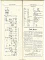
The circuits presented in this series have been designed
by g. a. trench specially for the enthusiast who needs
only a circuit and the essential relevant data
No. 30
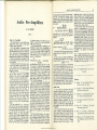
negative voltage (relative to cathode) appearing at the grid of VI very nearly equals the
peak voltage of the AC output from the
bridge.
The grid voltage of Vi varies, therefore,
according to the AC obtained from the bridge.
When this AC is at a minimum (corresponding
to the point of balance) the negative grid
voltage of V1 is at a minimum also, its anode
current being, consequently, at a maximum.
The result of this is that the voltage dropped
across R2 is at a maximum also.
V2 is an RF oscillator which receives its
anode voltage via R2- When the bridge is
balanced, the action of VI causes this anode
voltage to be at a minimum. Owing to the
fact that a simple oscillator (such as the tunedgrid circuit of V2) varies in frequency when
its anode voltage varies, it follows that the
frequency of V2 will vary as the bridge is
balanced, maximum variation occurring at
the point of balance. The oscillations generated by V2 are picked up on any receiver
fitted with a BFO, whereupon the change in
oscillator frequency is converted to a change
of AF tone.
Practical Details
The circuit shown here should offer little
trouble in practice. The valves used may be of
the 6J5 class, and, if desired, can be combined
in a single double-triode. V2 should be capable
of oscillating comfortably over the fairly wide
range of anode voltages passed to it. The choke
in the anode circuit of V2 should be an RF or
an AF component according to the frequency
of the AC used by the bridge. If the frequency
of this AC is very low, C2 may have a value of
1 uF. For higher frequencies 0.1 [iF should be
sufficient.
The value of R2 will need to be determined
R:
V2
Lf
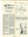
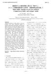
An Accurate Null Indicator
The accurate presentation of null indications
as obtained from bridges and similar measuring
devices can sometimes be a little difficult to
achieve. When a high degree of accuracy is
required it is usual to employ a meter or a
cathode-ray indicator (Magic Eye) to indicate
the point of balance. Very often, however,
an aura! method is employed, in which case
the point of balance is given by an AF tone at
minimum volume level.
This month's circuit illustrates a simple
device which is capable of giving a very
accurate presentation of balance. The indication is still of an aural nature, but the point
of balance is not shown by changes in volume
level. Instead, it is shown by variations of
frequency of an AF tone; the null point
corresponding to maximum frequency change.
It is this point which gives the indicator its
high degree of accuracy, since the ability of
the ear to differentiate between audio frequencies (even when they closely approach
each other) is greater than its ability to judge
volume levels.
To use the indicator described here, it is
essential that the bridge to which the indicator
is connected is operated from AC instead of
DC. The choice of AC has no effect on the
AF tone heard by the operator, and its frequency may lie anywhere between, say. 10
Mc/s and 25 c/s.
A simple resistive bridge is shown in the
diagram; but this is merely for purposes of
illustration and may, of course, be replaced
by any other type of bridge.
Operation
The operation of the circuit is quite simple.
A varying amount of AC from the bridge is
fed to the CR circuit Cl/Rl. The values of
these components, are such that the rectified
C3
II
BRIDGE
OUTPUT
ROSO
AM ACCURATE N U LL INDICATOR
experimentally. It should be sufficiently high
to cause a relatively large variation of oscillator
frequency without dropping the anode voltage
of V2 to too low a value at the point of balance.
A value of 5 to 50 k£2 will probably be needed
here.
The oscillator should work between 10 and
20 Mc/s, the actual frequency being unimportant. The receiver should be so set up that
the point of balance is indicated by a fall in
audio frequency, and not by a rise. Sufficient
input to the receiver will, in most cases, be
obtained by positioning its aerial lead close
to the oscillator.
EYE
SPECIftUST
3
O Q A
" Tell me, how long
have you been suffering from reversed
line scanT'
www.americanradiohistory.com
e> ^
3 a
S Y X
o
pAFF
RADIO CONSTRUCTOR
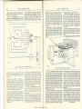
In which J. R. D. discusses Problems and Points of Interest
connected with the Workshop side of our Hobby based on
Letters from Readers and his own experience.
It is interesting to note how popular in switching in the primary of the rejuvenator
the United States are commercially-rnade transformer. This type of rejuvenator is
cathode-ray tube " rejuvenators " for television especially useful for receivers with AC/DC
receivers. These rejuvenators are used with power circuits.
cathode-ray tubes whose emission has fallen
Owing to the fact that the low-voltage transwith age, and it is claimed that they bring a formers used in nearly ail rejuvenators may be
l^rge number of these lubes back to their made very small indeed, these components can
original emission and brightness. They func- be more or less " hung in the wiring " or built
tion by applying a greater healer voltage to the into plug adaptor housings. All rejuvenators
tube than is supplied by the set in which it is appear to have an adaptor plug and socket
fitted and for which the tube was designed. joined together by a short flexible harness, and
Not quite so popular, apparently, are " reacti- are installed by simply unplugging the tube
vators," These are intended also to bring socket and fitting the adaptor socket in its
low-emission tubes back to normal and place. The original set socket is then fitted to
function on the " flashing " principle which the rejuvenator adaptor plug. In one or two
was applied to battery valves many years ago. instances, however, the rejuvenator transformer
A reactivator subjects the tube heater to some- is mounted in a case which has to be screwed
thing like a 50 per cent overload for a minute to the set chassis or cabinet.
or two, this being reduced to a slight overload
Many American technical radio magazines
which is held for a longer period. Reactivation nowadays
carry rejuvenator advertisements;
does not seem to offer as many " cures " to and it is possible
to obtain a very good idea
worn tubes as does rejuvenation.
of their respective physical sizes and trends in
circuit development by studying these advertiseRejuvenators
The retail prices lie between three and
Rejuvenators function by permanently in- ments.
ten dollars.
creasing the heater voltage to the tube; this
Rejuvenators seem to be becoming fairly
being achieved usually by connecting a simple
step-up auto-transformer between the heater standard servicing practice in the United
voltage supplied by the receiver and the heater States, so far as one can judge from isolated
pins of the tube. The voltage increase given articles on this subject. Whether the same will
by the auto-transformer is around 25 per cent. occur in Great Britain is difficult to decide. So
Some rejuvenators use transformers with iso- far as the home-constructor is concerned, of
lated primaries and secondaries, this being course, rejuvenator transformers would be
done mainly to obviate cathode-heater shorts very easy to make or adapt. One point not
which may occur at the increased temperature. stressed in the American literature or advertiseOne rejuvenator uses a transformer with a ments, however, is that, whilst a rejuvenator
mains voltage primary. The heater voltage may bring a new lease of life to a low-emission
originally applied to the tube then heats a tube, it may also ruin it. Nevertheless, if a
resistance element fitted to a bi-meta! strip. tube is in such a bad state that it would be
On switching on the receiver the original thrown away in any case, the use of a rejuvenbeater voltage causes this strip to bend, thereby ator transformer might not be disadvantageous
Another point which is also not stressed is
the question of how long a tube slays rejuvenated at its new heater voltages. This is understandable, of course, because such a period of
time can hardly be predicted. Apparently,
increased lives of a year have been obtained;
whilst, on the other hand, no one is surprised
when the tube becomes " un-rejuvenated"
all over again within a month.
Before concluding on this subject, I should
like to point out, as my own opinion, the fact
that some of the spectacular successes claimed
to have been given by these rejuvenators might,
perhaps, need to be taken with a pinch of salt.
Low mains voltages and inefficient mains
transformers are not unknown, even in the
States. It might happen, in one or two cases,
that a cathode-ray tube has been working for
a long time at a heater voltage, say, 10 per cent
lower than that it was designed for. Increasing
that voltage by 25 per cent (or, even, increasing
it just to the correct value), would be almost
certain to result in higher emission for quite
an appreciable length of time.
Cheap Rectifiers
I was very interested in R. W. Hill's article
in the December issue in which he described
how he managed to use a surplus double-triode
as a full-wave rectifier by strapping together
the anodes and grids of each section. It also
brought back war-time memories to me (and
doubtless to other readers) of some of the
haywire power supply circuits we used during
this period, when rectifiers and transformers
could not be obtained.
1 remember building one receiver (a fourplus-one with 6V6 output), in which a single
home-made 6.3 volt transformer supplied all
the heaters including that of the " rectifier."
HT was obtained direct from the mains by
half-wave rectification, and I found that
American " metal" valves used to cope quite
well with the resultant 200 volts or so which
appeared between heater and cathode. The
" rectifier" used was a 6J5 with grid and
anode strapped! It says a lot for the manufacturer that it never broke down.
An even more spectacular circuit (for which
I was not responsible!) gave half-wave rectification at 300 volts with no limiting resistor. The
builder had fitted a 200 mA fuse in the HT
circuit, but the ripple current used to bum it
out now and again. The heater of the " rectifier " was at chassis potential. In this case, a
metal 6L7 was used.
It seems incredible that valves can be so
execrably treated and still continue to work.
These two circuits, incidentally, are very
definitely not recommended for present-day
use!
www.americanradiohistory.com
505
Tag-Board Leakage
I recently had the task of servicing a receiver
which had an HT leak. This leak showed a
steady resistance of approximately 500 ohms
between the HT positive line and chassis, and
was a little difficult to discover. I eventually
ran it down to a tag-board which had a hidden
leak on the underside of the paxolin between
an HT positive tag and a chassis-mounting
rivet.
Leaks on the surface of an insulator of this
type are common enough, although it is rare
for them to have a constant value of resistance.
They are usually caused originally by a spark
which breaks down the material on the surface
of the insulator, and so causes a fine carbon
track. This assists further sparks until a
definite leak or short is established. The fault
is usually prevalent if the equipment has been
kept for a long time in a steamy or humid
atmosphere which had allowed condensation
on to the surface of the insulator.
An easy way of discovering such a leak
consists of connecting an ohmmeter between
the two associated lines (such as HT positive
and chassis in the case just mentioned), and
lightly pressing suspected tag-boards and
similar components one by one. As the
unwanted carbon track makes contact to the
circuit via solder tags or chassis-mounting
nuts riveted to it, this pressure causes it to be
momentarily connected and discovered, whereupon the ohmmeter needle flickers or shows a
new reading.
The same sort of fault occasionally occurs in
valve holders and switch wafers. In switch
wafers it can sometimes be particularly difficult
to find, since the leakage may occur in the
small rotating disc in the centre of the wafer.
ASTIGMATISM IN ELECTROSTATIC
CATHODE RAY TUBES
(Continued from page 528)
have been undone, and the spot will be
elliptical once more.
The only method would appear to be to
carry out the adjustments on a picture or
test card. This can be a little tricky. It is
not too easy to adjust two potentiometers at
once and observe the effect accurately.
A rather simpler method, shown in Fig. 4,
is particularly applicable if control of spot
shape is required on one pair of plates only.
This is to retain the single potentiometer
control of shift, and to supply the final anode
of the tube also from a separate potentiometer.
507
RADIO CONSTRUCTOR
HTfSOOV
Valves
and
their
Power
SMOOTHING
CHOKF
HT+2SOV —♦—tFPHP* 1
I6O1
-■f>l60
/JF
JJF
5U4
CHOKE
Supplies
13=3
250V
(200m A) O
Part 7
C4
eos-'
FF
Bj F, L. Bayliss a.m.i.b.t.
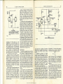
Voltage Doubling Circuits
This short series of articles is not meant to be
a treatise so much as a handy and possibly
useful guide to the radio constructor in his
dealings with power supplies. It cannot, therefore, even pretend to cover the subject fully,
but even as such it cannot be conducted without
a mention of television and voltage doubling
practice.
The two — voltage doubling and television—
are not mentioned together because they have
always been associated thus. Voltage doubling
existed long before television even left the
dreams of its pioneers; only latterly has the
marriage occurred, and a highly convenient
wedlock it has been, and is.
In fact, it is pretty safe to say that nowhere,
except in television, will the constructor have
to use a doublet circuit.
Our first circuit, however, is not concerned
with doubling a high voltage in order to get
an even higher one.
It may be of close interest to the constructor
of a VCR97 tube televisor, though. He,
perhaps taking his HT voltage from a 250V
transformer for vision and sound receivers, is
left stranded for the 400 to 500V necessary to
operate a Miller-transitron timebase circuit.
Usually, only the anodes of four paraphase
valves need to be supplied at 500 volts, and
the current is well under 20 mA.
By taking 250 volts from the cathode of the
full-wave rectifying valve, via C3, Fig. 19, to
the junction of the metal rectifier MR! and
MR2, the ripple voltage across MR2 is again
rectified by MR! and the full mains voltage
(250V) appears across each rectifier, giving
double the voltage between the final HT point
and chassis.
The value of C5 is chosen to pass a current
not exceeding the rating of MR2.
The rating of MR1 and MR2 should be
adequate to cover the external circuit current,
20 mA.
Selenium rectifiers rated at 250V 30 mA are
quite inexpensive, and are suitable.
To find the value of C5, MR2 may be assumed
to have negligible DC resistance and, therefore,
the voltage across C5 to be the full 250V.
The reactance of C5 is
IQfi
2jrfC
where f=mains frequency and C=iJ.F.
As, by Ohm's Law, this reactance also equals
E , we may say that
7
106
250X1,000
2T:fC 30
where 250=the supply voltage, across C5, and
30=the current to be passed by Cs (£0 the
rectifier rating).
tn6v3n
Therefore ^=^^^,^=0.382^.
In practice, MR2 will have resistance,
although its value compared to the reactance
of C5 at 50 c/s (8,3330) will be small.
As the current through MR2 is not steady
DC, the value of C5 may be much greater than
the calculated one and, in practice, 0.5 ttF or
1.0 pF are permissible.
C3 should have a DC working voltage of at
least 750.
An EHT Circuit
If the constructor has a transformer rated at
500--0-500 volts he has no HT problem, except
to drop this voltage to a value suitable for the
sound and vision receivers.
If he were content with a fairly low EHT
voltage — 1,500 volts — his EHT, too, could
be obtained in a manner similar to Fig. 19
previously discussed.
The connections for such an EHT arrangement are shown in Fig. 20. MR1 and MR2 may
each be rated at 600 volts. The capacitors C4,
C5 and Cg should be rated at IkV DC working
voltage, at least; 1.5kV if possible.
With this arrangement, the cathode ray tube
anodes and deflector plates are connected to
the HT + line (via their control resistors and
potentiometers), whilst the tube grid and
0F
C5
6-3 V
8-OA
HT-
CHASSIS LINE
—19
CHOK
3 HENRYS
250m A
it?o
5-OV
3-OA
5U4
ON/OFF
BOOV
HT t
300V
AC
MAINS
2SOV
.WFf 2
H l>
BOOV
ON/OFF
a C2
I6OS Spj-Q-O
AjF
SO
UF
AC
MA NS
SOOV
63V
1-OuF
CHASSIS LINE
C5
MR!
0-5
MR2
330 feQ
-iWAV
EHT
IQGOV
FIG
vum
OR
VUI20
c
EHTf 2KV
Ol
(2&T
OI C2
/iFKV
2-0
iHTRCI91
www.americanradiohistory.com
chassis line
4:
AUDIO TRANSFORMER^
ON/OFF
BOOV
AC
-.1
MAINS
hooov
2-OV
OR
4-0 V
2 SO
bG
V2
251
bO
vU 120
VUI1I
20 v
OR
40V
HEATER
TRANSFORMER
£1^21FOR POSITIVE
AN ARRANGEMENT
EHT
511
RADIO CONSTRUCTOR
Magnetic
Recording
Equalisation
BOO
itn.
—with some amplifier modifications
||C.
"P
RC194
FIG.I
'SRIDGEO-f NETWORK
SWITCH CLOSED ON 'RECORD'
OjnF
BOpF SOpF
«h—Ml—Hi
i- " >
>TFiEBL
i SlOO <500
SbO %500
1
f
f
\ kn '
6J7
IT*
ista
magnetic reproduction of a constant amplitude
recording Similarly the bass fall-off in disc
recording). Consequently, it is not advisable
to emphasize the bass frequencies during
recording as the tape would easily saturate.
If the microphone response lacks bass, however, enough compensation can be added to
correct it.
The drop at the high frequency end is due
to the transfer characteristic between head and
tape, and includes iron losses and gap effect
losses. These are common both in recording
and reproduction, so that an equal amount
of top boost may- be applied in each of these
positions. If, in fact, all the boost were
applied only on playback, the recording signal
level at these frequencies would be correspondingly down relative to tape noise level, and
signal-to-noise ratio would not be so good.
The usual type of simple compensation
filter consists of a bridged-T network as in
Fig. 1, and such an arrangement was used
in the magnetic recorder described in the
Sept., Oct. and Dec., 1952 issues.
The condenser C2 is shorted out on "record,"
giving top boost only. When C2 is in circuit
on " play " both bass and treble boost results.
While such a circuit can give correct bass
compensation, the rate of rise at treble frequencies is not sharp enough to give perfect
correction at the top end. It is important that
negligible boost occurs in the region of 15002000 cycles relative to other frequencies,
either on " record " or " play."
A method employed by some commercial
recorders is to use an inductance tuned to
about 7 kc/s. This method has many disadvantages, however—(a) expense, (b) it is
prone to hum pick-up by magnetic induction,
(c) the circuit " rings " on transients and the
response to square wave testing is in genera!
undesirable, unless some form of artificial
hangover is required to compensate defects
elsewhere in the system.
lOpF
ioo
m
II
By L. F. SINFIELD a.m.i.p.r.e.
One of the chief difficulties in magnetic
recording is to obtain correct frequency compensation in the amplifier.
If a recording is made on good grade tape,
such as "Scotch Boy" tape at
second,
with a head gap of between 0.5 and 0,75
" thou," then if the recording is made at
constant current the playback amplifier will
require approx. 18-20 db boost at 100 cycles,
no boost around 2 kc/s and approx. 15-18
db boost at about 8 kc/s.
To obtain maximum signal-to-noise ratio
it is obvious that the maximum recording
level should be used, but the peaks should
not extend into the saturation point of the
tape. This is almost unavoidable, however,
in general practical applications, but the
number of such peaks can be kept down by
good recording technique, and the best use
of microphones and the best recording level
can soon be determined with experience.
The fall-off in bass reproduction at a rate
of 6 db per octave is a basic characteristic of
IB
. oo
250
3-3
Vf;
ta
itn
BOJJF
Mn
BASS
FfCI95
SWITCH CLOSED
FIG.2
ON 'RECORD'
PRE-AMPLIFIER AND COMPENSATION NETWORK
After extensive tests with an oscillator and
oscilloscope on a large variety of networks
the circuit of Fig. 2 has been found to be
most satisfactory. The bass boost action is
similar to that of the bridged-T of Fig. 1,
The treble boost, however, now consists of
a two stage high pass filter C1/R1-C2/R2.
The bridging condenser C3 corrects a small
chip in the curve caused by phase shift. R.2
is made a variable to have some form of boost
control. This is effective on both " record "
and " playback " to allow for acoustic and
other conditions. The 1 Megfl bass boost
control is only effective on " playback," and
this combination will be found to be most
adaptable in practice.
The actual bass boost is rather more than
the " calculated " network boost, as there is
a reduction in shunting of the anode load at
tow frequencies, so giving greater stage gain
in the valve.
Figures of gain, etc., at maximum boost
are given at Fig. 3. These were taken with
about a foot of screened lead to the 1 MegO
output load (next stage grid resistor) to
simulate actual installation conditions. This
1 MegD grid resistor should be in fact, a
1 Megfl volume control to the second stage.
The second stage should also be a pentode
www.americanradiohistory.com
VOLUME
MO
in order to reduce input capacity caused
by " Miller effect" which would attenuate
high frequencies, especially at midway settings
of the volume control.
The overall gain of the pre-amplifier and
network at 1500 cycles (the point of maximum
network attenuation) is 10.5 db, valve gain
being 35 db and network loss 24.5 db. The
output waveform is sinusoidal for similar
input if input level to the 6J7 is kept below
0.3 volts. However, the output of microphones
or tape heads is well within this limit.
If a condenser of 0.00025JJIF is fitted in
parallel with the lOOkfl in the network, then
the treble boost can be limited to 9 kc/s.
Beyond this frequency the effective shunt
on the anode load reduces the output. This
condenser also improves the phase shift of
the network, but gives a slight amount of
treble boost at minimum position of treble
control:—1-3 db at 10 kc/s; this amount is
negligible, however, when compared with
tape losses. Its fitting is optional .
The compensation given by this preamplifier and .network almost perfectly compensates for tape losses in a good system.
The amplifier following should be flat, preferably with negative-feedback. The output
resistor for constant current recording should
512
RADIO CONSTRUCTOR
RADIO CONSTRUCTOR
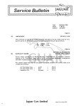
Fig. 3. Relative gain of pre-amplifler and network
Maximum treble arid maximum bass
Playback
Overall
quency
Record
db
db
'db
50 c/s
100 c/s
200 c/s
500 c/s
I kc/s
2 kc/s
4 kc/s
6 kc/s
, 8 kc/s
10 kc/s
-3.0
-1.25
0
0
0
+ 1.0
+ 5.3
+7.5
+ 8.7
+9.3
Valve gain at 1500 c/s
Network loss at 1500 c/s
Overall gain at 1500 c/s .
+23.75
+20.75
+ 17.5
+ 11.0
+ 4.75
0
+ 5.8
+ 8.6
+ 10.0
+ 10.5
. .
be several times the impedance of the head at
the highest recorded frequency. The bias
should be about 50 kc/s and of sinusoidal
waveform, with a rejector circuit to isolate it
from the audio output. The correct bias
level for good response will be found by
experiment. On " playback " the frequency
response of the head and any head matching
transformer should be fiat, with the possible
OUTER MU-METAL
SHIELD SPACED FROM
HEAD^.
BAKELITE
BLOCK \
SUPPORT
HOLE IN BOTTOM
cover oPagED
OUT TO KDIAM
NOTE EOLT
MUST ftE
OONPLETELY
ISOLATED FGAlNST
DIRECT EONDING
TO CERTRE OF
HEAD UNDER
COVER
HEAD
DECK TOP
PLATE
z
FIXING NUT
FIXING BOLT
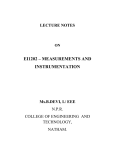
FIG.4
MODIFirATION TO HEAD TO PREVENT SHORTED
TURN"EFFECT
Al remove outer nut
b)
■ BOTTOM PLATE
C)
INNER NUT
D) OPEN HOLE IN BOTTOM PLATE TO DIA
E) REPLACE BOTTDM PLATE BUT DO NOT USE
INNER NUT
FO MOUNT HEAD CN INSULATED BLOCK AS
SHOWN TO PREVENT BONDING TO BOLT
RCI96
-
+ 20.75
+ 19.5
+ 17.5
+ 11.0
+ 4.75
+ 1.0
+ 11.1
+ 16.1
+ 18.7
+ 19.8
513
1
Minimum bass and
minimum treble, db
^1 i,i .v v/i,.iv iv11 i ir ir.K
i* 1 t
taken with calibrated
attenuator and oscilloscope. The bass boost
at tow
•a?ue 33 the shu!ltmg on the 6J7 anode load is reduced
tni stray capacities
v normally
playback,
so giving ifgreater
The figures
alsowere
allow
for )valve
and
encountered,
built stage
to thegain.
instructions
which
given
fi r
u y3X6 r a<;tuaI
u Su es
r
fm mi nHpC o " ^
-3.0
-1.25
0
0
0
0
0
0
0
0
. +35 db
. -24.5 db
. +10.5 db
exception of a shunt resistor and condenser
to give cut-off beyond 9 kc/s.
The pre-amplifier and network may also
be used with a high fidelity pick-up for gramophone reproduction if the pick-up output is
less than 0.3 volt. Bass and treble boost
controls can be adjusted as required. Any
treble cut required for scratch filter, etc.,
should be in the form of resistor and capacity
shunt directly in parallel with the pick-up
and should, therefore, be mounted on the
player unit.
There is a slight drop in valve gain (independent of the network) at 50 cycles of about
3.0 db due to the value of the screen decoupling
condenser. If it is desired to reduce this drop,
then this condenser should be increased to
0.25jj.F or 0.5{rF.
Modification to Magnetic Recorder in Sept.,
Oct. and Dec,, J952 issues
The recorder previously described can be
improved by incorporation of this network
in place of the original bridged-T.
After experimenting with the Qualtape head,
certain improvements have been found possible.
In its normal condition the fixing bolt shorts
together the centres of the head cover-plates. ■
Therefore, a continuous shorted turn is
formed by the case and the fixing bolt arounc
each pole piece. By insulating the bolt frorr.
the lower cover-plate, the shorted turn is
eliminated and the inductance, impedance
and output are increased and damping considerably reduced. Fig. 4 gives full detafis
of the alteration.
In view of the increased impedance, the
load resistance on the secondary of the input
transformer should be increased to about 500kn,
Another alteration is in the deck layout.
One of the guides is removed and the erase
magnet mounted on a swinging arm.
:::
O luF
60 pF
z
to
JMEG a
*cm
e r n tiV
ven 01
and
" r™
L^lueSandTnoglbass
I C-W
C2 =0.005!rF. C is shorted out as for
r H " position
recoid
boost
occurs on this position
Treble response is given for a trimmer set to a fixed 60 pF capacity. If the recorder circuit
boosT—AU figures^db^ift'
resp0nse 0f the nelwork wil1
of course be flat with no treble
C=0.0)uF
Frequency
100 c/s
200 c/s
Record (C Out)
0
0
0
Play (C (n)
17.5
14
6.6
1.3
Total
16,2
12.7
5.3
0
500 c/s
1000 c/s
2 kc/s
4 kc/s
8 kc/s
1.8
4.5
7.6
0
3.0
6.3
0.5
6.2
12.6
2 kc/s
4 kc/s
8 kc/s
0
1.8
4,5
7.6
5.5
0
0
C=0.005nF
jfrequency
Record (C Out)
100 c/s
200 c/s
500 c/s
0
0
0
Play (C In)
19.7
17
11.5
Total
17.9
15.2
9.7
1000 c/s
2.7
5,7
3.7
0
5.4
11.8
Use 0.01 vF for 72 ins/sec—normal heads—medium coercivity tape
Use 0,005|j.F for 15 ins/sec—normal heads—medium coercivity tape
These figures do not include other slight compensations incorporated in the amplifier.
www.americanradiohistory.com
RADIO CONSTRUCTOR
514
STOP SCREW
ORIGINAL GUIDE
REMOVED
64
TD FEED \\
SPOOL
/ ///,
HEAD
Bass - Lift
For
AC
Four"
Mains
l
By A. CARPENTER
(LEADiNG EDGE
" MA3NET ROUNDED OFF ,
TRAILING EDGE 4
FROM TAPE IN .
SPRING WASHER
ERASE POSITION)
30LT
//
SWINGING PLATE
FIG.5
ERASE MODIFICATION TO REDUCE
THREADING a TO STABILIZE TAPE FLATNESS
RC19V
There arc'severai reasons for this.
(a) Less threading is involved
(b) As threading is similar on both " record " and " play " the frictional losses
and load are equal, and so ensure
correct speed.
(c) The greater " wrap " around the pillar
adjacent to the head eliminates tape
tilt which was found to occur when
feed spool braking was light enough
to eliminate capstan loading.
The arrangement is shown in Fig. 5.
The magnet will produce least background
Book
noise if the trailing edge is spaced about
1/16th inch away from the tape by tiltsng the
magnet. The leading edge has been rounded
and polished to prevent it scraping the coating
off the tape.
A further modification incorporated was
to increase the series constant current resistor
in the amplifier from SOD to lOOfl, due again
to increased head impedance.
The bias isolation choke can be made to
give better rejection by tuning it and making
it into a proper tuned rejector circuit. A value
of about 0,02[j.F should be satisfactory for the
tuning condenser.
Review
the derivations of many of the formulae in the
TELEVISION RECEIVER DESIGN—l.F. STAGESe gives
several Appendices.
.
By A. G. W. Uitjens. 172 pages 114 illustraiions.
Gain and bandwidth with two-termmal and fourPrice 21s. Distributed in England by Cleaver-Hume terminal networks occupy only a few pages, but their
Press Ltd., 42a South Audley Street, London, W.l
applications in multi-stage amplifiers employing staggered
and the response curves obtainable, are giyett
The Philips Technical Library has this latest addition. tuning,
Distortion in double- and vestigialBook V11I.A, as a companion volume to those already fuller" treatment.
systems is discussed in another chapter.
established as standard references on radio theory. sideband
The
effects,
and
the
use of, feedback in l.F. amplifiers
Dealing entirely with the l.F. stages in television receivet is given over to a large part
of the book. It is enlightening
design, this present book adequately covers all the to read that the chassis can
become a wave-guide tor
factors which need careful attention m order to produce feedback energy, and that a remedy
maximum gain with required bandwidth. The attainment the use of a long, narrow chassis. . is to. be. .found. in
of satisfactory noise level, and the calculation of noise
considerations of0 circuit design have
factor, is of particular interest where the design ot notThebeenpractical
forgotten; a chapter on this aspect deals with
•' fringe area " receivers is concerned.
some typical examples of sensitivity, gam, selection ot
In an exposition such as this where one specialized valves, staggered tuning and distortion.
,, ,
branch of design technique prevails, it is inevitable that
There is no doubt that this reasonabiy-pnced book
the mathematics of the subject should be given some can be of considerable value to the design engineer.
prominence. The author has kept the mathematics as
NORMAN CASTLE
simple as possible in the main body of the book, and
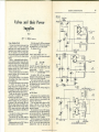
The receiver to be described was built
originally as a simple 3-vaIve arrangement
using an RF stage, diode detector and LF
amplifier feeding into an output pentode.
This proved fairly satisfactory, but the output was not quite sufficient, and, as the author
likes plenty of bass, experiments to obtain it
still further decreased the output—as is usually
the case. After various changes the following
circuit was evolved.
Circuit
As will be seen from Fig. 1, four valves are
used. VI is a high gain RF pentode supplying
a good signal to the detector, and fed via a
small trimming condenser (C5) to the second
tuned circuit. This method provides a certain
amount of variable selectivity, and when the
best position is found should require no further
adjustment.
Demodulation is obtained at the diode of
V2, which is a duo-diode triode. The second
diode, normally used for AVC purposes, is
not used and can be connected to cathode.
The triode portion of V2 is usually used
purely as an LF amplifier, but in this circuit
it is arranged principally as a bass amplifier.
The resistors R6, R7 and the condenser CIO
cause the valve to discriminate in favour of the
lower frequencies, and afford a considerable
degree of bass lift. This is not achieved without
a severe loss in gain, and the output from V2
is, therefore, only small.
HF is filtered out by R4 and C9. R 5 is the
diode load, C8 is the coupling condenser and
R9 serves as grid leak. The grid is fed from
the junction of R6 and R7.
Output from the anode of V2 is fed via
Cll to the volume control potentiometer, R15,
and thence to the grid of V3 which is another
RF pentode. This valve acts well as an LF
amplifier when connected as shown.
Coupling to the output valve is by means
of a para-fed LF transformer with a ratio of
1:4. This was used in place of RC-coupling so
that the negative feedback circuit, C17, R17,
Ri8 could be used to cancel out distortion,
www.americanradiohistory.com
which may be as much as 10% in the output
valve.
The introduction of feedback causes a
decrease in gain, as may be expected, but this
has been taken care of in the earlier stages.
Operation of the potentiometer R18 varies
the amount of feedback, and with the values
specified gives a wide range of tone control.
With feedback at a minimum, speech is crisp
and clear. As the control is rotated bass
becomes more and more evident.
The writer uses a 10-inch speaker mounted
on a sheet of asbestos 3// (sin x 2ft. Reproduction is good and in the order of 5-6 watts.
Bass is plentiful.
Lower Supply
In the original receiver a selenium metal
rectifier is used in conjunction with a halfwave mains transformer. This transformer is
of ex-Govt. origin and has a secondary of 300V
at 100mA_, plus a 6.3V winding. Mains hum
is not noticeable and so it was decided not to
go to the expense of installing full-wave
rectification as is usual.
Theoretically, and probably practically,
full-wave rectification would be an improvement and this is a point to bear in mind when
building this receiver. One point in favour of
the metal rectifier is that it is cheap. It is also
cool and requires no heater supply.
Conclusion
No definite layout is shown as constructors
will doubtless have varying ideas regarding
this. The original was built on a metal chassis
12in x Sin X 2in, fitted with a black cracklefinished louvred lid Tin in height, both of
ex-WD origin. No internal speaker is fitted
and the underneath of the chassis is left open.
In case of breakdown or alteration, all that is
necessary is to turn the receiver upside down
and the majority of the components are
accessible immediately.
The four controls, tuning, wave-change, tone,
volume-on/off are arranged along the front
panel, in that order, from right to left.
516
RADIO CONSTRUCTOR
RADIO CONSTRUCTOR
o:
cj
r--
—'TSTST'
wm—ww—
og ,
ck'
noiil
u
}3
A/WW—
I
JMiuuui
'rmwA
MUM
WAV
WvW—
ww
-ww—
cou Q:
\o
r- ^
FWVWWArii—II
H
Ht
—WW—
COMPONENTS LIST
C16
5(V.F-12V
250 kO
C17
0.002(iF
10 kD
CIS
8jxF-500V
150 n
019,020
0.1 |xF-2000V
50 k£i
Mains transformer-300V, 100mA; 6.3V, I,5A
500 kQ
(or see text)
100 kQ
Selenium metal rectifier; 250V, 100mA
1000 Q
Chassis-12in X Sin x 2in
1 MQ
LF Choke-20H, 100mA
20 kQ
LF Intervalve transformer 1:4 (Premier Radio
1 MQ Pot. and switch
or similar)
490 Q
Aerial and RF coils, long and medium wave
50 kQ Pot.
(Premier Radio)
2-pole 2-way Yaxley type switch
0.01 [iF-350V
High Frequency Choke
500pF ganged with trimmers Tapped output transformer
0.IuF-450V
Four 10 valve holders
IOOdF trimmer
Fuse (2.5V bulb)
Iu.F
Valves
IQOpF
25^F-12V
VI, V3 — 6SH7
16[rF-450V
V2
— EBC33
32,aF-500V
V4
— EL32
Trade
WAV
WW—
-WAV
Resistors
R1
R2, R7, R17
R3
R4, RJO, RI2
R5
R6, RU
R8, RI4
R9
RI3
R15
RI6
RI8
Condensers
C!,C2. CIO
C3
C4, C8, Gil, C14
C5
C6
C7, C9
CI2
CI3
CI5
sjuioos
• I
w
We have received from Kendall and Mnusley,
99 Dudley Port, TiptOn, Staffs., samples of
their products for review. One Liof these, a
pair of meter stands, was at once snaffled "
by Centre-Tap, and is described by him in
Radio Miscellany in this issue.
The other items submitted consisted of a
cabinet, front panel, chassis, and a pair of
handles. These were stoutly constructed and
nicely finished in black crinkle.
The prices charged are reasonable; for
example, a cabinet 10f X 12 x lOi" deep with
light alloy panel costs 21s. A chassis to suit,
measuring 10' square by 2)' deep, is available
at lOsv 6r/.
Items are obtainable in other colours than
black. Brown, blue and green can be supplied,
at 10% extra.
Another useful item, and one which we
have not seen elsewhere, are metal plates
punched to take an international octal or
Review
similar valveholder, and designed to allow
easy fitting in place of existing larger holders
of obsolete types. These are also reasonably
priced, at 3j 6t/ per dozen.
The firm also supplies valves, components,
and sundry other items, and readers interested
are invited to send a lid stamp for their lists.
Clydesdale Supply Co. Ltd., 2-Bridge Street,
Glasgow-C.5., have sent us copies of the new
List -No. 8D and Supplement. These are
charged at Is (td, which is refunded on the
first purchase.
We cannot think of a more comprehensive
Jist than (his,-with its 260 pages which, with
the numerous illustrations, forms a most
handy reference book apart altogether from
its primary purpose.
wwWm atnllnhle
—VvWA
DATA BOOK. To. 7
2/0
RECEIVERS, PRE-SELECTORS AND CONVERTERS
^«fc
■cnrm
DATA PUBLICATIONS 57 Maida Vale London
www.americanradiohistory.com
517
Telephone CUN 6518
519
RADIO CONSTRUCTOR
Radio
Control
Equipment
PART 4
By RAYMOND F. STOCK
Manual Unit
A simpler but very effective device which
also carries out the same function is the
pulsing switch shown in Fig. 18, which I
recently developed for another purpose (mentioned later),
A is an insulating arm conveniently cut
from a I' thick perspex, and it is mounted on
the end of a short control shaft. The latter,
complete with its bush, can be taken from a
discarded potentiometer.
Pivoted on a 6-BA bolt at the end of the
arm is a small swinging link B, which is normally kept at 90° to the arm by the light
spring C soldered between the link and an
8-BA screw in the arm A.
'■ j
o
A
o
C (8
O
C_3
Fig. 18. Manual pulsing unit; scale in inches. In the sequence diagram A,
S ami P represent Amidships, Starboard and Port.
C19
Fig. 19. Manual pulsing unit, complete on perspex base.
As the arm is rotated through its three
positions, the link tends to move through an
arc of a circle, but it carries a small peg at
the end which interferes with the two guides
D and E. These cause it always to move under
them when travelling away from the centre,
but trap it above them when travelling inwards.
The peg therefore follows a kind of figure
eight path as the arm A is rocked from side
to side.
Several contact strips F are soldered to
pillars screwed into the insulating baseboard,
and as the peg moves through its path it
brushes against these strips and in so doing
keys the transmitter. The keying leads are
taken, one to all the contact pillars, and one
(via a copper pigtail) to the end of the spring C.
If the movement of the peg is studied against
the small sequence diagram printed alongside, it will be seen that the correct number
of pulses are sent to step the escapement
round correctly.
In making this device, the peg at the end
of link B should be allowed to pass well clear
of the ends of guides D and E, or there may
be a tendency for the peg to return along the
incorrect path. The position of the peg at
the ends of its travel is, of course, determined
by the travel permitted to lever A.
The guides are made up from scraps of
18 swg brass sheet bent to shape, and sufficiently accurate dimensions may be taken from the
scale in Fig. 18. The sketch Fig. 19 shows a
view of the completed parts.
When either of these two pulsing units are
used, a simple press button should be included
in the control box, wired in parallel with the
www.americanradiohistory.com
pulsing contacts. This is useful for getting
the mechanism in the model into phase, and
enables the operator to correct any error
which may creep in when under way, A means
of sending signals by hand should always be
available, as the chance of a spurious or
undetected impulse is always present, and
once the system gets out of phase it can be
most confusing !
Selector Mechanisms
A more complex and, therefore, generally
more flexible way of using a sequence system
is by utilising a circuit selector.
mniiiM I immi
A
O
C20
Q Hjg
C
Fig. 20. Selector-, operating mechanism
RADIO CONSTRUCTOR
520
Most readers will know how these components work, but Fig. 20 is a guide to the
construction of a typical unit.
A is the electromagnet which in radio
control work is energised from the receiver
relay contacts. B is its armature and C is a
S
RADIO CONSTRUCTOR
In one scheme the selector can be regarded
as the equivalent of an escapement, with a set
sequence of positions provided by the various
steps. Each step can then be wired to an
electrically driven follow-up device and represents a definite rudder position. Initially
I
polarized positive and negative by pigtail connections to a battery. Since the motor is
connected between the battery centre-tap and
the selector (common) it is supplied with power
via one of the brushes—the one selected—and
either of the two segments, whichever one the
brush happens to be resting upon will decide
the polarity of the vottage applied to the
motor, and thus determine its direction of
rotation.
This direction is such that the insulating
space between the copper segments always
moves towards the supplying brush. In effect,
then, the gap between the segments homes on
the selected brush, and the unit forms a simple
follow-up device, sensitive to nine different
positions.
521
radio connection Strip bent into an arc.
Flexible insulated pigtails carry power to
the two moving segments. The final power
take-off to the steering gear can be by a pushpull rod pinned to the end of the operating
lever shown, which moves with the disc. The
lever on the rudder shaft can be the same
length as the operating lever so that the two
move in step, and in this case one obtains
full control from port 20° to starboard 20°
in 5° steps.
Any small commercial motor will do for a
power unit, a number of inexpensive permanent
magnet motors being available. As an index
of performance the following notes may be of
interest.
An electrically driven actuator was recently
\
/
. jD-/
.
O
C2(
22
Fig. 21. 9- Way selector in simple steering unit.
pawl which works on a ratchet wheel. Very
often a detent is provided against the wheelto prevent reverse rotation, as shown in the
drawing.
Each time the magnet is energised, on
receipt of a signal, the pawl rides over a
tooth of the wheel; when the signal terminates,
the armature returns by spring tension and
carries the wheel round one tootfu A wiper
arm (or arms) is mounted on the shaft of the
wheel, and rotates over a ring (or rings) of
contacts, thus switching various circuits.
Obviously, the limitations of this device are
decided by the number of wiper arms and the
number of positions, and an enormous number
of combinations are available. In most cases
the constructor will arrange these to his own
requirements, but some illustrations of the
commoner circuits in which selectors are used
will be given.
Fig. 22. 9-Position follow-up mechanism.
this may seem no advantage over the escapement, but there are two important differences
—the foilow-up mechanism need not operate
until the selector finally " homes" on a
selected position, thus avoiding moving the
rudder through unwanted positions. Secondly,
the selector can work at very high speeds, so
that a larger number of steps can be used in
the sequence (providing finer control) without
slowing down the response.
An example of this straightforward use of a
Selector is given in Fig. 21, which shows the
circuit of a nine-step selector wired to give
four port, four starboard, and one amidships position.
Each of the selector contacts is wired to its
own brush, and these nine brushes bear upon
the surface of an insulating disc driven at
slow speed by a permanent magnet motor.
Mounted on the disc are two copper segments
with a small gap between them, and they are
Fig. 22 is a drawing of an easily made unit
on these lines. The small motor is coupled
by a short length of spring to a reduction gear
train which is most compactly made from two
worm and wheel stages, as shown, but if these
are not available the gear train from a small
clock will do very well; often the motor can
be coupled to the seconds hand shaft, which
projects beyond the frame sufficiently to take
a soldered coupling, and the final drive can be
mounted on the hour shaft, thus giving a
reduction ratio of 3600:1. ifhe rest of the
mechanism is cut away.
The contact disc shown is a circle of paxolin
bolted to a brass hub; contact segments are
cut with scissors from hard brass or copper
foil having mounting lugs turned over through
corresponding slots in the paxolin. Copper
foil brushes are arranged firmly to bear on the
disc at 5° intervals, their fixed ends being
supported by a perspex arc; alternatively,
they can be soldered to the tags of a suitable
www.americanradiohistory.com
made up using an Electrotor driving a gear
train of 1000:1 ratio. On 4.5V applied to the
motor, the current consumption (light) was
0.25A. A load of lib was then applied to the
output lever, which had an effective radius
of 1.7", and the current rose to 0.35A, the
lever taking 4 seconds to move through 60°.
A force of 1 lb is, of course, far more than is
needed to shift the rudder of a model boat,
and in this case was designed to operate the
steering gear of an armoured car model (total
weight 8J/f>).
Selector systems similar to the one described
can be designed with any number of positions,
the limiting factor being the time delay that
can be accepted for operation through a
complete sequence. Any selector should be
capable of interpreting at least 10 pulses per
second; in model work it is advisable to check
the positive operating speed when the batteries
have fallen to their accepted miminum voltage.
{To be continued)
RADIO CONSTRUCTOR
TV and its alleged rival, the third dimensional
film, have been much in the news of late, and
this, added to my recent comments on colour
and stereoscopic TV, seems to have provoked
a number of letters from readers. So much
so that I feel I am left with no other alternative
than to treat these as the topics for the month.
As so few details of the colour and stereoscopic
processes have been made public it is only
possible to consider them in a general sort
of way, and we are still very much at the
guessing stage about the probable date of their
full introduction.
There is, however, one outstanding development which may have an important bearing
on the proof of their practicability. I refer,
of course, to sponsored TV. The Assistant
Postmaster General recently revealed that
46 enquiries for sponsored TV licences had
been received. There were also 26 enquiries
about buying time in the sponsored programmes. The possibility of alternative TV
programmes being available before the end
of next year will, for many, make cheerful
reading. Unfortunately the more alternative
programmes we have, the narrower the chances
of getting colour or stereoscopic transmissions
become. All present systems require three
times the bandwidth of monochrome TV, and
the only way of squeezing them all in is to
move them to still higher frequencies- Apart
from disturbing the present allocations in
the VHP spectrum, the further HF we go the
more restricted becomes the range of each
transmitter.
Competition
Nevertheless, it is becoming increasingly
important for these problems to be seriously
tackled. "We must regain our diminishing lead
in technical developments, A couple of years
ago, we, and America, had a very iong lead
over the rest of the world. But TV has
expanded rapidly since then. According to
Unesco, 55 countries are now engaging in
some form of regular TV activity. Japan,
Cuba and most of latin America are all well
in the running. Even the small republic of
Dominica has had regular transmissions for
over eight months!
Admittedly we have supplied much of the
transmitting equipment, but the sales of our
receivers has not been in proportion. With the
entry of Japan into the receiver market at
cheaper prices, the need for retaining our
technical superiority becomes paramount.
The same, too, applies to a lesser degree to
Germany. Before we can sell" colour or
stereoscopic TV to the rest of the world we
must provide a system which necessitates only
a cheaply-produced, reliable receiver and a
daily service to prove its practicability.
Just how important the 3-D aspect will
become is a matter of speculation. Colour
seems to be not only the more important,
but also the more logical step.
To meet a few requests, and for the sake of
beginners, a brief review of the colour systems
is included in augmentation of my comments
of a couple of months ago. Two of them are
based on the fact that by adding together in
suitable proportions red, green and blue light,
any desired colour can be produced. This may
be achieved in two ways. Firstly by projecting
them simultaneously, and secondly by scanning
them consecutively. Just as it is impossible
for the eye to detect a single "scan," repetition
at a high rate presents an apparent single,
complete colour picture to the human eye.
The principle of adding two or more colours
to produce another—generally referred to as
the " addhive" system—has already been
widely used in other fields. Painting, printing
and filmcraft readily spring to mind. The
disadvantage of additive systems for photographic and TV purposes is that it entails the
use of filters. The high absorption of light
in the colour filters reduces the recorded
image to a dimness that demands an extremely
high order of sensitivity or an intense subject
lighting, or more usually a combination of
both.
The subtractive system, widely used in
cinematography, produces colour by subtracting from white—which is a combination
of ail colours.
A limited colour system can be obtained
by employing only two colours, red and bluegreen. In fact, a two-colour system was
actually used in a pre-War Baird demonstration which employed a twin cathode ray
523
Unfortunately the development of colour
tube projecting two beams on the same
fluorescent screen. The superpositioning gave TV in Great Britain, at least, is not solely
a fairly wide and reasonably accurate colour based on the near-perfection of any system.
It depends on the provision of programmes.
range.
The RCA system has been developed on No programmes—no receivers. No receivers
similar lines. Three separate images, after —no programmes. Thus we find ourselves in
sorting out from the signal, are superimposed a vicious circle, but having completed that
on the same screen. Such a system, although circle we ourselves have gone round in another.
it means complication in the CRT, is theore- We get back where we came in—sponsored
tically practical and development will lead to TV ! This might yet prove our ray of hope.
If sponsored TV doesn't develop colour it
its simplification. It would, however, make
may very well help by relieving the BBC of
all our present equipment obsolete.
Not only are three separate beams each some of its programme commitments so that
from their own " gun" required inside the they can open up new fields in experimental
tube, but a great many circuits in the receiver colour transmissions.
will have to be in triplicate. No wonder Alternatives
designers have given much thought to proColour and stereoscopic TV must come, and
viding a means of producing colour with
minor modifications and additions to our we all want to see Great Britain in the vanguard. With the present set-up we are hamexisting receivers.
strung to our 405 line, 50 traversal-interlaced
Mechanisation
f.p.s. system which we started in 1936 ! Would
The most direct way of adding colour to we decide on it again if we were free to choose
our existing system is mechanical. Again, of to-day, and what alternatives are open to us ?
course, we are dependent on the mixing or Firstly we can supersede it completely while
subtraction of primary colours. Columbia we temporarily carry on the present system
developed a system using a revolving filter side-by-side with a modernised system, until
disc in front of the camera. A similar disc the existing sets " wear out." This sounds
has to be rotated in synchronisation in front very nice, but it's wasteful nationally and we
of the CRT of the receiver. It was used for still shan't know if the new system is going
lllllliliilllllililiiUllillllllllliliM^
iiinigiiiiiiiMiiiiiiiiiiiiiiiiiiiiiiniiiiiiiiiiiiiiiiiiiii!
talks STEREOSCOPIC AND COLOUR TV |
B
,
"T
tallzs
| Centre Tap about
A GADGET
a time in America and a number of receivers
sold, but it had to be discontinued by government intervention on the grounds that it
would upset the Defence Programme.
Pye Radio, EMI, the Marconi Co. and the
BBC are all carrying out experiments along
these lines, and although satisfactory colour
demonstrations have been given, just what
sort, of results could be achieved on ordinary
domestic receivers in the home is rather
problematical. Those of us who are still
beset with nightmares of our disc-scanning
days will find some difficulty to work up much
enthusiasm for mechancial colour discs. Nor
does anyone dare to commit themselves on
the question of costs—not only the cost to
the viewer but also at the transmitting end.
We still need three times the bandwidth, and
a move to the HF means lessened ranges and
more relay stations.
RCA are making strenuous efforts to develop
an improved all-electronic system, and those
of us who think mechanical colour discs too
high a price even for reasonably accurate
colour, watch with eager eyes.
www.americanradiohistory.com
to prove the ultimate one.
Secondly, we can have a patchwork arrangement whereby we attempt to make existing
receivers adaptable by minor modification
(or additional stages) to gain partial improvements. Unfortunately the BBC seem to be
moving along these lines. This sort of compromise has little to recommend it and there
is always a danger that we shall land ourselves
in such a tangle of makeshifts that further
progress becomes impossible without, at
some remote date, having to make a completely
fresh start. Timidness on the part of the
BBC may be storing up a much bigger hardship
for viewers in future years.
The third possibility is wired TV. In any
case VHF gives only a local range. Wired
circuits could give nation-wide coverage with
alternative programmes. The question of
bandwidth no longer has to be solved. It
would, however, be an enormous undertaking
and might take years to get into operation
even if there are no unexpected snags. By
[Continued on page 533
525
RADIO CONSTRUCTOR
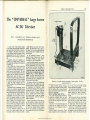
The
" UNIVERSAL " Large Screen
FOCUS MAGNET
\
AC/DC
Part I.
Televisor
Described by A. S. Torrance, a.m.i.p.r.e., a.m.t.s.
(By kind permission of ikopatents ltd)
FOCUS
CONTROL
\
A recent survey of the electricity supplies
in this country has surprisingly revealed that
many people are still tied down to the limitations imposed by DC (direct current) mains.
It was, therefore, decided to present a design
encompassing both AC and DC mains, and
which also covered all voltages from 200 to
250.
Fortunately, valves and equipment are
available for this design, which is based on
series heater-chain technique, and is approved
by Mullard, Ltd.
Such a design also, of course, means that
the intending constructor must bear in mind
at all times the dangers attendant upon the
chassis hcing at mains potential. This need
for caution is particularly important whenever
operating tests are carried out during the
building period, when the chassis is not
protected by the cabinet and a careless moment
may have serious results. We do not intend
to be macabre, but you will not be allowed
to forget this highly important aspect of
AC/DC technique, for we shall make constant
reference to it.
The system also has its advantages, and the
compact and remarkably lightweight design
possible with this method is readily appreciated
from the illustrations which will be appearing.
A good idea may be obtained from the
accompanying view of the chassis structure,
which when properly installed in a cabinet
will be perfectly safe for all members of the
family to handle. On the structure shown
will be the complete receiver; CRT, speaker,
sound and vision strip, timebases and all the
requirements to suit electrically the various
mains supplies wherever it may appear.
All five transmitting channels will be
covered by a modern superhet design and,
of particular interest to fringe area dwellers.
a highly efficient sync circuit will be incorporated. We should like to make it clear, at
this stage, (hat this is an assembly design for
which all items will be available from commercial sources.
All the mechanical structure is being
supplied by Denco (Clacton) Ltd., and may
be obtained through your usual supplier.
Valve holes, etc., will be ready drilled.
A device enabling external focus control,
unusual with permanent magnet type focusing,
has been incorporated into the design. This
has been done to obviate the necessity to
delve into the back of the set, and particularly
to avoid any contact by the unwary with possibly live parts in a set operating under AC/DC
conditions when a focusing adjustment is
required. The Elac Duo may Focaliser to be
used, is undoubtedly the most advanced type
of PM focus unit, and an explanation of its
functioning will be given later.
The cabinet, which will be available from
Lasky's Radio, is also unusual and worthy
of special comment. Basically a table model,
the manufacturer will construct a lower
section exactly conforming to the upper part
in design and style. It is hoped in the near
future to produce a first-class radio/gram
unit for inclusion into the lower cabinet,
thus creating stage by stage the complete
home entertainment, which the reader may
build in instalments.
To return to construction—Voltage selection
will be achieved by resistors, one for the
heaters and the other for HT, These resistors
are tapped. Careful marking by the makers
will avoid any possible confusion between
the two, and in addition an explanation of
their working will be given as the description
proceeds.
•
m
0
I7TV/2
Illustration of complete assembly, annotated to indicate sections. See also
diagrams on page 527,
A simple yet effective method of keeping at the sides, which also provide eventual
the tube screen dustproof has been evolved, fixture to the base of the cabinet.
Next attach and assemble parts G. To the
and this, together with a perspex protection
guard, is permanently attached to the structure insides of these, stick with Bostik or other
suitable adhesive four pieces of felting
shown in the photograph.
thick. Carpet felt cut into strips is very
Order of Assembling Chassis and Parts
First, study the photograph and sketches. suitable.
Bolt into position the rear tube support
To avoid any confusion which may have
resulted from an overdrawn set of sketches, C and, underneath, the section E with, at the
the valve holes and component drilling have same time, the two small angle brackets.
Seen at the rear (sides), these also are used
been omitted.
The chassis A is the fundamental item, and for cabinet fixing. (Note that the rear holes
are
used in the bent-up parts of the chassis).
all other parts are attached with BA nuts
D may now be loosely fixed in position,
and bolts. The use of shakeproof washers is
with four 6-BA screws, but these should not
recommended.
Item B is bolted to the front of A. This is be tightened up until the deflection coils are
further strengthened by the two angle brackets purchased. It will be seen that provision has
www.americanradiohistory.com
RADIO CONSTRUCTOR
526
been made for rotating the coils (for straightening the picture), and for a vertical movement
for centralising the coils into line with the
focus magnet.
The focus unit (fixed with four It 2-BA
bolts), may be attached to C and the external
focusing device placed into position. The
small supporting bracket is fixed as shown,
and the two chassis bushes inserted front and
rear,
,
Thread through, from the rear, the long
angle-section of i" rod. Two half links are
threaded on the rod between supporting
brackets, the purpose of these being to prevent
the long rod moving in and out. With two
4-BA nuts aud bolts join the shorter crank
to the arm on the focus magnet and the long
rod. These are not bolted tightly, sufficient
movement being allowed for them to act as
pivots. Also for smooth, noiseless action cut
two small pieces of rubber or PVC sleeving
to serve as bushes over the bolts. A locking
nut is added to both bolts.
Two ABA bolts (or 1/8" Wbitworth) 24
long, and one 1" long, with nine nuts are
required for fixing the speaker. The sketch
and final assembly will explain this. The
holes provided are accurately disposed to fat
the Elac 5" speaker type 5/45. Eight 4-BA
bolts, nuts and washers are necessary tor
part C,
It is not expected that anyone will encounter
any difficulty at this stage of the assembly.
The one thing that we can think of is the
possibility that the longer 4-BA screws or
bolts may not be easily secured. In such a
case, it is quite permissible to use the nearest
equivalent, 1/8", in either Whitworth or BSfthreads—there should be no trouble in obtaining these.
Parts Mentioned in Text
Chassis, bushes, mechanical parts, and
Wide Angle Deflection Coils, Denco (Clacton)
Ltd.
Focus magnet (Duomag Focaliser) and 5
Speaker type 5/45, Elac (Electro Acoustic
Industries Ltd).
17' Escutcheon, Prepared Perspex and
Cabinets, I.asky's Radio.
[To be continued
>©
0
VA
(-
s r:
\
DONT
IU
"11
/
MISS THIS HANDBOOK!
, At A
noO*
INDISPENSABLE TO
EK
THE AMATEUR
"esssu
527
RADIO CONSTRUCTOR
\
TRANSMITTER
AND LISTENER
It contains all those details of information which the transmitter and SWL
constantly require.
Right up-to-the-minute Amateur Band
Prefix lists, both alphabetically and by
country. Zone Boundaries, Call Areas,
Mileage Tables, QSL Bureaux, Q and
"Z" Codes, WWV Skeds, and much
other information, as well as a selection
of maps of DX areas.
Price 2/6, postoge 2d.
DATA PUBLICATIONS
57 MAIDA VALE
LONDON W9
www.americanradiohistory.com
n
—i
.j/
oo
529
RADIO CONSTRUCTOR
EHT+C
Astigmatism
Cathode
in
Electrostatic
Ray
Tubes
By C. R. DRAYTON
Many amateur television experimenters
have managed to get really well defined pictures from their war-surplus six inch cathode
ray tube receivers. Many too must have
reached the point where it seems impossible
to improve no matter what is done in the way
of band-width adjustment, video valve compensation etc. When this stage is reached it would
seem to indicate that maybe the tube itself
is the limiting factor. It is well known, of
course, that these small tubes possess characteristics not ideally suited to television. In
this connection, the writer has found it profitable to devote some attention to spot size
and shape.
So far as size is concerned, the best procedure
seems to be to use as high an HHT voltage
as possible.
Quite often, however, there remains the
defect which has been termed astigmatism.
Astigmatism is usually apparent when focusing.
It may be possible to detect two distinct
positions of the normal focus control which
give relative sharpness. At one point the
scanning lines wili be sharp, and horizontal
picture detail somewhat lacking. The second
point will give improved horizontal definition
—the vertical elements of the picture will
be sharp—but the scanning lines will' have
disappeared, or nearly so.
The effect is easily explained. Each pair
of deflector plates acts as a focusing electrode
but, being split into two parts, can only be
effective as such on one axis. Thus, if the
mean potential of a pair of plates is varied
the spot will be compressed or elongated in
one direction only. That focus does not
vary to any extent when the tube is being
scanned is due to the fact that with a pushpull timebase the mean potential of the plates
does not change.
It does not necessarily follow that a little
astigmatism is a bad thing. A spot which is
slightly elongated in the vertical direction
may give a " solid " and sharp picture. The
effect is similar to that obtained by " spot
wobbling" or spot squashing, and merely
serves to fill in the spaces between the lines.
On a six inch tube the spaces between the
lines are very narrow and little vertical spot
elongation is tolerable, as the lines will soon
merge and vertical detail will be lost.
Before attempting any correction it is as
well to determine the degree of the defect, and
whether or not both pairs of plates are involved.
This is easily done if the timebase is disconnected and the stationary spot de-focused
to about 3/16" diameter (the brilliance must
first be reduced, of course). The spot is then
moved from side to side, using one shift
control only, and observing the spot shape
as this is done. The experiment is then
repeated, this time moving the spot up and
down. In all probability it will be found
that movement in one direction will have
little or no effect on spot shape. Movement
in the other direction, however, is likely to
cause the spot to change from an ellipse with
its major axis, say, vertical through an intermediate circular shape to an ellipse with its
major axis horizontal. Fig 1 illustrates this.
This is because altering the potential of one
plate alone changes the mean potential of the
pair. The fairly obvious remedy, and the one
which is given in the text books, is to fit a
second potentiometer to control the potential
of the second plate of the pair which exhibits
the effect. This enables the spot to be moved
about the screen by adjusting the sliders in
opposite directions, and thus maintaining the
mean potential and the spot shape constant.
It may be necessary to do this for both pairs
of plates. Figs. 2 and 3, show the normal
circuit arrangement and the modification
respectively.
This method is capable of good results,
but there are drawbacks. It might seem that
the procedure would be to adjust the spot
position to give a central picture, and then
with a stationery de-focused spot as before,
to adjust the shape. Unfortunately, when
the spot is returned to its normal brilliance
and re-focused the good work will probably
[continued on page 505
O
TO RMAL AKIOOE
SPOT
TRAVEL
Fl&. 1
CHAMGE OF SPOT SHAPE
DUE TO SHIFT
FIG. 5 SHOVWS FlgfiT
MODIF1CATIOM OF POStTIVg
END OF EHT MeTVMORVC
EHT+ 1
EHT-K
J-Sf
x x
to final
anode
F|6. g SHOWING USUAL
ARRANGEMENT OF
POSITIVE END OF
EHT NETWORK.
www.americanradiohistory.com
. TO FINAL ANODE
1
PIS. A SHOWING SECOND
MODIFICATION OF
POSITIVE END OF
EHT NET\A/OK< rc rsfe
RADIO CONSTRUCTOR
Audio
Pre-Amplifiers
By D. NAPPIN
PART 3
Design of a Pre-amplifier
The requirements for a pre-ampiifier have
already been stated; however, certain other
problems present themselves.
As the pre-ampiifier is necessarily a high
gain unit, steps must be taken to reduce hum
and other extraneous noises such as "Johnson"
noise. Such noise is introduced mainly at the
grid of the first stage, as the amplification at
subsequent points in the circuit is not sufficient
to cause any appreciable contribution to the
over-all noise by extraneous signals introduced
at these points.
To reduce noise in the input resistor, it must
be of the high stability cracked carbon type,
as the composition type often possess a very,
high noise level due to the semi-conducting
properties of carbon.
This resistor is RI in the circuit diagram
(Fig. 6), which represents a pre-ampiifier
suitable for use with the quality amplifier
described in a previous issue (May, 1952),
As the input circuit is of high impedance, it
will be seen that hum may be very easily introduced electrostatically from either heater leads
or mains leads. It is therefore advisable in
construction to screen the grid lead, and to
keep the heater leads close to the chassis. It
may be found necessary to employ a centretapped resistor across the heater line, with
the tap connected to a point on a potential
divider across the HT line and earth of equal
potential to the input valve cathode. The
writer, however, has achieved a suitable low
hum level with one side of the heater supply
earthed.
The valve employed has a considerable
effect upon the hum and random noise level,
and may if badly chosen introduce microphony
and acoustic feedback from the speaker. Thus
it is seen that the valve must have a rigid
electrode structure, to avoid microphonic
vibration, and be suitably designed to reduce
shot and partition noise. The heater is best
of balanced helical construction to reduce the
hum field. The Mullard EF37A has a suitable
structure for this job, and is also available in
the miniature range on the B8A base as the
EF40. A similar valve is the Brimar SD5 or
6BR7 on the noval base.
The first stage employs a modified form of
Williamson's single valve pre-ampiifier, in
which negative feedback is applied from anode
to grid via a potential divider composed of
either R7--C5 and R9, or R8 and R9. The
latter position gives a level response with a
gain of I where B, the
B
feedback ratio, is} R9
As R9 isIZkQ
R8 + R9.
and R8 220kf2, this gives a gain of 11 or 21 db.
The capacitor C5 introduces extra degeneration at high frequencies to cater for the top
boost in Decca discs. If desired, this feature
may be deleted from the pre-amplifier and
incorporated in a plug-in equalizer. In this
stage good HT decoupling is essential, and at
least 16 nF was found necessary despite the
power supply having a two stage filter with
32 ,aF smoothing capadtors.
To allow for larger inputs from radio feeder
units, etc., a third position was provided on
switch 5, allowing Vl to be cut out and feeding
the input directly to the volume control RIO.
V2 is a normal voltage amplifier providing
sufficient gain to counteract the loss in the tone
control network. It will be noted that double
decoupling is provided in the anode circuit,
this being to provide reasonable attenuation of
hum without the use of electrolytic capacitors.
Immediately consequent upon this follows
the previously described frequency compensation circuit, feeding directly into V3 to avoid
modification of its characteristics by shunting
of the output. The valve V2 is preferably an
EF37A or similar type, but due to the higher
signal level it is possible to use an EF36 or
6J7.
The same comments apply to V3, which is
again a simple voltage amplifier, although it
may be possible to employ a I2AX7, a double
triode on the B9A base, for these two valves.
All the circuitry following V3 is the variable
slope steep cut-off filter, and if it is desired to
omit this the output may be taken from capacitor C38. The switch S3 provides various
frequencies of cut-off and a straight through
position where the stage functions as a negative
feedback amplifier, B the feedback factor
being given
R21 xRa
R22 + R23-rR2)+Ra
byR21 X Ra
R29-I-R30-I-R32 + R22FR23-I- R21+Ra
where Ra is the AC anode impedance of V2.
Assuming Ra to be 60 kD, this expression
becomes
+ 60X100
100+500 ' 160
60x100 637.5
100+100 + 500 + 100 + 500 + 160
1337.5
The gain is therefore 1 — 1337.5
B 637.5=2.1=6.4 db.
The resistor R33 is the slope control and its
variation affects the feedback factor and thus
the gain.
It may be seen by a similar calculation to
that already performed that the gain when R33
is shorted will be—1137.5 =1,8=5 db. Thus
637.5
the maximum change in gain is 1.4 db. and as
3 db. is a just perceptible change 3.4 db. will
be unnoticed. The capacitors C25-C37 with
resistors R29, R30, R3I form the frequency
sensitive parallel T network while C19, C20,
C21 provide the required capacitance to cause
a suitable phase shift around the feedback loop.
CI5-C1S provide in conjunction with R22 high
frequency loss to counteract the rise in response
of the unbalanced parallel T before resonance.
R28 is included to provide a grid return for
V4, a further EF36, via R32, R30 and R34.
Further Notes
It has already been mentioned that good
smoothing is essential, hence the power pack
should be designed to provide 250 volts or
thereabouts with an extremely low hum level.
The writer has achieved good results using
what is, in effect, two power packs in series
employing separate smoothing. The preamplifier and radio feeder are fed by one
power pack, while both in .series supply the
main amplifier for which a higher hum level
is tolerable.
For the benefit of those who have laid in
stocks of 6SH7's, it may be stated that this
valve is quite suitable for VI provided normal
precautions to avoid hum are taken. It was
found essential to well clean the valve base and
socket with some form of cleaning fluid to
remove flux residues and dirt, as leakage
otherwise occurred from heater to grid.
www.americanradiohistory.com
531
Methylated spirits or lighter fuel may prove
useful, although carbon tetrachloride should
be better. The writer successfully employed a
mixture of trichlorethylene and ethyl acetate
for this purpose, A ceramic socket improves
matters, as dirt is more easily detectable and
removable from a glazed surface.
Some authorities claim that hum may be
reduced by demagnetising the valve. The
writer has not noted any appreciable difference
in hum level by demagnetising a 6SH7; however, the metal envelope of this valve probably
screens the electrodes from the influence of the
demagnetising field. Readers who wish to
try demagnetising valves may proceed by using
a speaker energising coil of almost any resistance above 2000 £1 connected across the mains.
A 1" diameter coil should serve to demagnetise
miniature valves and those of the EF36, EF37
class; however, for such valves as the SP61
and EF50 a IJ" diameter coil will prove
necessary.
Note, A misprint occurred in Part 1 of this
series, in section (3) Non-Linearity Distortion,
para. 3, where the ratio of intermodulation to
harmonic distortion was given as " 2Ji".
This should, of course, have been " 2 x v'2-"
Fig. 6 and Component Values are given on
next page.
References
(J) Roddam, T., Intermodulation Distortion,
Wireless World, April 1950.
(2) Cocking, W. T., Diode Detector Distortion,
Wireless World, May 1951.
(3) Williamson, D. T. N., High Quality Amplifier, Wireless World, October 1949.
(4) Correspondence, Wireless World, December 1949.
(5) Olson, H. F., Elements of Accoustical
Engineering, pages 481-2.
(6) West, R. L. and Kelly, S., Pickup Input
Circuits, Wireless World, November 1950
(7) Williamson, D. T. N., High Quality Amplifier Modifications, Wireless World, May
1952.
532
RADIO CONSTRUCTOR
RADIO CONSTRUCTOR
&
£
%7z
11
m
WMWwvww-
Z
AW/VW-
n
L-MWkWn
0
-is
si §
,ilL
0—1
w: uj ■r^
) I I
' I r
-f*
piw/WwN
S-il^-4
HIHii
V—
-C^cC-'
HKii
I I
I
I I
:
jl—
1
VWWWsr
WVWW^
CCS
W
y) o
h- ^■
vm
^ 30
rs
344
cr uj
u <
-J s
VVWWAAWMWo s
533
COMPONENT LIST
Resistors
C1
50 tiF 12V Electrolytic
R1 500 kll iW HS
C2
16 p.F 350V Elect.
R2 4.7 kQ iW HS
C3 0.25 jj.F 250V Paper
R3 220 kO i-W HS
C4 0.1 (xF 500V Paper
R4 47 kfJ J-W Composition
C5
100 pF Silver Mica 10%
R5 470 k£2 JW HS
C6 25 gF 25V Elect.
R6 68 k£2 JW HS
C7 0.5 irF 350V Paper
R7 220 kH JW HS
C8 0.5 y.F 350V Paper
R8 220 kO iW HS
C9 0.1 jxF 500V Paper
R9 22 kH iW HS
C10 0.005 nF 500V Paper
RIO 250 kH Logarithmic
Cil 0.05 [xF 500V Paper
R11 3.3 kH iW Compo
C12 100 pF Silver Mica
R12 47 kH IW Compo
Ct3 1000 pF Silver Mica
R13 22 kH .jtw Compo
C14 25 aF 25V Elect,
RS4 22 kH^W Compo
CI5 100 pF Silver Mica 5%
RI5 100 kH r-W Compo
C16 200 pF Silver Mica 5%
RI6 250 kH Logarithmic
Ci7 300 pF Silver Mica 5%
R17 10 kH-JAV Compo
C18 500 pF Silver Mica 5%
R18 100 kH Linear
C[9 50 pF Silver Mica 5%
RI9 10 kH JW Compo
C20 100 pF Silver Mica 5%
R20 1 kH :[W Compo
C21 250 pF Silver Mica 5%
R2I 100 kH iW Compo
C22 25 jxF 25V Elect.
R22 100 kH JW Compo
C23 0.5 jxF 350V Paper
R23 470 kH ! Compo
C24 0,5 jJF 350V Paper
R24 3.3 kH (W Compo
C2S 0.1 [xF 500V Paper
R25 100 kH [ W Compo
C26 75 pF
R26 22 kH |W Compo
C27 100 pF
R27 22 kH J-W Compo
C28 150 pF I
R28 1 MH i-W Compo
C29 200 pF
R29 100 kH "1
:{ W 1%
C30 200 pF ' Silver Mica
R30 100 kH
y
or
C31 150 pF
1%
R3I 50 kH J matched
C32 100 pF 's
or
I
R32 470 kH i W Compo
C33 75 pF
Matched
R33 1 MH Logarithmic
C34 150 pF
Capacitors
C35 200 pF 1
Where no voltage rating or tolerance' is given, C36 300 pF 1
these may be taken as 250V and 20% respect- C37 400 pF
ively.
C3S 0.1 jxF 500V Paper
RADIO MISCELLANY
(continued from page 523)
way of an afterthought, we might also add,
there could be no more pirates ! Only this
week somebody was quoting'their number
with a string of five noughts on the end.
Judged on present form, unless the unexpected happens,(as it so often does) it looks as if
alternative two will be the next step, and my
guess is that sponsored TV may prove a
two-fold blessing.
Gadget of the Month
From a number of specimens received for
review from Messrs. Kendall and Mousley
of Tipton, Staffs., a pair of meter stand ends
took my eye. While their first appeal was
largely prompted by novelty (1 certainly cannot
remember anything like them having previously
been popularly marketed) their usefulness
makes them worthy of recommendation for
www.americanradiohistory.com
workshop, control console, transmitting table
or laboratory use.
They _ consist of a light, but rigid frame
neatly finished in crinkle enamel, upon which
panels of various lengths can be fitted. Thus
a single meter, such as an " S "-meter, or a
whole row of instruments can be mounted
at an angle of 45 degrees from bench or table
level. This is an ideal angle for observing
meter readings or other visual indicators,
whether one is standing up or sitting, as well
as making the best use of whatever illumination
happens to be available. The price of the
frame ends is 25 6d per pair and panels of any
required length can be supplied at Lr 9d for
six inches plus 3d for each additional inch.
The address of the manufacturers will be
found under the review of a selection of other
items from their extensive range of laboratory
and workshop metal-ware.
535
RADIO CONSTRUCTOR
32UF
A
Simple
AC-DC
Amplifier
By JAMES S. KENDALL
ASSOC.BRIT.I.R.E. M.I.P.R.E.
32jaF
isotn
hi
sotn
UBC4I
•OOSJJF
]L
•Oliir
w
ison
UL41
UY41
There are on the market today some valves
of very low heater consumption, only 100 mA
in fact. Three typical examples, the UBC41,
UL41 and UY41 are used in this circuit. The
base used is the B8A, which is of the eight-pin,
pin type; the valves, being of the all-glass type,
alleviate the troubles due to the loosening of
the valve base owing to the heat from the
valve itself. The writer has had experience of
quite an amount of this trouble with octal
based valves, especially in some of the continental types where the base is very shallow.
The circuit is quite conventional, except for
the bass lift circuit. It is well known that in
recordings the level of the bass has to be cut
so that the needle does not have to be moved
excessively for the reproduction of the low
notes. The anode load of the UBC41 is
divided into two portions, separated by a small
condenser joined to chassis. This has the
effect of reducing the gain at the higher frequencies, and increasing it at the lower. The
actual value of the condenser will depend to a
large extent on the listener. There is no reason
why several different values could not be joined
to a wafer switch and so provide a selection.
The writer, however, has found that one of
0,005 fiF is about right; it has an impedance
of some 50,000 ohms at 700 cycles and only
some 5,000 at 7,000 cycles. The higher the
value of the condenser, the lower will be the
value of the frequency that is lifted.
The coupling to the following valve, the
UL41, is by means of a 0.01 jj-F condenser,
into a 1 MfJ resistor. These values of condenser
and resistor do not appreciably affect the
lower end of the audio range, but help to
reduce the chance of motor boating in the
amplifier.
The condenser chosen for the bias of the
UBC41 was one of those very small ones made
by T.C.C. whereas that for the output valve
was a normal sized 50 iaF 50 volt job as it
has to carry a much higher amount of AC.
The smoothing used was very efficient;
two 32 gF condensers of the hole-and-nut
type made by Hunts were used in conjunction
with a 10 Hy choke of 50 mA carrying capacity. As the condensers were so large, a
surge limiting resistance of 150 ohms is joined
between the cathode of the rectifying valve
and the reservoir condenser. If this resistor
is omitted it is highly probable that the rectifier
valve will be severely damaged in a very short
time. The writer has had experience on more
than one occasion of the valve pinch, in the
older types of valves, being blown out through
the envelope, with serious results to the valve !
The chassis used for the construction was
one of the type " 10 " made by Kendall and
Mousley of Tipton, Staffs. The fact that the
amplifier is of the AC/DC type makes it
unsuitable for use in a metal case, and if a
wooden one is used plenty of air space must
be given. The mains dropper used is in the
form of a 40W 250 Volt lamp. This gives the
correct amount of voltage drop when used
on the 230 volt mains. The use of an electric
light bulb for a dropper is by no means
new; it has the effect of reducing the surge
through the valves as it warms up very quickly.
As the valves warm up and increase in resistance the current is reduced, and the resistance
of the lamp drops so that any small voltage
fluctuations of the mains are compensated
for.
The components required are;—
One Each UBC41, UL41 and UY41.
Three B8A holders.
One 0.25 MQ volume control W/S.
One 50 kO Tone control.
One 2.2 kO resistor.
One 1 MO, resistor.
One 300 ohm resistor.
One 30 k.O resistor.
One 150 kfl resistor.
One 150 ohm resistor.
Two 32 gF 350 Volt or higher condensers.
One suitable smoothing choke.
One suitable output transformer.
One 8 (iF 6 volt condenser.
One 50 pF 50 volt condenser.
Two 0.01 )jF 350 volt condenser.
One 0.005 }iF 350 volt condenser.
One Lamp holder.
One 250 volt 40 Watt Bulb.
One suitable chassis.
•25MO
5
2.2ka
8uF
so
3 con
i. 250V
/<V\40W
BULB
UYdl
UL4l
UBC4I
MAINS
CHASSIS
5C163
Theoretical circuit of ACjDC Amplifier.
625-Line Transmissions
The Television Society to Start
Experimental Service
Sp-ciking 31 the Television Society's Annual pinner
t \rr.: 15 ih. Sir Robert Ren\vick> President of the
icociy. iaid that they would shortly
be building an
'
6;5-line transmitter in order to provide a
er 2^ : r. :r. ^--.aieurs and the radio industry and thus
Jc-T tie cxpon market.
i: -.j -ocToid that receivers intended for the confc—fisfdMU of 625 lines could be more conveniently
iem ar.d tested on a radio signal under working
c'2 l : - f, and - -.h the approval of the radio industry^
he S-rc 2 ■ das .-.dertaken to operate a suitable transr*- ire shortly taking place between the
-re 1
d R-E.M.A. on a suitable site and design
ibc eg - ;i gra.
5 - R reirt 5_ i I want to make it clear that this is
~ tx7< r* a " * _ cct -r dertaken for the advancement
i" cekiisaoa frhniniB.. subject to Post Office approval,
"- - T. r c'._ res for experimental purposes,
pe dnl cafce advkc from the B.B.C. and the industry
■d hope ikx the export trade will benefit accordingly."
i Ike prif ipnl gnest at the Dinner was Mr. David
—-a-A. M P.. rc.c Asf-j-.ar.; Postmaster-General.
www.americanradiohistory.com
An Improved
17 inch
Rectangular Television
Tube
Mullard Ltd., have recently made an addition to their
range of Long-life Television Picture Tubes. It is the
MW43-64, an all-glass rectangular tube with a llin
diagonal grey glass face.
A feature of this new tube is the incorporation of a
new form of electron gun which is designed to give
uniform focus over the whole screen. In this new gun
assembly the functions of electron acceleration and prcfocusing, which have hitherto been combined by the
first anode, have been separated by the inclusion of an
additional electrode.
The first anode in the MW43-64 acts as an acceleratorhaving a potential of 200 to 410 volts with respect to the
cathode. The second anode exerts a pre-focusing action
on the electron beam, thus influencing the spot size and
uniformity of focus. When the potential on this anode
is zero or negative with respect to the cathode, the spot
size at the centre of the screen and the width of the
unfocused beam are such that optimum uniformity
of focus is obtained over the whole picture area.
Further technical details of the MW43-64 can be
obtained on application to the Technical Service Department, Mullard Ltd.
537
-RADIO CONSTRUCTOR
Let's Get Started ....
2*
Quart
from
a
Pint
Pot
By A. BLACKBURN
Don't let that title lead yon astray. I am
not suggesting you are getting somethmg for
nothing when you use an amplifier. But that
you are getting more from the little that you
already have.
Such a prospect is always attractive, particularly if the process of multiplication is a simple
one. And in this article I intend to show you
just how easily it can be done.
Amplification often requires the use of two
more complex types of valve in addition to the
triode we discussed last month, but once you
have seen how the simple types of valve work,
it is easier to understand the tetrode and
pentode, with which we are going to deal, as
they really have' the same basic construction
as the triode, with extra electrodes incorporated
in them.
SUFTftESSOft
Gh'D
SCREEN \
GRID
\
Although popular for many years, the
tetrode valve has been largely superseded for
amplification of very high frequencies by the
pentode valve (see Fig. lb). The screen in
both types has a positive potential upon it,
and therefore increases the current from the
filament to the anode. We will not worry a
great deal at this stage about the special
characteristics of these valves—suffice it to
say that the mutual conductance is higher
than that which can be obtained with a triode.
Usually, one can say that the higher the mutual
conductance, the higher will be the amplification or " gain," as it is often called, of the
valve.
The fifth electrode of the pentode valve is
the suppressor grid, between the screen and
the anode, which serves to overcome certain
nating current in the anode circuit. In a
practical design th's would be evident as an
objectionable hum. If, for example, we were
to use the mains, via a transformer, to heat the
filament, a 50 c/s hum would be superimposed
upon the signal. You could, of course,
overcome this by changing the AC voltage to
DC by the use of a rectifier, but this would
be expensive and clumsy. However, we can
easily get over this problem by causing the
filament to heat a small tube placed around it.
This tube, called the cathode, is coated with a
material which gives off electrons very easily,
when heated. We now have a valve in which
the filament emits no electrons at all, this duty
being transferred entirely to the cathode.
A cathode may be incorporated in any
valve, whether it be diode, triode, tetrode, or
pentode, or even more complex types. And in
general whenever a cathode is fitted, it is called
a " mains " valve.
HT+
TRANSFORMER
Coupling
The primary points we have to consider in the
design of a simple amplifier are as- follows:
(i) what it is we want to amplify; (ii) the
overall gain; (iii) the power output.
The first of these is obviously of considerable
importance to us. In this article we shall
confine our attentions to the amplification of
signals in the audio range, that is to say,
those frequencies which you can hear. Suppose,
for instance, we wished to amplify signals from
a microphone, a gramophone pick-up, or the
tiny audio signals present in the detector
stage of a radio receiver, where these frequencies cover a range of approximately 30
to 15,000 cycles per second. For the purpose
of our elementary design, we will consider the
gramophone picit-up. The voltage produced
by a crystal pick-up is about one volt at the
very most. The problem with which we are
faced is to amplify this signal, and finally
HT+
ANODE SOlfi
LOAD
0*luF
o
CATHODE
EEN
GRID
Ca)
c
C)
HEATER
FIG,I
M TETRODE OR
SCREEN GRID VALVE
(bj PENTODE VftLVE
(c) MAINS TYPE
TRIODE
RCI88
RCtS?
More Electrodes
The tetrode valve, shown in Fig. la, has,
in addition to the filament, anode and control
grid of the triode valve, a fourth electrode
placed between the anode and control grid.
This is the screen grid which, by shielding the
control grid from the anode, reduces the
capacity between them, making the valve more
stable for some types of amplification.
However, as we are only concerned in this
article with simple amplification, more advanced
systems -wil) be dealt with at a later stage; I
do not want to confuse readers now with halfexplained complexities.
HT
GRID NAS-
disadvantages present in an ordinary tetrode.
There is a type of tetrode available nowadays
from which such disadvantages are removed,
by using plates, mounted in the electron stream
between the screen and anode, to form the
electron stream into a " beam." Because of
this characteristic these plates are called beam
forming plates and this type of valve is called
a beam-tetrode.
All the valves so far described have only
been suitable for use with DC filament supplies.
If AC were used to heat the filament, the AC
signal would cause the electron stream to vary
and would, therefore, produce a small alter-
FIG,2
fa) SERIES TRANSFORMER COUPLING
(b) RARALLEL
-i
"
As a rule, filaments and heaters, as they are
called in valves with a cathode, fall into a
definite number of voltage ratings. Battery
valves, that is those without a cathode, are
normally 1.4 and 2V, AC mains types 4 and
6,3V, and AC/DC types, sometimes known as
" universal " types, are in many voltages from
12 to 117.
Obviously with a mains type there is no
battery problem, and economy of supplies is
not so important, so that valves provide higher
gain and power output than can usually be
obtained in the battery range.
www.americanradiohistory.com
GRID BIAS
convert it into power, which brings us to
points (ii) and (iii).
Normally one valve cannot produce sufficient gain to make such small signals comfortably audible in a room through a loudspeaker. Therefore the output of one valve
has to be fed into other valves until sufficient
gain has been achieved.
There are a number of ways of coupling one
valve to another. Two of the more commonly
used systems of coupling between valves are
shown in Figs. 2 and 3. Fig. 2 shows transformer coupling. This is very simple and
,HT+
ANODE
LOAD
50 k P-
O-OEjuf
f
GRID 2
LEAK 3
O-SMD*
GRID
BIAS
RCI89
HT-
FIG.3
BC-COUPLiNG
THE VALUE OF THE OOUPLING CONDENSER
MUST BE HIGH ENOUGH TO PASS THE
LOWER FREQUENCIES, i.i NOT LESS THAN
OOt/jF
economical, but if high quality, i.e. if the
reproduction of a very wide range of frequencies, is required, then the transformer has
serious limitations. Quite satisfactory results
can be achieved, however, if the transformer
is a well designed product. If it has a step-up
ratio from primary to secondary, some voltage
gain is obtained in the transformer itself.
For example, if it had one volt in its primary
and a step-up ratio of 5:1, then there would
be 5V developed across the secondary.
Although the subject of the design of audiotransformers is a very deep one, which I do
not here propose to go into, here is a word of
guidance. Generally, the better the transformer, the larger it is. Recently, it is true,
new techniques in this direction have resulted
in the manufacture of very fine transformers of
light weight and of reasonable size, but these
are expensive in comparison with the older
types which can be found in any friendly
enthusiast's junk-box.
Another widely used coupling method is the
resistance capacity system shown in Fig. 3.
You will see that the valve has a resistance
in its anode and, as in the simple amplifier
described last month, the output voltage is
developed across it. The output voltage at
the anode is transferred to the grid of the
next valve by a condenser. This condenser
also serves to prevent the HT voltage in the
anode of the first valve from reaching the
grid of the second.
539
RADIO CONSTRUCTOR
RADIO CONSTRUCTOR-
538
There is a point here which',! know many
people find confusing—I did myself. The
signal voltage developed across the anode
resistance is actually developed at the anode
with respect to the HT end of the resistor.
Now, in our circuit we have caused this
voltage to be developed between the grid of
the next valve and earth, the latter via the
grid bias battery, the resistance of which is
negligible.
To explain this, it must be appreciated that
there are virtually two currents flowing in the
anode load resistor: one is direct current
flowing from the battery through the valve,
and the other is the variation in this current,
caused by the action of the valve. In other
words, there is a direct current and an alternating current. Now, the HT battery is
connected from the upper end of the anode
load resistor to earth. However, the variation
in current, i.e. signal current in the anode
circuit, develops only a tiny voltage across the
HT battery (due to the battery's internal
resistance)—a voltage which can be ignored
in comparison to the signal voltage developed
across the load resistor. We may say, then,
that the upper end of this load resistor, as far
as the AC is concerned, is in series with a
very small resistance (the internal resistance
of the battery) and is connected to earth. In
actual fact, the signal voltage is developed
between the anode and earth because, as we
have seen above, earth and HT are connected
together from the AC point of view.
Final Comments
The resistance connected from the grid of the
second valve to the grid bias battery is called
the " grid leak." It would be as well to say
a word or two here about grid bias. We will
not go too deeply into the reasons for grid
bias at the moment, but that does not mean
that it is not important. The recommended
grid bias value for every valve can be obtained
from the valve table referred to last month.
If, during your experiments, you should find
that the recommended bias doss not appear
to give good results (wrong bias can usually be
detected by severe distortion in the amplifier),
then simply change the bias until the results
improve. So much for grid bias—for the
moment.
We will assume, in our specimen amplifier
shown in Fig 4, that the input terminals aa
are to be connected to a gramophone pick-up
giving one volt maximum output, and that
one watt is to be delivered to the loudspeaker.
The voltage from the pick-up is applied to
the triode Vi grid through a volume control
Ri, This component merely " taps off" some
of the voltage in order that the required
LS
OOS^lF
VOLTAGE AMPLIFYING
IB1QD£
PICKUP
INPUT
HT+
T
OUTPUT
TRANSFORMER
leATTECT120V
PENTODE FOWER
VALVE
FILAMENT
BATTERY 2V
^ VOLUME
CONTROL
O-SMQ
POTe
ws
ON/OFF
SWITCH
£
GRID BIAS BATTER*
1 9V TAPPED EVERY
I VOLTS
EARTH
T
RC190
FIG.4
A SIMPLE GRAMOPHONE AMPLIFIER
volume level may be obtained. The output
voltage from V] is applied to the pentode V2
through a typical resistance capacity coupling
network.
Vi amplifies the voltage of the signal.
V2 converts this voltage into power. This is
necessary because the loudspeaker cone has
to vibrate and move about small quantities of
air which strike the ear-drums in the form of
sound. Movement of this air requires power.
It will be seen from the diagram that in the
anode circuit of V2 there is a transformer,
the secondary of which is connected to the
loudspeaker. This transformer has a large
step-down ratio from primary to secondary,
and is called the output transformer.
The same remarks concerning good quality
performance apply to output transformers as
to coupling transformers. But whereas an
output transformer must be used, a coupling
transformer can be replaced by R-C (resistance
capacity) coupling. So it would be to your
advantage to see that your output transformer
is of the best quality available. There is only
one ratio for any set of circumstances that
can be used for an output transformer, because
it is used to correctly match the valve into
www.americanradiohistory.com
the loudspeaker. Incorrect matching results in
distortion and loss of power. The ratio is
determined from the following expression:
/RL
N=Vr
Rs
where N is the ratio, Rl is the recommended
load for the valve, which can be obtained
from the manufacturer's data, and Rs is the
speech coil impedance of the loudspeaker.
Speech coil impedances are normally about
3 ohms for small speakers and 15 ohms for
larger sizes.
Unfortunately, space does not permit me
to give a design method for driving a loudspeaker with one watt from a crystal pick-up,
but in a later article I shall be. showing the
steps involved in practical design.
Here we have dealt with the whys and wherefores of simple amplification. There is, of
course, more to this technique then we have
mentioned here, but these basic facts will
apply to more complicated systems. Once
these have been understood, the greater part
of the groundwork in this particular aspect
of radio will have been done.
541
RADIO CONSTRUCTOR
Query
Corner
A Radio Constructor service
for Readers
Receiver Ventilation
A significant proportion of the enquiries
which this Department receives are either
directly about problems regarding ventilation,
or they are about faults which have occurred
due to inadequate ventilation. This subject
is a most important one and it is surprising
how frequently it is entirely overlooked by
constructors who make an otherwise perfect
job of a radio or television receiver. The effects
of overheating in equipment are often most
annoying, and can also be expensive.
The most obvious effects are caused by a
change in value of components; these frequently manifest themselves as a change in
TOP OF CABINET
HEAT
SCREEN
SLOTS CUT
IN BACK OF
CABINET
HOLES CUT
ROUND
VALVE HOLDER
1Z7
HOLES CUT IN
BOTTOM CF CABINET
RCIS5
Fig. 1. Method of obtaining uninterrupted flow of air around a hot component.
frequency, probably allowing a timebase to
fall out of synchronism or the local oscillator
in a superhet to become detuned. Another
and perhaps more troublesome result of overheating is that it may well have an adverse
effect upon the life of certain components.
Capacitors and metal rectifiers are particularly
affected in this way.
Some idea of the importance of providing
adequate ventilation is gained when it is
realised that almost all the power which is
drawn by a receiver is dissipated as heat
within the cabinet. Steps must be taken to
get this heat away from the power consuming
components before it has a chance to reach
other parts of the receiver. This is achieved
by removing the warm air from around the
chassis and replacing it by cooler air from
outside the cabinet.
It is well known that warm air rises, so
provision must be made for a free passage for
the air both above and below a heat generating
component. It is quite often difficult to obtain
this space above a component, particularly
if the receiver is of the semi-portable type,
and under such conditions it is necessary to
mount the hot parts at the rear of the chassis.
Having done this, a heat screen is erected
between them and the remainder of the
receiver to channel the rising air out of holes
in the back panel of the cabinet. This is not
in itself sufficient, and holes must be drilled
in the chassis to allow cold air to take the place
of that which rises. Reference to Fig. 1 will
indicate the general layout of this arrangement.
In a standard receiver the greatest amount of
heat is generated by power and rectifier valves
and large voltage dropping resistors. Components such as these should be given the form
of ventilation outlined above. To gain the free
flow of air past a valve it is convenient to drill
a series of small holes around its holder.
A particular layout may result in a hot
valve being located near a frequency determining component which must be kept cool.
When this happens, a series of holes should be
drilled around the valveholder as already
described and a metal funnel made up to
enclose the valve. The heat within the funnel
will cause a steady current of air to flow up
through the holes round the holder, past the
valve and out of the top. An arrangement
such as this not only prevents the heat reaching
other components, but it also assists in cooling
the valve.
Under-chassis ventilation is important; this
is particularly so where air is drawn from below
the deck to ventilate components which are
located on top of it. In genera! a space should
be left between the chassis and the bottom of
the cabinet, or conversely the bottom of the
cabinet should contain ventilating holes or
slots and should be raised off the table. An
alternative system is to drill holes in the sides
of the chassis. However, regardless of the
layout employed, the aim must be to obtain a
free path of air past all hot components.
A particular problem of ventilation occurs
in television receivers due to the necessity of
screening the components of the line timebase.
Such screening is necessary to prevent radiation affecting adjacent broadcast sets, and
indeed it may well cause trouble in the televisor
itself by direct pickup in the vision channel.
It is normal to enclose the line output transformer, and the three or four valves which make
up the timebase, in the screening can, with
the result that a considerable amount of heat
can be generated. Ventilation is most easily
arranged by cutting some large holes in the
top of the screen with a chassis cutter, and
a series of smaller holes, about in diameter,
around the sides of the screen near the chassis.
Another series of holes are cut around the
valveholders and provision made to provide a
passage of air to the underside of the chassis
as already discussed.
Enough has been said to indicate the general
line of approach to the problem of providing
adequate ventilation, and the fact that it is a
problem which is worthy of serious consideration cannot be too highly stressed.
Vision on Sound
/ have just completed my first television
receiver, and have been successful in eliminating
most of the more common fau.ts, but one
stymied me. The sound quality is poor and
seems to he affected by the vision signal
Sometimes the sound is accompanied by a
harsh buzzing sound.
A. Welsh, Tewkesbury_
This trouble appears to be due to a part of
the vision signal reaching the sound channel.
The sound section of the set should be sharply
tuned with a bandwidth which is probably
in the region of 100 kc/s. The full curve of
Fig. 2 indicates a typical sound and vision
response for a lower sideband television
www.americanradiohistory.com
/
i r,\1 \1
AO
1
SOUND
CARRIER
.
-\
*
VISION
CARRIER
RCI86
Fig. 2. Response curve of a lower sideband television receiver, showing how the
sound response may overlap the vision
pass-band.
receiver. It will be seen that the sound sensitivity is such that no significant part of the
vision response curve falls within the sound
pass-band. Now, should the sound channel
be mistuned, or should it be correctly tuned
but have too wide a pass-band, the two curves
may overlap as shown by the dotted line of the
figure. Under this condition a component of
the vision signal will be accepted by the sound
channel and may, in conjunction with the
sound signal, cause severe overloading of one
of the valves in the sound RF circuits. The
cure is obviously a matter of checking the
tuning and selectivity of the sound channel and
making good any deficiency in these directions.
Whilst on the subject of tuning TV coils, it
is worth while pointing out how a false resonant point is sometimes mistaken for the
correct tuning position. Most TV coils are
tuned by means of adjustable cores, which
pass down through the centre of the winding.
Obviously, there are two positions of the core
which give the same resonant frequency; one
is as the core is entering the winding, and the
other when it is leaving it on the opposite
side. Now between these two positions the
circuit may peak somewhere near the required
frequency, but it may not actually be on tune.
If this is occurring in the sound channel under
discussion it will in all probability result in a
response curve which has two resonant peaks,
though not necessarily of the same magnitude.
If this is, in fact, found to be so, the turns on
the coil in question must be adjusted, or
conversely, if the coil has a shunt capacitor it
may be more convenient to change this for
one having a slightly different capacitance.
If a coil is tuning up correctly the resonant
peak will be reached before the centre of the
core has reached be centre of the coil.
RADIO CONSTRUCTOR
from our
Radio
Component
Exhibition
—
1953
Mailbag
Visited by
L. A. CHLNNERY, G3IIZ
A private Exhibition, organised by the Radio
and Electronic Manufacturers Federation,
was viewed by a specially invited audience
on April 14th to 16th inclusive. The Exhibition
was officially opened at 11 a.m.? Tuesday
April !4th, by Sir Robert Renwick, Bart.,
President of the Radio and Electronic Manufacturer's Federation from the gallery ol the
Great Hall, Grosvenor House, Park Lane,
London, W.l. Later, at 1 p.m., Sir Robert
presided at a private opening luncheon,
attended by the Minister of Supply, Mr.
Duncan Sandys, M.P., who proposed a Toast
to the Guests. An organised party of important
buyers from the U.S.A. attended, establishing
a precedent in Transatlantic radio marketing.
It is also to be noted that the Federation plan
to hold a similar exhibition later in the year,
the venue being Stockholm.
Your contributor was invited and attempted
to view through the eyes of the Radio Amateur
and Home Constructor.
The first call was at Stand No. 105, where a
display of the AVO range of products was
to be seen. Their " Electronic Multimeter,
a most comprehensive instrument, was first
to catch the eye.
,
The name of Belling and Lee is not at all
unknown in amateur radio circles, and this
company were showing their popular products.
These included plugs and sockets, aerial and
other insulators, mains and ignition suppressors
and valveholders, etc. Also featured was a
thermal delay switch for TV receiver use.
Making investigations on behalt ot the 1 v
enthusiast, we visited the Aeriahte stand,
where a novel colour-photographed display
analysed TV receiving locations and recommended suitable aerial systems. Vision aerials
of a variety of types were on show, including
the " Aerfringe," a multi-element outdoor
system for the fringe-viewer. Still with IV
in mind, a visit was paid to the Mullard
stand where an interesting exhibit was their
long-life Rectangular picture tube. By virtue
of a development in electron-gun design, the
makers claim uniform focus over the whole
screen area. On the Taylor Electrical Industries
stand the instruments for television servicing
were worthy of mention, including as they
did the Television Wobbulator (250A) and
the Pattern Generator (240A).
Audio enthusiasts will be pleased to note
that Messrs. Birmingham Sound Reproducers
Ltd., showed their new " Monarch autochanger. Features include three speeds and
crystal " turnover" pickup. On the taperecording side of the audio world, visitors
were advised at the Truvox stand of that
company's Tape Deck Mk.III, and other
audio gear, including special speakers, etc.
Salford Electrical Instruments Ltd., were
exhibiting the quartz crystals for which they
are well known, together with equipment tor
crystal calibration and measurement of activity.
Erie Resistor Co. Ltd., showed the first
printed circuitry that your contributor has
seen " in the fiesh," so to speak, and included
their high voltage ceramicons and small-size
type 7AD resistors. The well known transformers of Ferranti and Partridge were to be
seen on their respective stands and the products of Messrs. Rola-Celestion Ltd., were
displayed to good advantage. Other famous
names' represented at the Exhibitton were
Multicore, Telegraph Condenser Co. Ltd.,
N.S.F. Ltd. (Oak switches, potentiometers,
etc.) and Hunts Capacitors,
General Purpose Test Meter
Dear Sir,
Referring to the diagram on p. 338 of the
March issue, there is an error. The positive
lead of the 4.5V battery should go to the
positive test lead and NOT to the common
switch arm. If this is left as per the diagram,
there is no indication when in the " Ohms "
position.—FRANCIS A. GRANT, G3FTV
(Wakefield Yorks).
Picture Tube Defects
Dear Sir,
Reference Gordon J. King's article on
p.349 of the March issue;—When discussing
heater/cathode S/C on a cathode modulated
tube he, quite rightly, points out that a mains
isolating transformer cannot be used to supply
the heater. The objections mentioned are
truly applicable to the normal type of heater
transformer.
There is, however, a special transformer
available for this particular application, at a
reasonable price. The capacitive and leakage
inductance losses are extremely low, and very
little loss of definition is noticed. The secondary has tappings for 6.3, 4 and 2V heaters,
plus a 3V tapping for low emission 2V tubes !
I am bringing this to your notice as I feel
it may enable some constructors to avoid the
rather tedious and possibly more expensive
method of using two valves, as shown in the
article.
The manufacturers of this particular transformer are Norman Rose, Ltd., Hampstead
Road, London N.W.L—A. WARD. (Hayes,
Middlesex).
www.americanradiohistory.com
543
Valve Multi-Meter
Dear Sir,
It was with great interest I read the article
by Mr. J. S. Reynolds in your April issue.
For the benefit of readers who may not
have noticed, I should like to point out that
at 1000 volts the resistor network passes
iOO'gA, and according to Ohms Law passes
I mA at 10,000 volts. An ex-Govt. 100 p.A
FSD meter that I bought quite cheaply passes
100 pA on all ranges, but allows me to load
most circuits, especially TV EHT, without
detrimental effects.
However, the basic circuit, if used in conjunction with the circuit by Mr. T. Hatton
in the October 1950 Radio Constructor, which
had a sensitivity of 100,000 ohms per volt,
should prove a prize winner.—F. WILKENS
(Southend-on-Sea, Essex),
Can Anyone Help ?
Dear Sir,
Would you please be so kind as to insert
the following letter in your mag. under' the
" Can Anyone Help?" column.
I am desirous of building a really good
class 'scope, and wonder if any " RC " readers
have any circuit of tried and proven jobs
using current range of valves, say, EF80,
ECC80, ECL80, 0,1 A type, to have response
to 3 Mc/s, switched attenuator, " X" and
" Y " shifts, cathode follower input, timebase
up to 250 kc/s, and VCR138 or 139A.
I would greatly appreciate full details of any
circuits or ideas of any readers on this subject.
L. A. BROWN (33 Barnoldby Road, Waltham. Lines.).
Dear Sir,
Can anyone assist me to identify three
metal rectifiers, purchased with a quantity
of other ex-Govt. surplus components ?
Each was 3" in length, have 28 fins, are
grey in colour, and bear the following inscriptions;—
Positive End (Red)
Negative End (Black)
280/LU (or CO) /422B
VIA+B
280/LU 422 R (or B)
VIA+B
280/LU 422 R (or A, B or P) V1C+D
I should be grateful if someone can advise
me, if possible, the input and output voltages
of these rectifiers, as I have no meters to hand.
—STANLEY W. J. GREEN, (6 Elmwood
Avenue, Baldock, Herts.).
RADIO CONSTRUCTOR
. ^
,
545
WIDE ANGLE TELEVISION COMPONENTS
FOR "MAGNAVIEW" ''ENGLISH ELECTRIC"
AND BR/MAR CIRCUITS
HAVE NOW BEEN CHOSEN EXCLUSIVELY
Some
Useful
FOR
Hints
By J. S. K.
Precautions on Renewing the Output Valve
Often after the radio set has been running
for a number of years a fault develops in the
rectifier valve and it will not pass the required
current. The H.T. voltage falls so that the
electrolytics do not get their full voltage and
tend to " De-Form," and renewing with a new
valve can cause the components to rupture as
the voltage applied is higher than the condensers are used to. Re-forming is essential
and can be done quite simply by slowly raising
the voltage across the condenser with current
from a separate power pack. The condenser
should be disconnected whilst re-forming. The
voltage to which the condenser is raised should
not exceed its rated maximum.
Changing an indirectly heated rectifier valve
for a directly heated one
Often the constructor or repair man sees
that two rectifiers have the same current and
voltage carrying capacity and thinks that they
can be interchanged. For instance a GZ32
used in a T.V. receiver would appear to be able
to be replaced with a 5U4G as they have the
same voltage and current carrying capacity.
The snag comes with the warming up times;
with the 5U4G it is only a matter of seconds,
whereas with the GZ32 it is longer than the
rest of the valves. In the first case, the voltage
fed into the set is 1.4 times the R.M.S., whereas
in the second it may only be a few volts over
the R.M.S. This can cause the electrolytics
to rupture and cases have been met where they
have exploded. Conversely a directly heated
valve can be replaced with an indirectly heated
one without fear of trouble.
Increasing the size of the Reservoir
Condenser
With the modern trend to use larger and
larger condensers it is very tempting to cut down
on the size of the choke and increase the
capacity of the condensers. This can cause
trouble as the reservoir condenser is charged
by a series of short pulses rectified by the valve;
if these are of too heavy a current the valve
can be ruined quite quickly. If the maker's
data sheets for the rectifier valves are consulted
it will be found that a table of surge limiting
resistors to be placed in series with the valve
are given. These should be used. In the case
of A.C. receivers it is good enough just to
bring up the primary resistance to the required
value, but in A.C./D.C. receivers the full value
must be used.
VERSATILE OSCILLOSCOPE
ERRATA
There were one or two errors in the
circuit diagrams of the oscilloscope
given last month.
C22 is given in the Component List
as 0.! p.F, but appears on the diagram
as 0.05. This component is not critical,
and either value will be quite satisfactory.
Two resistors in the tube network
bear the number RAO. The lower one
going to the focus pot should be
300 KO, whilst that going to H.T.
positive is 50 K.D.
There should also be two _ 2 M£1
resistors in series across the shift pots,
the centre tap going to chassis. The
CRT used in the original design is a
VCR 138.
THE
NEW AC/DC TELEVISION
RECEIVER
DESCRIBED IN THIS ISSUE
-SOUND & VISION COILS A CORRECTOR CHOKESCH.l, CH.2, CH.3 ...
2/6 ea,
L,5. (with condenser) .
3/9 ea.
L.I
4/6 ea.
L,7. (with condenser)
.
3/6 ea.
L.2A/B
2/9 ea.
L.I2A/B (with condenL,3, 4, 6 and 8
...
2/6 ea.
sers) ....
8/6 ea.
-SCANNING COMPONENTSDeflection Coil Assembly,
Focus Coil, WA/FCA. I . - 31/WA/DCA. I
43/Width Control, WA/WC,1. 7/6
Line Linearity Control, WA/LC.I
7/6
Line Output Trans.
Frame Output Trans. WA/FMA.I. 21/WA/LOT.l
. . . 42/Frame Blocking Osc„ WA/FBT.I. 16/Smooching Choke WA/SC.I. 19/Drilled Chassis complete with all Brackets will be available soon.
Obtainable from all reputable stockist* or in case of difficulty direct from Works. For complete
details of these and other products, send 9d for General Catalogue.
DENCO (CLACT0N) LTD. 357/9 OLD ROAD CLACT0N-0M-SEA
Coronation
QSL's
(V/iy not send a
distinctive QSL this year?
Special designs to celebrate
Coronation Year, available
from G6MN who has supplied
'special' QSL's for discriminating users all over the world.
Attractive
"Coronation-1953" designs
now available from . . .
G6MN
Casllemounl
Worksop
www.americanradiohistory.com
Notts.
A VALUABLE BOOK
which details the wide range of Engineering and
Commercial courses of modern training offered by
E.M.I. Institutes—the only Postal College which Is part
of a world-widej^ndustrial Organisation.
Courses include training for:
City and Guilds Grouped Certificates in Telecommunications;
A.M.Grit.l.fLE. Examination, Radio Amateur's Licence, Radio 4
Television Servicing Certificates,
General Radio and Television 0iHf/
Courses, Radar, Sound Recording, etc.
HOME
Also Courses in all other brandies of EXPERIMENTAL
KITS
NOW
Engineering.
AVAILABLE
EMI j—f
p O S T NO W
fease book.
send, without
obligation,
the
Institutes 1I. FREE
— E-M.l.
institutes,
associated with Dept. 179k, -43 Grove Park Road,
MARC0NIPH0NE
Chiswick, London. W.4.
H COLUMBIA | Name^ .m.V. etc. i
Courses£| per |I Address
from I month j
1C. lOBJC
546
RADIO CONSTRUCTOR
See
$
CONDENSERS
The abbreviated ranges of two popular
types given here are representative of
the wide variety of T.C.C. Condensers
available
Hi-K 'PEARL* CERAMICS
Dime nsions
Type
Capacity Wkg. Voltage
pF.*
No.
D.C.
A.C. Length
Dia.
5
3.5
500
250
SPG t
1.0
500
10.0
250
mm. " mm. SPG I
33.0
500
250
SPG 1
150
500
250
7°
SPG 1
330
500
250
mm.
mm. SPG 1
r
470
500
250
SPG 1
Hi-K MULTIPLE TUBULAR CERAMICS
W kg.
Dime nsions
Type
Capacity Vol age
No.
PF.*
D.C. A.C. Length
Dia.
2X 500 500 250 10 mm. 4.5 mm. 2CTH 310/W
2X1000 500 250 10. mm. 4.5 mm. 2CTH 310/W
2X1500 500 250 IS^mm. 4.5 mm. 2CTH 315/W
2X2200 500 250 22_mm. 6 mm. 2CTH 422/W
3X 500 500 250 ISirrnn. 4,5 mm. 3CTH 315/W
3X1000 500 250 iS/mm. 4.5 mm. 3CTH 315/W
3X2200 500 250 22rmm. 6 mm. 3CTH 422/W
♦ Guaranteed not less than stated values^at 25<>C,
THE TELEGRAPH CONDENSER Co Ltd
Radio Division: North Acton, London, W3 Tel; Acorn 006[
&
x
£
Coronation' on
Large Screen
TV,
Magnaview
Tele-King9
Viewvmaster
'/ .Wv
aP
CATHODE RAY
TUBES MASKS
New aspect ratio9in. Sorbo, 5/-.
lOin, Double D. Metal
7/6.
I2in. 15/-.
I2in. Flat Face, 15/-.
I4in. Rect., 21/-,
I6in Double D., 31/6.
I7in.t Rect., 27/6.
I2in. Soiled, 7/6.
J2in. Soiled, with fitted
safety glass, 11 /6.
THE VIEWMASTER
Television for the
home constructor at
its finest. 32-page booklet and 8 full size
wiring diagrams.
THE MAGNAVIEW
PRICE 7/6. Post Free.
Large screen television. Construction booklet.
State station required
PRICE 6d. POST FREE
15 INCH CATHODE RAY TUBE
SPECIAL CORONATION C.R.
VIEWM ASTER,
MASKS No, I, Cream rubber. Latest
TUBE OFFER.
LARGE SCREEN CONaspect
ratio. Overall dimensions: I7in».
Brand new and unused 12 inch jon trap
wide, I3ins. high. Price 17/6. Postage
VERSION. Write for
cathode ray tubes. By famous manufactur2/extra
er, 6.3 volt heater, 7-9 Kv. E.H.T. 35mm
Details.
No. 2 Plastic, incorporating gold finish
neck. Black and white picture.
tube escutcheon, and dark screen filter.
ALL THE NEW W/B
£11 I9s 6d with slight screen blemishes,
Latest
aspect ratio. Overall dimensions
COMPONENTS NOW
£12 19s 6d absolutely perfect.
15in. wide, I2in. high. Price 21/-. PostCarriage & insurance 15/—per tube extra.
IN STOCK.
age 2/- extra.
ARMOUR PLATE GLASS
I Sin. Actual size, I84in. x I94in. x fin,
7/11, I2in. Actual size, I3in.xl04in.x4in
ELECTROLYTIC CONDENSERS
4/-, 9in. Actual size, 9in. x 8in. 4in., 3/3 mfd. 450 v.w.
12+12 mfd. 350 v.w. . . 3/6
■. 1/3
S mfd, 500 v.w.
T.C.C. VISCONOL WE HAVE
2/IT 164-16 mfd. 500 v.w. , ■ 4/i
HIGH
VOLTAGE
16 mfd. 350 v.w. .
16+32 mfd. 450 v.w. , . 5/11
- 2/4
16 mfd. 500 v.w. .
CONDENSERS THE GOODS.
32+100 mfd. 450 v.w., - 2/4
. 3/4
32mfd. 500 v.w.
("CATHODRAY")
. 4/11 60+I00mfd. 350 v.w. , . 9/4
50 mfd. 350 v.w. .
. 3/11
.001 mfd. 12.5 Kv. 7/6*
BIAS
60 mfd. 350 v.w. .
. 3/11
.001 mfd. 15 Kv.. f 10/- WRITE,
250 mfd. 350 v.w..
. 4/11 25 mfd. 25 v.w. . . .1/6
.001
mfd. 25. Kv., 18/-.
'PHONE,
3-|-8mfd.
450 v.w.
. 4/4
50 mfd. 12 v.w. . . . |/6
,0005 mfd.25 Kv., 18/-.
3-f:16 mfd. 500 v.w.
. 4/11 50 mfd. 50 v.w. . . .1/6
.0005
mfd.12.5Kv.,
10/-.
CALL.
i 75 mfd. 12 v.w. . . . I/.1 mfd. 7 Kv., 15/-.
ALL BRAND NEW AND GUARANTEED (NOT EX-GOVT.)
.04 mfd. 12.5 Kv., 7/6. NONE TO BEAT
All other types, Paper, Tubular, Waxed, etc., in stock.
Plastic case, single bolt
fixing.
LASKY'S
Lasky's (Harrow Road) Ltd. 370 HARROW RD
PADDINGTON LONDON W9
LASKY'S RADIO
(Opposite Paddington Hospital) Telephones CUNningham 1979 and 7214. All Departments.
Hours
Mon.
to
Sat.
9.30
a.m.
to
6
p.m.,
halfRoad
day I p.m.
MAIL ORDER & DESPATCH DEPARTMENTS 485/487 Thurs,
Harrow
Paddington London W 10
iflrms Pro Forma, Cash
with
Order,
or
C.O.D.
on
post
items
only.
Postage
and packing on orders value £1- -I/— extra
2 e
*5— /- xtra, £10—3/6 extra. Over £10 carriage free. All goods fully insured in transit.
DARK SCREEN FILTERS (LATEST
TINT)
l2iin. x I41in. For 16
and I7in. c.r. cubes,
19/6. 11 in. x I3}m. For
9, 10 and |2in. c.r.
cubes, 15/11.
PERSPEX
134" x lOi" X 4".
Neutral shade, slightly
marked. 5/JI Per piece
THE TELE-KING
Large screen television
for home construction.
Supcrhet, 5 channel.
32-pago booklet and
full-size wiring diagrams.
PRICE 6/- POST FREE
EMI INSTITUTES
EXPERIMENTAL KIT
LEARN THE PRACTICAL WAV
A specially prepared set of radio parts from which
we teach you, in your own home, the working of
fundamental electronic circuits and bring you easily
to the point when you can construct and service a
radio set. Whether you are a student for an examination, starting a new hobby, intent upon a career in
industry, or running your own business—this Course
is intended for YOU—and may be yours at a
very moderate cost. Available on Easy Terms.
WE TEACH YOU: Basic Electronic Circuits
(Amplifiers, Oscillators, Power Units, etc.)
Complete Radio Receiver Testing & Servicing
POST iMMEDiATELV FOR FREE DETAILS
I TO: E.M.I. INSTITUTES Dept. 179 X
I Grove Park Rd., Chiswick, London, W.4
Name
Address
^
the
sea
INSTITUTES
Associated with
HHV
MARG0N1PH0NE
His Master's Voice ]
COLUMBIA &
i.e. b
www.americanradiohistory.com
14 in. rectangular C.R. tube .
£19
I7in.
]
£23 12
I6in, rectangular
round, metalC.R.
conetube
ion trap. tube
£22
Carnage and insurance extra
ALl-EN WIDE ANGLE COMPONENTS
Widtr«iLaT7petGLiril5'.T)rpe DC300 £l 1»
Line linearit,'coil Type GL16 ' • ■
Jj
Focus
coil. Type
.
' 10-' fr c
Line output
andrC?02
EHT transformer,
16 kV. Type L308 .
Frame output transformer. Type Fb305 £2 10
Frame Blocking Osc. Transformer
ELAC P.M. FOCUS MAGNETS'
For I4in. and I6in. Tetrode tubes
£2 12
- I4in. and I7in. Triode tubes
£2 17
548
RADIO CONSTRUCTOR
RADIO CONSTRUCTOR
6-VALVE V.H.F. SUPERHET RECEIVER CHASSIS.
Six channel switching, tuning 30.5 to 40mc/s. Receives
TV. Fire, Taxis, many British and Continental amateurs, etc. Components include 30 ceramic trimmers,
30 small condensers, 30 resistances (i to I watt),
six valve holders, cans and covers. All complete
for 7/6. Also offered complete with valves at 17/6.
Drawings available, and modification for conversion
to mains operation.
RADIO-GRAM CHASSIS AND CORONATiON
FREE GIFT- Choice of chassis:—six wave Export
Model at £15,(5.0., or three wave Home Market
Model at £10.17.6, carr, 4/6. Both types have five
valves, gram pick-up sockets, flywheel tuning,
negative feed-back, and measure 11
Free gift of 8" P.M. speaker, and/or special
REDUCTfON to 12/6 of a IfT P.M. speaker.
ACCUMULATORS. 2V.. I4a/H.
4/6. Post I /-.
MAINS TRANSFORMERS. Brand new, by
famous maker. Primary tapped 0, 205, 225, 245,
300 volts, at 200m/a. Secondary 5v. at 2A and 6v.
« 7A. Tested. BARGAIN PRICE 12/6. Post 1/9.
O.P. TRANSFORMERS. Store-soiled, unused.
Match all normal O.P. valves to 2-5 ohms speech
coil. To clear at I /9 Post 9d.
CONDENSERS. Store-soiled, unused. Tested,
two-gang, .OOOSmfd. tuning condensers offered at
2/9. Post 6d. Sale offer of 3 for 7/-.
Stamp for complete catologue C.W.O. or C.O.D.
DUKE & CO.
621 R0MF0RD ROAD LONDON E12
Money back guarantee
GRA 6677
ROTARY CONVERTERS
12V DC to 200V DC 50 MA £i 10 0
24V DC to 230V AC IS0VA £6 0 0
S.A.E. FOR
MODEL RAILWAYS EQUIPMENT
PRE-WAR VALVES, TRANSFORMERS
Lawrence Frankel
MAIL ORDER
134 Cranley Gardens London N 10
Te/epfitrje TUDor 1404
ADCOLA
(Regd. Trade Mark)
SOLDERING INSTRUMENTS
Reg. Design No 860302
(Br-'tish, U.S. and Foreign Patents
Designed for wireless assembly and Maintenance
Supplied for all volt ranges from 6/7v to 230/250v,
3/16" Dia. Bit Standard Model 25/6
Sofe Manufacturers ADCOLA PRODUCTS LTD,
Safes Office and Works: Cranmer Court,
Clapham High St. London SW4 (MAC 4272)
Indicator Unit SLC No. 5 Suitable for conversion into oscilloscope, using a I39A or a 3BPI,
Tube. Unit consists of 3 valves, two VR65 s
and I VR66, condensers, 24 mfd. 500v working,
tube holder and base, 4 potentiometers, 2
group boards containing 22 resistors, 17 condensers, three 4-way sockets, the whole
mounted on a chassis 11 'xS'xS" deep, complete
with cover open at one end to take glass
screen. 17/6. Post 2/6.
Mine Detectors Consisting of 2v amplifier,
complete with valves, satchel, search coils,
headphones, etc. Ideal for locating metals,
hidden treasure, etc. 45/—. Carriage 3/6.
Controllers Electric No. I Contains S push
buttons 5 indicator lamp holders 1 telephone
key switch, in small box 5i''x2"x4" with 12
way Jones plug at rear. 6/6. Post 1/6.
Receivers 1125 Complete with 2 valves, 10/6.
Postage 2/6.
Potentiometers. Wire wound 300 ohm. 2/9.
I OK. 2/6. PostSd.
Fuse Boxes 4 way. Bakelite. 20a. Takes glass
fuses. 2/6. 8 way, 3/6. Post 9d.
Large Condensers Oil filled. 10 watt. 3000
ohms. 2/-. Post 6d.
Telescopic Aerials. 4 section. 3ft long, i*1
dia. 2 aerials contained in 3 foot canister. 9/—.
Post 2/6.
Slow Motion Dials 6^, 200-1 ratio, scaled
0-100, ref. I OA/15319. 4/6. Post 1/3.
Large new fist, No. 10, now available. Price 6d
inland.
I /6 overseas Air Mail.
A. T. SALLIS
93 North Road Brighton Sussex
Telelihone BRIGHTON 25806
G4GZ's BARGAINS
Pye plugs and sockets 8/- doz. prs. Double circ.
jack plugs and sockets 2/6 pr. 24/— doz. prs. 25
pfd air spaced ceramic trimmers 7/6 doz. .01 mfd
mica condensers 500v. 4/6 doz. 807, EF50 ceramic
v/hldrs. I/- each. 10/- doz. 4 bank wafer switches
each bank 2p 4w (Total 8p 4w) 4/6 each. 45/- doz.
6SH7 metal valves, slightly soiled ex equipment,
all guaranteed 4 for 9/6, 27/6 doz.
954, 955, 956, 5/-. 6C4. 6AG5, 6J7G, 9002, 6/-.
VS11 OA, 6U5G, 6/6. 6J7M, IT4, IS5, IRS, 8/6.
I2AU7, I2AX7, I2AT7, 3V4, 9/-. 6J6, 6V6G.
6SL7GT, SZ4M, 5Z4G. MU12/14. 9/6. 6Q7G, 6F7,6AQ5. 10/6.
All goods by return of post. Please add post/packing
J. T. ANGLIN
140 CLEETHORPE ROAD CHtMSBY L1NCS
Telephone 56315
RF
1)
>£ Si
complete
HIGH CAIN
DUAL RANGE
COIL WITH
REACTION
tllfSP
wiTH
2 BATTE,lY
:v-V-.
AND
2 MAINS
CIRCUITS
PRICE 4/- POST 3d.
(Trade Supplied)
Radio Experimental Products Ltd.
33 MUCH PARK STREET
COVENTRY
Small
Advertisements
Reader's small advertisements will be accepted at
ZJ per word, minimum charge 2/-. Trade advertisencnts will be accepted at 6c/ per word, minimum charge
6 -. If a Box number is required, an additional charge
of !/- will be made. Terms; Cash with order. All
copy must be in hand by the 12th of the month for
nsertion in the following month's issue.
WANTED to buy or loan. Service Manual for Invicta
T.I03, TV. Box No. C119.
WANTED Volumes one, two and three of Radio Constructor's complete with indexes. Good price paid.
Yates, Linwood Lodge, Knowle, Birmingham.
WANTED Metal case for CR100, front panel immaterial.
A. Thornton, 110 Waterford Road, Ipswich, Suffolk.
■VANTED 12" static CR*! type VCR13I, NC20 or
VCR5) I A. Must be OK. Price etc., to Hill, 1 Hardwen
Avenue, Lea, Preston, Lanes.
WANTED Information on Ex Gov, Receiver Identincation Unit RDF No. 1. ZC13312. Henshaw,
23 Culver Road, St. Albans, Herts.
WANTED Service sheet for Romac TV 189. G, Caunt.
11 Crescent Green. Kendal, Westmoreland.
WANTED Two stage Preselector, built in Power Pack.
20 to 80 metres. T. Smith, 42 Wormholt Road,
London, W.12.
WHAT OFFERS Globe King kit, new Xmas. Jenncr.
53 Clifford Road, Hounslow, Middx.
W ANTED HRO dial and S Meter. Your price for
new or perfect condition. Haworth, 15 Regent Street.
Haslingden, Lanes.
-OR SALE H.M.V. Television, Model 1804, 10 inch
tube, going, what offers. Killick, 194 Lyham Road,
London, S.W.2.
OR SALE Peto-Scott " Trophy-8 " Communication
Receiver, 5 bands, 520 kc to 43 mcs, complete with
speaker, good condition. £10 carriage paid. Box
No. 0121.
•OR SALE Eddyslone S640 with speaker and S Meter,
excellent condition £18. 25 watt Transmitter with
Xtals, ideal for beginner, Clapp VFO, power packs,
offers, delivered London area. Watton, 20 Edencoun
Road. Streatham, London, S.W.I6.
FOR SALE Master Oscillator Unit No. 1 (VFO), 2
range, 2 to 4 and 4 to 9 mcs, arranged Crystal control,
complete with power supply 230 volts AC. New, £10.
W. Makin, " Sevenoaks," London Road, Davenham,
Cheshire.
FOR SALE 1155A with power pack, top band and
6SG7 RF. £5 or offers. Hartog, Elm Cottage, Debden
Green, Loughton, Essex.
:-OR SALE Few valves, B8A base, cheap. SAE Type
- umbers. Box No. C123.
FOR SALE Practical Radio and Television (Caxton)
' Vols. Cost 95/-, accept 50/- or near offer. Box
No. C120.
www.americanradiohistory.com
[continued on page 551
549
HENRY'S
5 HARROW ROAD LONDON W2
Open Mon. to Sat. 9—5.30 (Thurs. I p.m.)
Telephone PAD 1008/9 and 0401
SPECIAL VALVE OFFER
Pen EF50 Brand New (Ex-Units) 55/-set.
SET OF 5 MAINS VALVES
6K8CT, 6K7GT, 6Q7G, 5Z4. 6V6G or KT6I. at 42/6 Set.
SET 5 AC/DC VALVES
6K8GT, 6K7G, 6Q7G. 25A6G, 25Z6G at 42/6 Sec.
SET S AC/DC VALVES
6A7G, 6D6, 6C6, 43. 25Z5 at 42/6 Set.
SET S AC/DC VALVES
I2K8GT. I2K7GT, I2Q7GT, 3524GT. 35L6GT or S0L6GT
at 42/6 Set.
SET 5 AC/DC VALVES
I2SA7GT. I2SK7GT, I2S07GT, or I2SR7GT, 35Z4GT.
35L6GT or 50L6GT at 42/6 Set.
SET OF 4 BATTERY MINIATURE L4v. VALVES
IRS, 155, IT4. 1S4 or (3S4 or 3V4) at 32 6 Set.
SET OF BATTERY VALVES 2 volt MAZDA TYPES
TP25, HL23;DD. VP23. PEN25 or QP25 at 27/6 Set,
COMPLETE SET OF 10 SPECIFIED VALVES FOR
"PRACTICAL TELEVISION" PERSONAL REC.
5- 6AM6. 2- 6AKS. I- EA50, I- 6J6, I- 6J4 and 3BPI C/R
Tube in case at £5.12.6 Sec.
L.T. RECT'S
6v. I amp G.E.C
4/I2v, 2j amp. Westinghouse ... ... ... ... 12/6
I2v. 4 amp. S.T.C
17 6
I2v. 8 amp. S.T.C.
37 6
S.T.C. RECT'S. E.H.T.
K3 25 650v. 1 m a
4/7
K3 40 lOOOv. I m a
6/K3 100 S.SOOv. I m a
14 8
K3 200 lO.SOOv. I m a
26/H.T. RECT'S
S.T.C. I50v. 120 m a
46
S.T.C. 250v. 250 m a
18G.E.C. I m.a Meter Rect.
... ...
■ 11/6
RECEIVER R1355. As specified for Inexpensive Television.
Complete with 8 valves VR65 and I each 5U4G. VUI20.
VR92. Only 55 - carriage 7 6. Brand new in original
case.
R.F24 25/-, RF25 25/-, RF26 59 6. RF27 59 6.
CATHODE RAY TUBES
VC97. Guaranteed full picture 40 carriage 5 -.
VCR5I7. Guaranteed full picture 40 carriage 5
3BPI Suitable for 'scopes 25 -, carriage 3 -.
Mu-Mecal Screens 12/6. 6" Enlargers 18 6.
PYE 45 Mc s STRIP. Special purchase of M.O.S. Type
35S3 Units. Size IS'xB^'. Complete with 45 mcs
Pyc Strip, 12 valves, 10 EF50, EB34 and EA50, volume
controls and hosts of Resistors and Condensers. Sound
and vision can be incorporated on this chassis with
minimum space. New condition. Modification data
suppliad. Price £5, carriage paid.
INDICATOR UNIT TYPE I82A. This unit contains
VCR5I7 Cathode Ray 6" Tube, complete with Mu-metal
screen. 3 EFSO. 4 SP6I and I 5U4G valves. 9 wire-wound
volume controls and quantity of Resistors and Condensers.
Suitable either for basis of Television (full picture guaranteed) or Osciiloscope. Offered BRAND NEW (less
relay) in original packing case at 79 6. Plus 7 6 carriage.
VCR5I7C BLUE AND WHITE 6yin. TUBE
This Tube replaces the VCR97 and VCR5I7 without
alteration and gives a full Blue and White picture. BRAND
NEW in original crates. 45/-, plus 5 - carriage.
"WEYMOUTH" 3-WAVE BAND COIL PACKS
Short, Med. and Long with Gram. Switch. Brand New
Miniature type complete with circuit, 19 6. P.P. 1/6
Absolute bargain.
_.,
^
SEND 3d. FOR 28-PAGE CATALOGUE
—
FRED'S Radio Cabin
24/6
Olympic Coil Packs, 3 Wave Band
£3.15.0
AC/DC Amplifiers
£6.10.0
AC. TRF Midget Sets
16/9
Tyana Soldering Irons
2/9
Sleeving (I2yd$.)
2/6
400Q w/w Pots
2/6
VR54
1/6
6K, 7K. I0K, 30K, w/w 2 Low Res.
50 pF and 20 pF Ceramic Trimmers
1/2/3
3P., 3w.t WCS
7/6
Indoor T.V. Aerial ...
10/10 Amp Mains Filters
2/6
4P., 2w., WCS
6 Pin, 6d.
8 way Jones Plugs I/6d.
3 Link 1 Aerial Insulators
If- yard
r, li" Plastic Tube
Yaxley Wafers, 2P., 4w. ... 3d. ea., 2/6 doz.
6d.
.005/1,000 volt Tubluar Condensers
.5 and .25, 350 volt
6d. ea., 4/— doz.
240,0000, 5w., Carbon ... 6d, ea., 41- doz^
.0003 T.C.C., Mica Condensers
6d. each
77 NEWBNGTON BUTTS
ELEPHANT AND CASTLE
LONDON SEN
RODNEY 2180
IKOPATENTS
LTD.
Managing Director
E. G. O. ANDERSON
Consultants
j
RADIO CONSTRUCTOR
RADIO CONSTRUCTOR
550
•RADIO
• TELEVISION
• ELECTRONICS
ij CRISP ROAD
RIVERSIDE 2678
W6
WORLD RADIO HANDBOOK
Seventh Edition, 1953.
Price 8/6d.
New Edition—just published. Revised and enlarged
—contains all information covering the world's
broadcasting stations.
Compiled from authoritative data, WORLD
RADIO HANDBOOK is an invaluable "Who's
Who " and a ready-made log book for all in any way
interested in Broadcast station listening on a world
scale. The detail given is designed to facilitate easy
identification of Broadcast stations, covering announcement procedure, interval signals, wavelength, personnel and station addresses and containing information
about Television stations from all over the world.
WORLD RADIO HANDBOOK is recommended by such authorities as the United Nations
Organisation, International Radio Union, and the
United Nations Educational, Scientific and Cultural
Organisation.
(n the new edition, the United Nations publish the
following message about WORLD RADIO HANDBOOK:
" To build a lasting peace it is essential to use every
means of furthering understanding. The special contribution broadcasters and telecasters can make is by
sending through the air, over all frontiers, news and
pictures of what their peoples are doing and thinking
and of how their work and their life fit into the story
of man's struggle to master his environment and
himself.
WORLD RADIO HANDBOOK brings together
all the information needed by broadcasters and radio
listeners desirous of following programmes in any
other country. We find it indispensable ourselves and
cordially commend it to others." Peter Aylen,
Director United Nations Radio Division.
VALVES
BY
RETURN
6/6 I2SC7
5/6
OZ4 6/6 6J5
*/- EF50
10/- I2SG7
5/- EF54
5,6
1 ASgc 7/6 6i6
91- I2SH7
10/6
51- EF91
1LD5 6/6 617
EL32
7/6
I2SJ7
617/6
ILN5 6/6 6K6
IRS 8 6 6K7gc 6/6 I2SK7
5/8/- EL35
9/6 EL9I
86
154 8/6 6K7g 6/6 I2SQ7
7/6 HL2
36
1S5 8 6 6K8m 10/6 I2Y4
I5D2
6K8g
10/6
AIKT24
5/6
IT4 8/6
iq 1- KT44
96
1625 4/6 6L6g 10/6 35L6
8/6
2C26 5/- 6Q7 10/6 39/44
51- KT63
2C34 4/6 6SA7 9/6 50L6gt 10/- KT66 10/6
75
12/6
76
6SH7
6/KTZ4I
2V3g 3/6
7/6 KTW61 7/6
3D6 2/3 65 L7 11/6 76
8,6
6SN7
10/6
77
7,6
N78
10
6
3S4
4DI 3/— 6SQ7 7/6 2I5SG
51- P61
317/6
846Z4
7/6
PEN46
8
6SS7
5R4g 12/6
12/6 PEN220A 5 5U4g 9/- 6V6g 91- 807
3/6 QP2I
7/6
5Y3 10/- 6X5gt 7/6 956
7/6 1626
5Z4 10/- 7C7
41- RK34 3 6
8/- 1632
6AB7 6/6 7D8
7/6 SI3Q
5151- SP4I
3/6AC7 10/- 7Q7 7/6 A9t5
2/6 SP6I
3/6
6B7 9/- 8D2
3/- Dl
31- El 148
31- VRI 16 3/6
668 7/- 9D2
6C5g 6/- I0F9 7/6 EA50 3 for 5/- VU39A 10/6
9 6 VUI 11 3 6
6CD6 11/6 I2AT7 10/6 EB91
6CH6 9/- I2C8 91- ECC32 10 6 VUI20A 3/6
61- VUI 33 3/6
6F6 8/6 I2J5
5/- EF36
6/6
6 6 U2I
6G6 7/6 I2K7 12/6 EF39
6H6 3/6 I2SA7 8/6
All the above Valves Tested. Boxed and Guaranteed Free
replacement if faulty
LARGE STOCKS of NEW and EX-GOV'T COMPONENTS
The shop with the helping hand for Horns
NORMAN H. FIELD
68 Hurst St., Birmingham 5 Telephone MIDland 3619
Small Advertisements
{continued from page 549)
FOR SALE Radio enthusiast disposing of complete
Gear, including Text and Servicing Manuals, Rack
and Bench combined. Instruments for servicing, in
fact ali one would expect to find. No reasonable
offer refused. Box No. C122,
COR SALE Ideal for sports or show ground, Atnplifying
Unit Type 111 (Ex WD) 200-250 volt, mike and gram
input, 60 watt (4 KT66) output, with Parmeko horn
speaker, £2!. Elliott, 3 Burne Street, London, N.w.i.
-OR SALE VCR97 EHT Transformer, new, 30/-,
pair PTIS's, new, 5/- each, carriage extra, Farrar,
Charlestown, Ackworth, Pontefract, Yorks.
fOR SALE Ever Ready " AU-Dry" Portable, good
condition, offers to Box No. CMS.
TOR SALE Projection TV 25 kV EHT Unit complete,
£7 10s Od MW6-2 CRT, £6 10s Od GEC 6505A,
Mazda CRM92A CRT's, £8 10s Od. Gartard RC70B,
£8. All new, unused, guaranteed. F. Miller, 7 Montem
Road, New Maiden, Surrey.
FOR SALE R1155, brand new, no DF, 5 valves only.
£7. Vickcrs, " Madryn," Bearsted, Near Maidstone,
Kent.
COMMUNICATION EQUIPMENT for sate. EF54,
Preselector, 4 switched bands, 32 mcs to 1.6 mcs
continuous coverage, black crackle case, louvred,
to match S640 Receiver, calibrated Eddystone fuiS
vision dial, slow motion drive. Controls, On,On,
RF Gain. Aerial/Rx change over. Wave change swnch,
pilot light. Power taken from Rx. £4. Box No. C124.
TRADE
"REE CATALOGUE now available. Viewmaster,
Tape Gram, etc., at lowest prices. Swift Radio,
21 Hibbert Road, Harrow. Middlesex,
OAK TYPE SWITCH SERVICE. Multi-Way Switches
made to specitication, approx. cost 2/6 Clicker Plate
+ 2/- oer wafer. Components new vol. OnRJti
Switches, im, im. Long Spindle 3/-, Controls 100k
•>50k 500k 11-. Ceramic Trimmers 5-S0pl 5fl, Hign
Stability Resistors ±2% 9d, SM Condensers 6d each.
Flex IJrf yard 3 W.B. Coil Pack with circuit 19/-,
Box No. C117.
PRE. PUBLICATIONS, 5,500 Alignment Peaks for
"superhets 5/9. Sample copy The Practical Rad,o
Engineer 2/-. Membership-examination particulars
11- Syllabus of TV and radio courses free and post
free Secretary, I.P.R.E., 20 Fairfield Road, London,
N.8.
FREE ! Brochure giving details of Home Study Training in Radio, Television, and all branches of Eeleetronits Courses for the Hobby Enthusiast or for those
aiming at the A.M. BriU.R.E. City and Guilds
Telecommunications R.T.E.B., and other professional
examinations. Train with the College operated by
Britain's largest Electronic organisation. Moderate
fees Write to E.M.I. .INSTITUTES, Postal Division,
Dept. RC28, 43 Grove Park Road, London, W,4.
{Associated with H.M.V.).
METALWORK. All types cabinets, chassis, racks, etc.
to your own specification. Philpott s Metalworks
Ltd. (Dept. R.C.), Chapman Street, Loughborough.
AENDALL AND MOUSLEY, Manufacturers of
Laboratory Equipment, chassis and instrument cases,
also suppliers of B.V.A. valves, Radio and T.V. components. 99 Dudley Port, Tipton, Stalls.
www.americanradiohistory.com
551
TRANSFORMERS.—Manufactured to our specification
and fully guaranteed. Normal Primaries. 425 v.-0-425v.
200 m.a., 6.3 v. 6 a., 6.3 v. 6 a., 5 v, 3a„ 0-2-4-6.3 v. 3 a.,
ONLY 72/6. 425 V.-0-425 v. 200 ma., 6.3 v. 4 a.. 6.3 v.
4 a.. 5 v. 3 a. ONLY 50/-. 350 v. -0-350 v. 160 ma..
6.3 v. 6 a.. 6.3 v. 3 a., 5 v. 3 a. ONLY 42/6. 250 V.-0-250 v.
100 ma., 6.3 v. 6 a., 5 v. 3 a. ONLY 32/6, The above
are fully shrouded, upright mounting. Universal Mounting 350 v. -0-350 v. 80 ma., 0-4-6.3 v. 4 a., -0-4-5 v. 2 a.
ONLY 18/6. Top shrouded, drop through 260 v.-0-260 v.
70 ma.. 6.3 v. 3 a.. 5 v. 2 a.. ONLY 16/6. The following
are upright mounting. EHT for VC97 Tube. 2,500 v,
5 ma.. 2 .-0-2 v. I.I a., 2 v. -0-2 v. -0-2 v. 2a. ONLY 37/6.
EHT 5.500 v. 5ma., 2 v. I a., 2 v. I a. ONLY 72/6. EHT
7,000 v. 5 ma., 4 v. I a. ONLY 82/6.
PLEASE ADD 1/6 PER TRANSFORMER POSTAGE.
TRANSFORMER, for use on trains, models, etc.,
giving outputs of 3 v.. 4 v., 5 v., 6 v.. 8 v., 9 v., 10 v.,
12 v., 15 v., 18 v., 20 v., 24 v., 30 v., at 2 amps from normal
mains input. ONLY 17/6 (postage I/-).
TRANSFORMERS.—Ex. W.D. and Admiralty, built
to more than 50 per cent, safety factor, with normal
A.C. Mains Primaries. All Brand New and Unused.
300 V.-0-30 v. 200 ma., 5 v. 3 a., 6.3 v. 5 a., C.T., 20 v.
750 ma.. 70 v. 100 ma. Weight 12 lb. ONLY 42/6
(postage, etc., 2/6). 330 v. -0-330 v. 100 ma., 4 v. 3 a.
Weight 7 lb. ONLY 22/6 (postage 1/6). L.T. 5 v. -0-5 v.
5 a., 5 v. -0-5 v. 5 a., 5 v. -0-5 v. 5 a. By using combination of windings will give various voltages at high current.
Weight 11 lb. ONLY 35/- (postage etc., 2/6). L.T.
6.3 v. 7.7 a., 4.2 v. 2.5 a.. 4 v. I a. ONLY 19/6 (postage
1/6). EHT 1,400 v. 2 ma„ 520 v. 10 ma., 300 v. 10 ma..
2 v, 1.5 a. ONLY 21/- (postage, 1/6).
Cash with order, please, and print name and address
clearly. Amounts given for carriage refer to inland only.
U.E.I. CORPORATION
The Radio Corner
138 Gray's Inn Rd. LONDON WCI
Open until I p.m. Saturdays. We are 2 mins. from
High Holfaorn (Chancery Lane Stn.) and 5 mins, by bus
from King's Cross.
Small Advertisements
FOR SALE Eddystone S640, choice of two. mint
condition, matching speakers: two German receivers
and spares; model !8 receiver. Offers, buyer collects.
Fawkes, Si. Chloe Green, Amberley. Stroud, Glos.
RADIO CONTROL that model. Circuits, methods,
unlimited advice. Details 3/6. Carter, a.m.i.e.T,
101 A, High Street, Harlesden, N.W.10,
RADIO AMATEUR
May Issue
Practical Frequency Modulation. Petrol
Generator A.C. Supplies for Field Day.
Grounded Grid RF Amplifiers. Buffers
and Doublers. Bias Supply for the 807.
Crystal Grinding. Broadcast Bands
Review. Amateur Bands Commentary.
On the Higher Frequencies. Round the
Shacks—G8UA. Club News, etc., etc.
551
RADIO CONSTRUCTOR
RADIO CONSTRUCTOR
■Cr^YDESnALE
Ex Services Electronic Equipment
Bargains in Ex-Service Radio and Electronic
Equipment
RECEIVER UNIT TYPE 25
Rcf. 10P/IL part of the TRI 196 equipment.
Frequency range. 4.3-6.7 Mc/s.
Wives: 2;VR53 (EF39). 2/VRS6 (EF36), VR55 (EBC33),
VR57 (EK32). 2 I FT 460 Kc/s, plus various microdensers.
mic. and output transformers, pots, condensers, resistors,
etc., cohneccions brought to 10 pin Jones type chassis
plug. Circuits arc provided in the unit, which is totally
enclosed in case, Qjinx6iinx6iin. Would make the basis
of an All Wave Receiver, required tuning pack and power
supply.
a
po
SK FOR
"10/A
?J
PAID
No. B/H299
•J"/0
(Conversion Data (" R.Con." Reprint), 1/6)
FOR (NEXPENSIVE TELEVISION
R3I70A RECEIVER UNIT CARR A
ASK FOR
fA . IT . A
L .9r!
No. B/H492
. IX, . D
paid
For " FT." Beginner's Receiver
MAINS TRANSFORMER 200/250 v. A.C. Input.
Output 350-0-350 v. 150 mA.. 6.3 v. 4-4A. 4-5V. 3A.
3A. RT/MH22.
£1.15.0
Choke WB104, 15/6,
Components price list free on request.
NEW LIST No. 8D gives details and illustrations of exservice and other items. Price 1/6. (Credited on First
JO/- purchase}.
Order direct from:
Telephone SOUTH 2706/9
CLYDESDALE W.
2 BRIDGE STREET GLASGOW Ce5
Branches in Scotland England and North Ireland
We are sorry .
. .
that we cannot repeat our December publicity
offer, but as we are continually being asked for
the L.M.S.2 coil-pack together with the specially
matched pair of l-F. transformers we are now
offering a parcel comprising these items. The
price is surprisingly low at £2.7.6 post paid.
L.M.S.2. Miniature Coil Pack
38/6 Post & Pkg. 1/6
*3 wave band.
♦High quality—outstanding performance.
♦Only 5 wires to solder—one nut to tighten.
Miniature 465Kc. I.F. Transformers
12/- Post & Pkg. I/*Spccially matched to L.M.S.2. Coil unit.
Supplied Separately or in bargain parcel.
S" Loud Speakers brand new nearly all sold
last few 11 /6 post paid
DEAL COMPONENT CO.
105 Evering Road NI6
Small Advertisements
(Continued from pnge 551)
Announcement
New Service lor the Amateur and Experimenter
A stamped addressed envelope will bring you details of the
new series of blue-prints of aerial tested circuits, from
single valve to six and seven valve superhets. In the
near future, kits of parts will be offered, both for the
home constructor and the Amateur Transmitter and
Receiver. Coming off the drawing board shortly is a
Simple Communications Receiver circuit. Further
announcements will be made shortly concerning equipment for the T/V home constructor, including wide
band pre-amplifiers, etc., at prices which will be right
for your pocket. Get your name and address on the
files NOW by sending your S.A.E, to J.H.G. Box
No. CJ07,
AMATEUR STATION RECORD CARDS, 6" x 4",
best quality card, for recording thai QSO and full
details of the contact. An invaluable aid to quick
reference of stations worked etc., 3/- per 100 from
Data Publications, 57 Maida Vale, London, W.9.
M
GLOBE-KING" (Regd.) Miniature Single Valve
Receiver gets real Dx. Amateur Radio enthusiasts,
should send for free copy of interesting literature
and catalogue (enclose stamp for postage). Write
to makers: Johnsons (Radio), 46 Frair Street, Worcester.
BOOKBINDING. Volumes of Radio Constructor and
Radio Amateur fully bound, imitation leather, gold
lettering, 7s 6d post free. Prices for other publications
on application. Jerome Alcock; CHEADLH, Stokeon-Trent.
JOIN THE ISWL. Free services to members including
QSL Bureau, Translation, Technical and Identification
depts. Dx certificates, contests and activities for the
SWL. Monthly magazine ' MONITOR ' duplicated,
containing articles of general interest to the SWL and
League member, 10/6 per annum, post free. ISWL
HQ, 86 Barrenger Road, London, N.10.
BLUEPRINTS. High Gain 10 Metre Converter, with
a de-luxe circuit comprising EF91 RF stage, ECC91
double triode mixer and oscillator, EF92 IF amplifier,
with stabilised voltage supply via a 7475. Is Bd
post free with full instructions. A.S.W.P., 57 Maida
Vale, London, W.9.
REPRINT Converting the TR1196 Receiver. Full
details on converting this unit, which may be purchased
quite cheaply, into a very sensitive all-wave receiver.
6d post free. A.S.W.P., 57 Maida Vale, London, W.9.
Miller's " PANL "—the air drying black crackle enamel.
From dealers 3a 6d jar or direct 4j 6d including postage.
—8 Kenton Park Crescent, Kenton, Middx.
OSMOR—for efficient coils, coilpacks etc. Send $d
stamp for FREE circuits and lists. Dept RCC,
Osmor Radio Products Ltd., Borough Hill. Croydon,
Surrey. Tel. Croydon 5148/9.
VALVES, VALVES, VALVES. 12AT7, 12AX7, 12AU7.
6J6, 9/-. EF91, EC91, 6X4, 7/6. 6AL5, 6/6. EF92,
6C4, EAC91, 6/-. Skillman, 74 Franchise Street,
Weymouth.
INSTRUMENTS RECTIFIERS I MA 6/-. 230V AC
to DC F.W. Rectifiers 300 MA £1/0/0. 3A £9/0/0,
5 A £12/0/0—many others S.A.E. LAWRENCE
134 Cranley Gardens, N.10.
US*1
COILS
Osmor Midget ironcored "Q" Coils 41each. Leaflet on request.
Coilpacks Type H.O.
52/-. LM 43 4. MTS
54/2, TRF 43/4 all
including Tax.
r.:.'
TRIMMERS
All new Postage Stamp
Ceramic. 4-70pf 8d, 40lOOpf lOd, 20-!50pf I/l00-550pf 1/3.
LINECORD
3-way -Sa at 60 ohms
per foot 6d ft., -Iz at
100-ohms per foot Sd ft
The "MAXIMiTE" AC DC SUPERMIDGET SUPERHET — Full Plans 1 /WAVECHANGE SWITCHES
T.C.C. CONDENSERS
Midget rectangular Type. 2P2W 2/6, 2P3W 2/6.
Midget Picopack, fmfd 350v, 2mfd 150v, lOmfd 25vf
Midget Circular Type IPI2W, 2P6W, 3P4W. 4P3W.
20mfd I2v, each 2/6.
each 3/6.
Visconol High Voltage. *001 6kv 6/-, '001 I2kv 10/Standard Yaxley Type (2 Bank) 2PIIW. 4P5W.
•001 I5kv JO/-, -01 6kv 10/-, - I 7kv 20/-.
6P3W, 8P4W, 7/6 each.
Micadiscs, 500pf 1/6, Type 543, • I S00v l/3,750v 1/6
All above are NEW and have 2" Spindles
ENGRAVED KNOBS
METAL RECTIFIERS
If" WALNUT or IVORY...Volume, Focus, Contrast,
RMI 5/3, RM2 6/3, RM3 7/-, RM4 21/-, K3/45 8/2,
Brilliance, Brightness, On/Off, Record/Play, Tone,
K3/50 8/8, K3/I00 14/8. Westinghouse 36EHTI00
Bass. Treble, Wavechange, Tuning, Radio/Gram.,
29 4, I4A86 20/4, 14D36 II/-. WX6 3/9, WX6 3/9.
Brill/OnOff, S.M.L.Gram, All 1/6 each.
K) 444 WANDSWORTH ROAD, LONDON
RADIO SERVICING COMPANY (Dept.
MACautay4l55
SWB
"YOU
COILS
Wearite "P" Coils.
AJI cypes in stock including AF.I, RF.I.
Price 3/-,
Midget I.F. Transformers Type 800. 21 /- per
pair. Standard Type
S00 SOi (465Kc/s) 20/pair
HIGH
IMPEDANCE
HEADPHONES
New Ex-Government
Price 12/6 per pair.
SCOTCHBOY
TAPE
200ft Reels 35/Spare Reels 4/3
CAN
RADIO
Valve Technique (rsgb)
3/9
Receivers (rsgb)
3/9
Television Interference
(rsgb)
2/3
Simple Transmitting Equipment (rsgb)
2/3
RSGB Call Book .
3/9
World Radio Valve Handbook (O. Johansen)
www.americanradiohistory.com
11/9
RELY
ON
BOOKS
World Radio Handbook
(O. Johansen)
8/9
How To Listen to the
World (O. Johansen) .
1/11
Inexpensive Television (aswp
Ltd.)
2/8
TV Fault Finding (aswp
Ltd.)
5/3
Above prices inclusive of postage, etc.
DATA PUBLICATIONS
Lyon Court 57 Maida Vale London W9 Telephone CUN 6518