1
Service Bulletin
Date
Sheet
Bulletin
MARCH 1984
1 of 3
JD 03/84
ITEM 14
00
SERIES Ill XJ6
AMENDMENT
With reference to Item 76 JD 12/83 crankshaft and bearing failures. Please note the introduction points for 'B' emission sursulf hardened crankshafts should read as follows:
8L
7M
148896- XJ6
4796 - Limo
ITEM 15
00
SERIES Ill 4.2/5.3/XJS HE
(WHERE APPLICABLE)
WARRANTY CODES
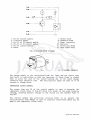
During recent monitoring of Service Warranty Claims/Returns, in particular problems
relating to Air Flow Meter Hoses split or adrift, and headlamp adjustment, investigations
have been impeded by incorrect warranty codes being quoted.
Will Dealers please note that for the above mentioned problems the correct codes to be
utilized are as follows:
Air Flow Meter Hose
Air Flow Meter Hose
Headlamp Unit
Adrift
Split
Adjusted
=
='
=
Jaguar Cars Limited
2F2 B
2F2 E
7J1 A
Jaguar Cars Limited 2005
ITEM 16
03
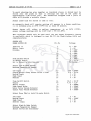
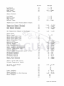
REPAIR OPERATION TIMES
XJ-S 3.6/XJ-SC 3.6
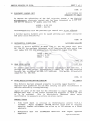
Service Times and Option Service Times for the new XJ-S 3.6 and XJ-SC 3.6 are quoted
below. There are no differences in Service Times or Option Service Times between the two
models.
·
INTERVAL
1,000
7,500
15,000
22,500
30,000
37,500
45,000
52,500
60,000
67,500
75,000
82,500
90,000
97,500
miles
miles
miles
miles
miles
miles
miles
miles
miles
miles
miles
miles
miles
miles
SERVICE TIME
OPTION SERVICE TIME
3.45 hrs
3.20 hrs
4.45 hrs
3.20 hrs
5.35 hrs
3.20 hrs
4.50 hrs
3.20 hrs
5.35 hrs
3.20 hrs
4.45 hrs
3.20 hrs
5.40 hrs
3.20 hrs
0.90
0.25
0.90
0.25
0.90
0.25
0.90
0.25
0.90
0.25
0.90
0.25
0.90
hrs
hrs
hrs
hrs
hrs
hrs
hrs
hrs
hrs
hrs
hrs
hrs
hrs
Use current Supplementary Job Sheets for these services.
No other Services Times or Option Services Times are affected.
12
ENGINE "GROAN" ON INITIAL START UP
5.3 MODELS
Reports have been received of an engine noise on V12 engines ~escribed as a "groan" on
initial start up when the engine is cold. This is a standard feature, although it may not
affect every engine. It is caused by the oil pump purging air out of the lubrication system
which cah enter the system after the engine has stopped.
It is not detrimental to the running/performance of the engine and disappears very quickly
after starting.
NOTE: Any noise which persists for a significant length of time should be investigated
further.
ITEM 18
12
'E' EMISSION ENGINES
SERIES Ill XJ6
MIDDLE EAST MARKETS (BAHRAIN, KUWAIT, LEBANON, OMAN, QATAR, SAUDI
ARABIA, UNITED ARAB EMIRATES)
To accommodate the introduction of the evaporative loss system detailed in Service Bulletin
JD 01/84 Item 01, all XJ6 vehicles supplied to Middle East markets are now fitted with
'E' emission specification engines. In addition to a thermal vacuum valve, and throttle edged
vacuum source for the evaporative loss system, 'E' emission engines also incorporate
standard compression pistons (Part No. EAC 2042).
'E' emission 6 cylinder engines were introduced for the above markets at VIN 380366.
Jaguar Cars Limited 2005
Sheet 2 of 3
SERVICE BULLETIN JD 03/84
ITEM 19
19
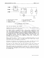
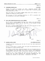
CRUISE CONTROL
SERIES Ill 4.2 EFI
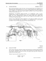
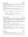
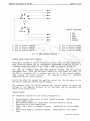
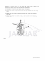
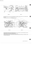
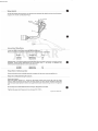
Would Distributor/Dealers please note that if they are involved w ith the installation of an
Econocruise after sales cruise control kit Part No. 2.5042 as specified for Jaguar Series Ill
4.2 EF I Models, it is ESSENTIAL that the instructions regarding the fitment of the Econocruise throttle lever, and bowden cable brackets, reference kit part number 236, are
followed carefully (See Fig. 1).
IMPORTANT: FOLLOWING INSTALLATION, IT IS ESSENTIAL THAT A FULL
OPE RATIONAL CHECK IS CARR lED OUT. THIS IS TO ENSURE THAT THE MOVEMENT OF THE ECONOCRUISE THROTTLE CABLE DOES NOT COME INTO
CONTACT WITH THE FUEL INJECTION FUEL RAIL HOSES, AS EXPLAINED IN THE
FITTING KIT INSTRUCTIONS.
SHOULD ANY PROBLEMS ARISE THROUGH A FAILURE TO COMPLY WITH THE
FITTING INSTRUCTIONS OR OTHERWISE, THE RESPONSIBILITY LIES SOLELY
BETWEEN THE DISTRIBUTOR/DEALER AND ECONOCRUISE LTD.
Fig 1
JS I 2 L. 2
ITEM 20
26
5.3 MODELS
RADIATOR HOSE
Several reports have been received of radiator hoses splitting on the above models, especially
the top hose. Investigations with the supplier have attributed th is to delamination of the
hose material, resulting in bursting of the hose. All suspect hoses have been removed from
production and U nipart stocks.
Radiator hoses are quality assured from VI N's:
373192 - Series I I I
113471 - XJS
Jaguar Cars Limited 2005
ITEM 21
26
WATER PUMP LEAKAGE
XJ6/SERIES Ill
Investigations into XJ6 water pump leakage have revealed a problem with the machining
of the seal seat in the water pump body, which could allow movement of the seal.
This has now been corrected and water pump seal location is assured from Engine Nos:
8L 146844-4.2
8A 14618 -3.4
7M 4766 - Limo
ITEM 22
44
SERIES 111/XJ6
BORG WARNER MODEL 66- SUN GEAR SHAFT
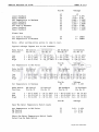
Further to Service Bulletin JD 03/83, detailing a material specification change of the sun
gear shaft from SAE 8620 to EN 368, the sun gear shaft sealing ring grooves are now shot
peened to relieve any possible stress points.
This modification was introduced at:
ENGINE NO.
TRANSMISSION NO.
8L 143470
SA 14592
6066 39459
6067 4284
MODEL
4.2
3.4
ITEM 23
82
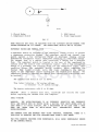
AIR CONDITIONING EVAPORATOR
SERIES Ill- XJS 'HE'
(AIR CONDITIONED MODELS)
Air conditioning units are now received from the supplier with the evaporator assembly
dehydrated and pressurised. Units to this condition were invoduced at VIN:
34 7244 - Saloon
108046- XJS
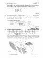
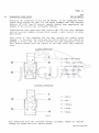
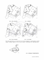
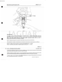
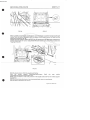
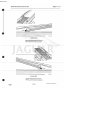
As a result of this improvement it has been necessary to modify the air conditioning unit
case to enable the evaporator unit to be fitted by the supplier without disturbing
the expansion valve assembly. Modifications have entailed the relocation of the evaporator/
expansion valve mounting plate fixings on the air conditioning unit case, see Fig. 1.
. Fig 1
c
A= Previous Condition
Jaguar Cars Limited 2005
Sheet
SERVICE BULLETIN JD 03/84
B = Latest Condition
3 Of 3
JSI-240
For parts replacement purposes, only evaporator/expansion valve assemblies to the latest
condition are available. Should replacement be required on vehicles prior to the above
VIN's, the following modification will apply. Evaporator/expansion valve assembly part
number remains unchanged AEU 1191.
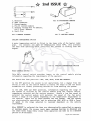
MODIFICATION PROCEDlJRE
1.
Following removal of the air conditioning assembly and subsequently the evaporator
unit, carefully cut off the metal flanges, see Fig. 1 (C).
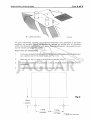
2.
Mark and dr ill the unit case to the dimensions detailed in Fig. 2.
3.
Following completion of procedures 1 and 2, ensure all swart is removed prior to
re-assembly.
4.
Locate new evaporator/expansion valve assembly and secure .
.--- - - -- - -·- ·- - -
- -- -- -- - - - --,
\
Fig 2
10mm
( 0.40in J
--r1
31mm
~I•
( 1.218in )
31mm
( 1.218in)
J SI-2J g
Jaguar Cars Limited 2005
ITEM 24
84
WINDSCREEN WASH/WIPE RESERVOIR GAP
XJS
The metal cap (Part No. GWW 968) for the windscreen wash/wipe reservoir was replaced by
a plastic cap (Part No. GWW 933) at VI N 108985. The plastic cap is available from Unipart
as a separate item. It is interchangeable with the metal cap up to VI N 110190, at which
time the windscreen wash/wipe reservoir and cap were replaced by a revised design.
ITEM 25
88
OIL PRESSURE TRANSMITTER
SERIES Ill & XJS 'HE'
Investigations into isolated instances of oil pressure gauge inaccurate readings, due to a
malfunction of the engine pressure transmitter unit, have identified the following fault.
During the manufacturing process, the transmitter lock screw is secured by "Parapan
Lacquer". Service units examined were found to have the internal diaphragm impregnated
with this lacquer, causing it to stick, and subsequently result in an inaccurate gauge reading.
Action to correct this production assembly fault fias been assured from supplier date code
Wk. 46.83, and progressively introduced from VIN's:
378920- Saloon
114671 - XJS
Jaguar Cars Limited 2005
JA~
Service Bulletin
FEBRUARY 1986
Dat e :
1 of 4
Shee t:
JD 02/86
Bull e tin:
ITEM: ll
00
S. III
AKM 9006 SERVICE MANUAL
An updated version of AKM 9006 Service Manual for S.III Models in Engl ish
language, is now available from Jaguar Parts Operations.
Unlike the
original Manual this is available only as a complete book.
Individual
books within the manual are not available separately.
Individual books for Edition 1 of the Ma nual may still be P¥rchased from
Jaguar Parts Operations while stocks la s t .
\
ITEM: 12
03
XJS CABRIOLET
PROPSHAFT REPAIR TIMES
Please add the following Repair Operation Times to you r XJS Repair Time
Schedules:
47-15-01
47-15-10
Propeller Shaft - Renew
Propeller Shaft - Overhaul
Vl 2
2.34
3.40
3.6
0.95
2.00
No other Repair Times are affected.
AKM
AKM
AKM
AKM
AKM
AKM
4412/83
4051/ 83
4446/83
4447/83
4448/83
4494/83
-
English
Italian
Dutch
French
German
Spanish
ITEM: 13
12
CRANKSHAFT FRONT SEAL
S.III XJ6 / LI MO
· A new crankshaft front sea 1 incorporat i ng a PTFE s e aling lip has
introduced on all 3.4 and 4 . 2 litre engines from Engine Nos :
been
SA 16541 - S.III 3.4
81 203238 - S.III 4 . 2
7M 5211
- Limo.
Jaguar Cars Limited
Jaguar Cars Limited 2005
The new seal is available under Part No. EAC 8815 and is supplied on a
mandrel which should not be removed until immediately prior to fitting the
seal.
This seal should now be used for all XK crankshaft front seal
replacements and should be fitted in conjunction with a new distance piece
(Part No. C40147) and '0' ring. When fitting the new seal please note the
following and refer to Repair Operation 12.21.14 in the Workshop Manual:
1
This seal is designed to operate without an oil flinger behind the
seal and it will therefore be necessary to remove this where fitted.
As the flinger cannot be withdrawn from the crankshaft with the timing
cover in place, cut into the notches with suitable metal shears and
discard the segments.
2
Fit the seal dry, as supplied, taking care to avoid contact with the
sealing lip.
Do not degrease the seal as this will damage the
material.
3
When fitting the new distance piece lubricate with clean engine oil.
Do not use grease.
4
When refitting the sump, apply a small bead of RTV sealant compound to
both sides of the sump face at the seal aperture joint, and torque the
sump fixing nuts and bolts to 20 nm (15 lb ft).
ITEM: 14
12
CYLINDER HEAD GASKET
S. I II XJ6 3. 4
To overcome instances of external coolant seepage from the cylinder
head/cylinder block joint, an improved cylinder head gasket, Part No.
EAC 8349, has been introduced on 3.4 litre engines from Engine No.
8A 16376.
ITEM: 15
12
ENGINE REAR MOUNTING SPRING
S .III XJ6
Due to instances of a 'knock' from the prop shaft area caused by excessive
movement of the transmission rear mounting, a revised gearbox rear
mounting spring has been introduced.
This spring, Part No. C45902/l is
now painted black and replaces the previous plastic coated spring, Part
No. C45902.
It was introduced at VIN 442669.
ITEM: 16
12
ENGINE STALL
S. II I XJ6 4. 2
ALL MARKETS EXCEPT USA, AUSTRALIA,
CANADA, JAPAN, SWEDEN, SWITZERLAND
Further
to
Service
Bulletin
JD
08/84
Item
65,
the
modification
incorporating the supplementary air valve to overcome engine sta 11, has
now been introduced on production built vehicles from VIN 443387.
Jaguar Cars Limited 2005
SHEET 2 of 4
SERVICE BULLETIN JD 02/86
ITEM: 17
19
S.III Vl2/XJS Vl2
(EMISSION "B" ONLY)
ELECTRONIC CONTROL UNIT
To improve the reliability of the fuel injection system, a new digitial
microprocessor electronic control unit has been introduced on S. III Vl2
and XJS Vl2 emission "B" models only from VINs:
441593 - S.III Vl2
127879 - XJS Vl2
Interchangeability with the previous type control unit is not affected.
A further Service Bulletin will be issued advising part number allocation
and parts stock availability.
ITEM: 18
51
S.III/XJS 3.6/LIMO
DIFFERENTIAL PINION SEAL
Further to Service Bulletin JD 08/85 Item 57, the new pinion seal, Part
No. JLM 527, has now been introduced on all remaining GKN axle ratios from
unit number 85N 5701 and progressively introduced at Jaguar from VINs:
129526 - XJS 3.6
446153 - S.III
200821 - Limo
ITEM: 19
76
S. III XJ6
GEAR LEVER GAITER
To prevent gear lever 1 sizzle' on manual transmission XJ6 vehicles, a
revised gear lever gaiter, incorporating a rubber 'O' ring and retaining
ferrule, was introduced on 1986 M.Y. vehicles.
This gaiter is available
under Part No. BBC 8602.
ITEM: 20
79
PAINT RECTIFICATION-CRAZING/CHECKING
ALL MODELS
This Bulletin has been prepared primarily to provide Jaguar Dealers/
Importers with guidelines for use when carrying out paint rectification on
vehicles affected by crazing/checking.
Jaguar are aware of the need for the refinisher to repair first time, any
damaged paint work, so the correct approach and diagnosis is vital if this
is
to
be achieved.
This
is
particularly
important where
major
rectification is necessary as errors can prove costly.
GENERAL POINTS
1
Film build depth is critical on thermo-plastic acrylic (T.P.A.)
finishes.
Jaguar recouunend 150-200 microns total film at original
exterior, however refinishers can allow up to 250 microns on a sound
substrate.
2
Refinishers
suppliers.
must
use
recommended
materials
from
Jaguar
approved
Jaguar Cars Limited 2005
United Kingdom and Europe:- Inmont, I.C.I., Ault and Wiberg, Sikkens,
Dupont, Berger, P.P.G. United Kingdom and Glasurit.
U.S.A. and Canada:and Dupont.
Inmont/Rinshed-Mason,
I.C.I/C.I.L.
Ltd,
Sikkens
Australia:- Spartan and Dulux
R.O.W:- Approved supplier materials from the above via importers or
local agents.
These materials may be marketed under an alternative
trade name.
3
Paint supplier data sheets must
viscosity,
application,
surface
temperatures.
be referred
preparation
to with regard to
and
spray
booth
DEFINITION:
Crazing/checking can be categorised into three types, of which one or two
may be present on a vehicle.
1
Fuel Crazing
Forms a local run pattern of fine crazing due to fuel spillage onto
newly applied paint.
2
Fine Cracking/Checking
Evident on early cars, emanating from around the front and rear
screens of direct glazed thermo-plastic acrylic (T.P.A.) vehicles.
Small areas of fine crazing/checking are usually apparent adjacent to
the cracking.
Material and process changes have eliminated this
problem.
3
General Crazing/Checking
Mainly affecting horizontal panels, this fault may develop in the post
This fault is
warranty period if the paint film deteriorates.
caused by excessive film build, incompatible materials, temperature
changes, etc.
DIAGNOSIS
1
Define the extent of the fault,
crazing.
i.e.
local, extensive, fine or heavy
2
Examine the film build thickness of the existing finish.
3
Take into consideration the vehi cle colour prior to deciding the
extent of rectification, e.g. to achieve a satisfactory colour match
on certain metallics, local repa i r may have to be extended to envelop
a section of the vehicle.
4
Where the crazing is severe define the depth by flatting loca lly and
examining with a magnifying glass.
5
ALWAYS REMEMBER THAT WHEREVER POSSIBLE THE ORIGINAL FINISH I.E.
ELECTROCOAT AND PRIMER-SURFACER SHOULD BE LEFT INTACT. WHERE A FAULT
IS SEVERE BUT CONFINED TO HORIZONTAL SURFACES, IT MAY BE ADVANTAGEOUS
TO SAND OFF TO A SOUND SUBSTRATE INSTEAD OF COMPLETELY STRIPPING TO
BARE METAL.
6
The alternatives to a complete strip should always
consideration when refinishing, as an incorrect process
metal will almost certainly promote future problems.
be given
from bare
Jaguar Cars Limited 2005
SERVICE BULLETIN JD 02/86
SHEET 3 of 4
RECTIFICATION
1
Local fine crazing/checking.
Pl200 wet flat, compound and polish.
2
Fine cracking/checking (around screens)
Where this fault is evident and emanates from the screen apertures,
remove the outer lace and wet flat with P800 to remove all traces of
the fault.
Apply an approved paint process to the affected areas.
NOTE: where the cracking affects the top of the aperture a complete
roof panel respray may be necessary .
3
Local Heavy Crazing (Fuel Spilliage etc)
Wet flat locally, P800, to remove the
paint process.
fault
and
apply an approved
4
Extensive Crazing affecting the colour coat.
Use one of two methods:
a) Wash cff the colour with acrylic thinners avoiding any spillage or
runs onto adjacent panels.
or
b) Sand off the colour mechanically finishing off with a P600-P800 wet
flat.
Following preparation apply an approved paint process.
5
Extensive Heavy Crazing of indeterminate depth.
a) Apply a chemical stripper to remove all paint to bare metal. NOTE:
strippers are most effective if used in two stages:
1. Colour Removal
2. Primer and surfacer removal.
CAUTION: DO NOT APPLY STRIPPER WITHIN 25mm of PANEL EDGES, CHANNELS,
GLASS OF TRIM FINISHERS.
b) Remove the paint with a scraper and/or steel wool.
c) Wash off the stripped vehicle with solvent (SBP 3 or similar)
activating with steel wool to remove any residues.
d) Flat off paint from the panel edges and around the finishers. Blow
off with an air gun and wash the complete vehicle with solvent.
e) Apply a phosphoric acid metal conditioner to the manufacturer
specifications . This will remove surface contamination and etch
the metal surface to assist paint adhesion. NOTE: this operation is
most important.
f) Wash off the activated conditioner with clean water and dry off
thoroughly with chamois leather and air gun.
g) Ensure the prepared surface remains uncontaminated by fingermarks
etc, and apply an approved 2 pack etch primer to the bare metal.*
h) It is essential that a suitable primer-surfacer is applied within
one hour of the etch-primer or blistering may occur.*
i) Following preparation apply an approved paint process.
*
NOTE: These operations must be carried out in a temperature controlled
spray booth.
Jaguar Cars Limited 2005
ITEM: 21
XJS
84
. PRE HE MODELS
WINDSCREEN WIPER MOTOR
Following the conversion on Pre XJS HE Models, of the windscreen wiper
system using Service Kit AEU 1731 and motor assembly AEU 1738 (Service
Bulletin JD 11 /8 1 Item 83 refers), several Dealers have experienced the
problem of the circuit fuse conti nually blowing.
Investigations have identified that certain AEU 1731 kits were equipped
with an incorrect adaptor harness which caused a short curcuit to occur
when fitted.
Parts stock of this component has now been checked and suspect stock
removed.
In the event that s tock may be held by Dealers, kits should b e
checked to ensure that the correct harne ss has been supplied.To clarify
this, Dealers should check the colours of the wiper motor plug connector
wires.
Correct Condition
-1
3
4
1)
Red Light Green
2)
Whit e Light Green
3)
Yellow Light Green
4)
Blue Lig ht Green
5)
Light Green
1)
White
2)
Red
3)
Yellow
JSI450
Incorrect Condition
- -1
3
4) = Brown
5
4
5)
Green
J SU.SO
Kits identified with the incorrect harne ss
through the normal Parts D.Y . Return System.
included,
should
be
returned
Jaguar Cars Limited 2005
SERVICE BULLETIN JD 02/86
SHEET 4 of 4
ITEM: 22
86
ALTERNATOR
S.III Vl2
A revised Al33-75 amp alternator and alternator
introduced on S . III Vl2 Models from VIN 425413.
The revised alternator incorporates
replaces the previous Lucar terminals.
a
single
harness
eyelet
have
connector
been
which
For introduction details on:- S.III XJ6 Air Con Models, Service Bulletin
JD 04/85 Item 30 refers.
XJS Vl2 models, Service Bulletin
JD 09/85 Item 69 refers.
ITEM: 23
88
SPEEDOMETER TRANSDUCER
S. III/XJS
Instances of electronic speedometer signal transducers becoming loose and
possibly detached from the transmission housing, have been identified in
Service .
Production procedures have now been corrected and security of the unit
assured from VINs:
444581 - S . III
128950 - XJS
To ensure tha t transducer units are secured correctly on vehicles prior to
the above vehicle identification numbers, Dealers will be requiried to
check all new vehicles at P.D.I. and those in service at the next service
interval.
The knurled locking ring may be GENTLY tightened using a suitable
adjustable spanner. Do not overtighten as this will result in damage to
the transducer unit.
Jaguar Cars Limited 2005
JA~
Service Bulletin
Date:
Sheet:
Bulletin:
JULY 1986
1 of 9
JD 07/86
ITEM: 45
17
EMISSION 'F'
AUSTRIA, GERMANY AND SWITZERLAND
S.III 4.2/ALL Vl2
To satisfy legislative market requirements a revised engine specificiation
for the above markets has been introduced. This incorporates an emission
type 'F' engine with stellite seat valves and emission equipment changes
to suit unleaded fuel.
A summary of the emission equipment by market is tabulated below:
Germany
S.III 4.2
S.III Vl2/XJS Vl2
A
Austria, Switzerland
S.III 4.2
S.III Vl2/XJS Vl2
X
X
A - Underfloor Catalyst
C - Air Injection
* - To rationalise build.
subsequent builds.
The engine idle
following values:
and
B
X
X
X
X
c
D
X
X
*
X
X
X
X
X
B - Downpipe Catalyst
D - Oxygen Sensor
Fitted to first cars only; not required on
ignition
setting
should
be
checked
against
S.III 4.2
Austria, Germany
and Switzerland
Idle speed 750 - 850 rev/min
Ignition Timing 16-18° BTDC at 800 rev/min
with vacuum disconnected
S.III V12/XJS Vl2
Austria, Germany
and Switzerland
Idle speed 650-850 rev/min.
Ignition Timing 15-17° BTDC at 3,000 rev/min
with vacuum disconnected
the
These changes have been introduced from engine numbers:
8L 209816 - S.III 4.2
7P 55737 - S.III Vl~
8S 43250 - XJS Vl2
Further details and part numbers will be issued as parts are available.
Jaguar Cars Limited
Jaguar Cars Limited 2005
ITEM: 46
74
ALLOY ROAD WHEELS
SIII/XJS
A small batch of vehicles fitted with alloy road wheels and Pirelli tyres,
recently despatched from the factory, are subject to reports of white
staining of the protective lacquer.
This has been caused by the solvent used by the supplier to clean the
wheel
prior
to application
of the balance weights not
being to
specification.
This staining should be removed at P.D.I. stage, by buffing the area with
a pad lightly moistened with Ethyl Methyl Ketone (MEK).
When using
adhered to:
this
chemical
the
following
precautions
MUST
be
strictly
*
Highly flamable - DO NOT USE whilst standing near a naked flame or
smoking.
*
DO NOT INHALE -
*
Avoid contact with the skin and eyes - wear protective clothing,
e.g. gloves, glasses, etc.
Only use in a well ventilated area.
ITEM: 47
76
SEAT BELT SLIDER BAR
XJS
To assist occupants with the fitting of XJS seat belts, Jaguar have
carried out a modification to the fixed anchorage point.
A bar has been
installed which is secured to the sill at its forward position and is
located in an aperture situated in the heel board panel at its rear
location.
The seat belt has a stitched loop which passes over the slider bar prior
to fitment into vehicle.
This loop allows fore and aft movement of the
seat belt to be achieved.
100% fitment to Coupe models is assured from VIN 131010.
The Cabriolet will also be fitted with this modification from early August
on 1987 M.Y. vehicles (introduction VIN to be advised).
NOTE: This is an Engineering Design modification and cannot be fitted to
pre-modification vehicles.
To fasten the seat belt pass a hand back along the sill, grasp the belt
and pull forward.
Transfer the belt to the other hand, pull across the
body and fasten in the normal manner.
ITEM: 48
80
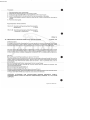
PLENUM GRILLE
The plenum grille is located by two push
illustration) located in two friction bushes.
S . III
fit
retention
pegs
(see
It is possible to damage the plenum grille using an incorrect method of
~emoval, i.e. levering the grille free at the extreme ends.
Jaguar Cars Limited 2005
SERVICE BULLETIN JD 07/86
SHEET 2 of 9
To avoid damage, use a screwdriver with a narrow blade covered with cloth
(preventing damage to grille paintwork ) , inserted at location A or B,
between the plenum grille and panel. Gently lever the grille forwa rd and
up until the retention peg is free of the bush.
JSI-t. 77
the above
complete removal.
Repeat
procedure
for
the
remaining retenti on
peg
location
to
I TEM: 49
82
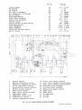
MK III AIR CONDITIONING UNIT
S.III Vl 2/XJS
Jaguar will b e introducing a new air conditioning system for the above
models
shortly.
The
followi ng
information
is
provided
to
allow
technicians to develop an early a ppreciation of its features and functions
prior to the release of further documentation.
The concept of this sophisticated air conditioning system ha s been
To a chi e ve this,
developed to increase performance and reliability.
mechanical components are kept t o a minimum.
ELECTRONIC CONTROL MODULE
The control module is a computer at the heart of which is a di g ital microprocessor.
It receives dat a signals from driver operated switches, the n
by comparing this data with data received from various tempera ture s e nsors
and feedback sensing devi c es, it calculate s the output volt a ges needed t o
ope rate the blower motors, flap s ervo motors, compressor and vacuum
solenoids to achieve the temperature requirement selected for the vehicle.
Although the control module c annot be r e paired i n service, a set of test
pins are accessible for testing the various circuits by the use of a
digital multimeter.
GREAT CARE MUST BE EXERCISED WHEN USING THE TEST
METER.
THE CONTROL MODULE WILL BE IRREPARABLY DAMAGED SHOULD ANY OF THE
TEST PINS BE MOMENTARILY SHORTED TOGETHER .
This technique should only be
used until the new Jaguar Diagnostic System is available, which is
designed to test Mk.III Air Conditioning full y and comprehensively.
Jaguar Cars Limited 2005
Jil!lt:ll.
6.
7.
8.
9.
10.
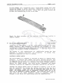
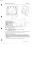
1. Upperfeed Back Potentiometer
2. Lowerfeed Back Potentiometer
3. Water Temp. Switch
4. Recirc. Vacuum Solenoid
5. Water Valve Vacuum Solenoid
Differential Temp Control
Temp. Demand Control
Temp. Demand Potentiometer
Condensate Drain Tube
Recirc. Solenoid Vacuum Restrictor
FIG 1 AIR CON UNIT LH SIDE
10
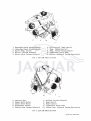
1.
2.
3.
4.
5.
Control Unit
Upper Servo Motor
Lower Servo Motor
Evaporator Sensor
Centre Vent Vacuum Solenoid
6.
7.
8.
9.
10.
Defrost Vacuum Solenoid
Mode Switch
Mode Control
Condensate Drain Tube
Centre Vent Solenoid Vacuum Restrictor
FIG 2 AIR CON UNIT RH SIDE
Jaguar Cars Limited 2005
SERVICE BULLETIN JD 07/86
SHEET 3 of 9
22
3
21
19
20
'
18
4~
17
5
6
---II·
16
!•
15
14
13
7
8
1
2
3
4
5
6
7
8
9
10
11
9
10
Control Module
Differential Temperature Control
Temperature Control Switch
Mode Control Switch
Ambient Temperature Sensor
In Car Temperature Sensor
Evaporator Temperature Sensor
Coolant Temperature Switch
Flap Feedback Potentiometer
Flap Feedback Potentiometer
Blower Motor Feedback
11
12
12
13
Blower Motor Feedback
High Speed Relay
Compressor Clutch
Blower Motor
Blower Motor
Servo Motor
Servo Motor
Defrost Vacuum Solenoid
Recirculation Flaps Solenoid
Centre V~nt Solenoid
Water Valve Vacuum Solenoid
14
15
16
17
18
19
20
21
22
FIG 3
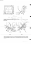
TEMPERATURE DISTRIBUTION SYSTEM
The air conditioning unit case consists of three parts, the rear of which
carries the evaporator, the front is then split in two to enable the
rotary flaps to be inserted.
The method used to achieve the required air temperature is known as a
series parallel system.
All the air into the unit passes through the
evaporator, then depending on the position of the flaps either passes
through the heater matrix to be heated, or bypasses the heater matrix
completely, or a combination of both to achieve the air temperature
required.
The system employs two flaps that are driven to the required
position (determined by the control system) by servo motors and gear box
assemblies.
The motor can rotate in either a clockwise or anti-clockwise
direction depending on the direction of current flow through the motor.
Jaguar Cars Limited 2005
J81 1U.
FIG 4 FULL HEATING
FIG 5 DEFROST
-.....'
-.. . -_,
'~"':-...
.
'--.!
FIG 6 FULL COOLING
FIG 7 AIR BLEND
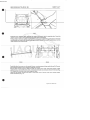
The flap positions are monitored by 2K2 ohm feedback potentiometers which
supply voltage signals to the control module indicating the flap postions.
FIG 8 FEEDBACK POTENTIOMETER
Jaguar Cars Limited 2005
SERVICE BULLETIN JD 07/86
*
2nd ISSUE*
SHEET 4 of 9
TEMPERATURE SELECTOR
The temperature requirement is selected by the setting of a 2K2 ohm
potentiometer which is coupled to the temperature control switch. 5 volts
is supplied to the potentiometer from pin 43 of the control module.
The
output voltage is from zero to 2.885 volts, which represents a range of
temperatures from 19° to 29°c (66 to 84°F).
The rotation of the
potentiometer is restricted internally to 180° travel.
TEMPERATURE SELECTOR SWITCH - AUTOMATIC OVERRIDE FUNCTION
Incorporated within the temperature selector switch is the facility
override the automatic function.
This enables the temperature to
manually selected and is achieved by pulling the left hand knob.
to
be
Engaging the manual override mode and dialling the temperat u re switch
within the range available, allows the occupants to select the desired
temperature
of
air
entering
the
passenger
compartment.
This
is
permanently maintained regardless of the ambient temperature.
TEMPERATURE DIFFERENTIAL CONTROL
The slider control can be used to adjust the temperature of the air being
delivered through the fascia end vents.
When the control is at the full right position, the air being delivered to
the fascia end vents will be slightly cooler than that at the footwell
vents.
Moving the control to the left,
fascia end vents, at the full
This control does not affect
effective during 'NORM' (normal)
reduces the temperature of the air to the
left position the air is at its coolest.
the set in-car t emperature and is most
operation of the ai r conditioning system.
When the system is in a heating mode,
the feet than to the face.
this control allows warmer air to
IOK ohm slide potentiometer used for this purpose is coupled to the
thumbwheel.
Its supply voltage is from pin 7 and the signal voltage is
then fed to pin 28 of the control module.
A
TEMPERATURE SENSORS
There are three temperature sensors fitted into the system, the ambient
temperature sensor, the in-car temperature sensor and the evaporator
temperature sensor. All three sensors are electrically identical, but the
evaporator
temperature sensor
is
physically different
and
is
not
interchangeable with the other two.
An input of 5 volts is supplied to the sensors from pin 43 of the control
module.
The temperature sensing voltage from the sensor is then fed back
into the control module.
At 0°C (3zOF) the sensing voltage should be
2.732 volts and with a temperature rise or fall of 1°C (1.8°F) the
sensing voltage should rise or fall by 0.01 volts; for example, if the
temperature should rise to 5°C (41°F) from zero, the voltage will rise
by 0.05 volts to 2.782 volts.
The sensor is a semi-conductor device similar to a zenor diode in as much
as it allows current to flow in reverse bias.
The current flow through
the device varies with temperature and is very accurate over a wide range.
The sensor as.sembly has a built in potentiometer which is preset and
should not be adjusted.
Jaguar Cars Limited 2005
2nd ISSUE
J82117
1. Resistor
Semi conductor
Potentiometer
Pin 43 control module
Sensing voltage Pin 43 ambient,
Pin 5 evap. sensors
6. Earth Pin.
FIG 10 EVAPORATOR SENSOR
2.
3.
4.
5.
FIG 11 AMBIENT SENSOR
FIG 9 SENSOR DIAGRAM
COOLANT TEMPERATURE SWITCH
A water temperature switch is fitted to the lower side of the heater inlet
pipe.
Its contacts are open at temperatures below 40°C, this prevents
the fans from operating until relatively hot coolant is flowing from the
engine.
JS21l9
FIG 12 COOLANT TEMPERATURE SWITCH
MODE CONTROL SWITCH
This main control switch provides inputs to the control
information regarding the requirements of the operator.
module
giving
The switch has five position:- OFF, LOW, AUTO, HIGH AND DEFROST.
In the OFF position the system is not operational, but a signal from the
switch is sent to the control module to ensure the flaps in the fan motor
assemblies are closed, preventing outside air from entering the system.
In the LOW, AUTO and HIGH positions, information regarding the range of
fan speeds is received by the control module from the control switch,
temperature selector and the various sensors.
Should a low fan speed be
selected the control module will maintain the speed of the fan motor
within a range of low speeds depending on the temperature requirement of
the vehicle.
There are no steps between the fan speeds.
The fan speeds
are electronically controlled, and by selecting LOW, AUTO or HIGH a level
of speed in the range selected is received dependent on the vehicle
requirement.
When DEFROST is selected the fans are electronically controlled to operate
at maximum speed, the screen vents open, maximum heating is obtained and
the lower level flaps fully close (this operation can take up to a maximum
period of 30 seconds).
Jaguar Cars Limited 2005
SERVICE BULLETIN JD 07/86
SHEET 5 of 9
SWITCH POSITIONS
A OFF
B LOW
C AUTO
D HIGH
E DEFROST
L------------------------------;~8
1. Pin l3 control
2. Pin 14 control
3. Pin 15 control
4. Pin 27 control
module
module
module
module
5. Pin 1
6. Pin 12
7. Pin 44
8. Pin 9
control
control
control
control
module
module
module
module
FIG 13 MODE CONTROL DIAGRAM
BLOWER MOTOR SPEED DRIVE CONTROL
Mounted in the outlet of the blower motor units are heatsink assemblies,
each of which consist of an interference suppres s or diode ( 11 Fig.l4) a
feedback isola tion diode (8 Fig.l4) and a power tra nsistor (9 Fig . l4) .
The unit is supplied with positive battery voltage via an ignition
controlled fuse. With the fan motor running at high speed the relay (12
Fig.l4) is energised with a voltage from pin 16 of the control module,
thus closing the relay contacts.
The negative circuit is therefore
completed via the relay contacts.
On all the other fan speeds the negative circuit for the fan motor is via
the power transistor and the control module.
The feedback diode (8 Fig.l4) enables the control module to sense the
voltage at the negative terminal of the fan motor and so calculate the
speed of the blower motor.
VACUUM SYSTEM
The components operated by the vacuum solenoids are : Defrost/Demist flaps which are held closed by vacuum . Identified by a
green supply tube.
2 . . Recirculation/Fresh air flaps which are held closed by vacuum.
Identified by a blue supply tube.
3. Centre vent, which is opened by vacuum. Identified by a black supply
tube.
4 . Water valve which is closed by vacuum. Identified by a red supply
tube.
1.
Jaguar Cars Limited 2005
2-..-------------~------------~
5--~------------~--------------~~
6~--------· _j
Je6 ·29?
1.
2.
3.
4.
5.
6.
Pin 16 control module
battery supply
Pin 22 or 33 control module
Pin 31 or 32 control module
Pin 45 control module
Earth
7.
8.
9.
10.
11.
12.
+
Blower motor
Feedback diode
Power transistor
Resistor
Protection diode
High speed relay
FIG 14 BLOWER MOTOR DIAGRAM
J82 115
FIG 15 VACUUM SOLENOID
The vacuum supply to the recir c ulate/fresh air flaps and the centre vent
have built in restrictors so that t he operation of these flaps is slowed
down to avoid the risk of the system hunting due to the rapid change
caused by fast operation time.
The recirculation flaps can take up to 30
seconds to change state.
COMPRESSOR CLUTCH CONTROL
The output from pin 20 of the control module is used to energise the
compressor clutch relay (2 Fig.l6) which will result in the relay contacts
closing, allowing battery voltage to the clutch via the thermal fuse (3
Fig.l6).
The control module has protec tion circuits built in to protect the
micro-processor from damage in case of incorrect connections which may be
made to the compressor clutch relay.
Jaguar Cars Limited 2005
SHEET 6 of 9
SERVICE BULLETIN JD 07/86
3
8
7-..-------------~
-
6
J86 299
1.
2.
3.
4.
Positive Battery Supply
Clutch Relay
Thermal Time Fuse
Compressor Clutch
5. Pin 20 Control Module
6. Superheat Switch
7. Negative Pin Control Module
FIG 1 6 COMPRESSOR CLUTCH DIAGRAM
HIGH SIDE LOW PRESSURE (HSLP) SWITCH
Together with the introduction of the Mk III unit, a new compressor clutch
protection system will be introduced.
The thermal fuse and superheat switch are deleted and replaced by a high
side low pressure switch (HSLP).
The superheat switch design was such
that it d e tected pressure drop and superheated r efrigerant vapour on the
low pressure line. The HSLP switch is designed to monitor pressure drop
on the high side line. At a low pressure condition of 25 psi
5 psi, the
HSLP switch contacts, which are normally closed, open circuit, thus
breaking the earth circuit to the compressor clutch coil;
resulting in
the clutch drive disengaging.
±
Where a definate fault is present in the air conditioning system e.g., low
refrigerant, restriction, etc., the HSLP switch will remain open circuit
until such time as the problem is corrected.
Following rectification and recharging of the system, the HSLP switch will
return to a closed state, once again completing the clutch circuit.
The need for the thermal fuse has been obviated with this system and
significant benefits are gained especially where a transient fault occurs.
This condition has been experienced in service, and in some instances has
resulted in vehicles being returned several times to a Dealer for the fuse
to be replaced; although at the time the air conditioning s y stem appeared
to be fault free.
Jaguar Cars Limited 2005
JB&-510
1. Clutch Relay
2. Compressor Clutch
3. HSLP Switch
4. Diode Suppression
FIG 17
SOME VEHICLES MAY STILL BE EQUIPPED WITH THE SUPEHEAT SWITCH/THERMAL FUSE
SYSTEM FOLLOWING MK III LAUNCH. THE OPERATIONAL DETAILS ARE AS FOLLOWS:
SUPERHEAT SWITCH AND THERMAL FUSE
A superheat switch is included in the compressor clutch circuit to provide
a compressor protection system.
The superheat switch and therma 1 fuse
guards against a low refrigerant charge or blockages causing extreme
superheated refrigerant vapour conditions resulting in compressor damage.
The thermal fuse is a sealed unit containing a heater and a meltable
fuse.
The superheat switch is located in the rear of the compressor in
contact with the suction side refrigerant vapour. With a low refrigerant
charge or a blockage, the pressure drops and the temperature rises.
This
condition closes the superheat switch contacts, which completes the
thermal fuse heater circuit, melts the fuse, disconnects the battery
supply to the compressor clutch winding and the thermal fuse heater.
The
compressor ceases to operate and damage from insufficient lubrication will
be avoided.
The thermal fuse melts at 157 to 182°C.
Time taken 2 minutes - 14V system voltage.
5.5 minutes - ll.SV system voltage.
The heater resistance, cold 8 to 10 ohms.
CAUTION:
After a thermal fuse melt, establish
before replacing the thermal fuse unit complete.
and
rectify
the
cause
FAULT FINDING
WARNING:
THE MICRO-PROCESSOR IS AN EXTREMELY SENSITIVE AND EXPENSIVE
UNIT, AND SHOULD ONLY BE TESTED USING A DIGITAL TYPE MULTI-METER WITH NO
LESS THAN A 3. 5 DIGIT DISPLAY, AND A RESISTANCE OF NO LESS THAN 2 MEGS
OHMS ANY OTHER FORM OF MULTI-METER WILL
IRREVERSIBLY DAMAGE
THE
MICRO-PROCESSOR.
THE CONTROL PINS ARE MOUNTED VERY CLOSE TOGETHER, THEREFORE, THERE IS A
HIGH RISK OF SHORTING TWO PINS TOGETHER WHEN USING A TEST PROBE.
TWO PINS SHORTED TOGETHER EVEN MOMENTARILY, WILL CAUSE IRREPARABLE DAMAGE
TO THE CONTROL MODULE.
Jaguar Cars Limited 2005
SHEET 7 of 9
SERVICE BULLETIN JD 07/86
To avoid shorting two pins together an insulated sleeve or shroud must be
fitted over the probe so that it overlaps the end of the probe by
approximately 3 mm (9.125 ins). The insulation stripped from a piece of
cable will provide a suitable sleeve.
Always allow time for servos to come to rest.
An automatic check will require setting all sensors to a known condition,
i e in workshop area at 24°C (75°F) for at least 30 minutes.
Sensor inputs will relate to ambient temperature, ie at
sensor voltage readings will be 2.97V (lmV = 1°C (33.8°F).
24°C
(7SOF),
This technique should only be used until the new Jaguar Diagnostic System
is available, which is designed to test Mk.III Air Conditioning fully and
comprehensively.
SYSTEM OFF
POWER SUPPLY ON
Pin No
Voltage
1
11 - 14V
9
10
38
45
44
12
19
2
0
0
0
0
0
0
10
To
Low Input
Clutch Output (Evap Sensor below 2.720V)
Medium Input
High Input
Defrost
13
20
14
15
27
150
0.6
3
3
3
-
350mv
11.4V
5V
5V
5V
From On/Off Switch
Output
Recirc output
High Speed Relay
Water Valve Vacuum Solenoid
Centre Vent Vacuum Solenoid
44
43
10.3 4.730 0 0 0 -
13.3V
5.2V
200mV
200mV
200mV
200mV
Ignition in
Recirc Input
Grounds:
2
6
From On/Off Switch
To ON/OFF Switch
Set in Manual by shorting pin
- 6V
- 40mV
- 40mV
- 40mV
- 40mV
- 40mv
- 12mV
- 13.3V
Ground
Select Low On Mode Switch
Maximum Temperature Demand
3
16
17
18
Select Norm (Med or Auto) On mode Switch
Low Input
Medium Input
High Input
Defrost Input
13
14
15
27
3 - 5V
150 - 350mV
3 -
3 -
sv
sv
Select High On Mode Switch
Maximum Temperature Demand
Ensure Servos Are Stationary
Jaguar Cars Limited 2005
Pin No
Low Input
Medium Input
High Input
Defrost Input
13
14
15
27
Voltage
- sv
- 5V
- 350mV
3
3
150
3
-
sv
Select Defrost
Low Input
Medium Input
High Input
Defrost Input
13
14
15
27
3 - 5V
3 - 5V
3 - sv
150 - 350mV
Temperature & Diff Potentiometer Ranges
Temperature
Temperature
Diff Demand
Diff Demand
Demand (Maximum)
Demand (Minimum)
(Maximum)
(Minimum)
Set Temperature Demand to Mid Range
Select Norm
Recirc Input
Servo Drive Lower Flap
Servo Drive Lower Flap
Servo Drive Upper Flap
Servo Drive Upper Flap
Recirc output
Reference voltage
Defrost Output
High Speed Relays
Lower Feedback Potentiometer
Upper Feedback Potentiometer
Coolant Temperature Input
Defrost Output
Clutch Output (Evaporator above 2.74SV)
RH Blower Feedback
LH Blower Feedback
RH Blower Control
LH Blower Control
Water Valve Solenoid
Centre Vent Solenoid
35
35
28
28
35
9
37
41
40
42
3
7
ll
16
29
2.665 0 4.7500 -
3.105V
200mV
5.250V
200mV
1.43 - l.45V
3 -
sv
4V
4V
4V
4V
0 - 500mV
2.875
2.895V
0
SOOmV
0
500mV
0.60
0.90V
30
l. 15
l.45V
21
11
20
260
460mV
500mV
13.3
13V
13V
33
22
32
31
17
18
0
10.3
10
10
0
0
o.sv
o.sv
0
0
500mV
500mV
Select Low On Mode switch
Minimum Temperature Demand
Set Diff to Mid Range
Servo Stopped
Lower Feedback
Upper Feedback
Set Temperature to Mid Position
Servo Stopped
28
37
40
41
42
29
30
35
37
40
41
2.45 - 2.55V
4V
4V
4V
4V
0 - 0.2V
0 - 0.2V
1.43 - 1.45V
4V
4V
4V
Jaguar Cars Limited 2005
SERVICE BULLETIN JD 07/86
SHEET 8 of 9
Pin No
42
29
30
35
29
30
28
29
30
Lower Feedback
Upper Feedback
Set Temperature to Maximum
Lower Feedback
Upper Feedback
Set Diff to Maximum
Lower Feedback
Upper Feedback
Voltage
4V
0.57 0.60 2.665 0.979
1.518
4.750 0.979 1.340 -
--
0.87V
0.9V
3 .lOSV
1.279V
1.818V
5.20V
1.279V
1.640V
Blower Test
Set Diff To Minimum
Set Temperature to Minumum
Note:
28
35
0 - 200mV
0 - 200mV
After setting allow servos to come to rest.
Typical voltage figures are in the brackets.
Mode Switch
Position
Low
Med
High
RH Control
Pin No 32
LH Control
Pin No 31
1 - 2V ( 1. 77V)
2 - 3V (2 28V)
1 - 2V (1.17V)
1 - 2V (1. 7V)
2 - 3V (2.27v)
1 - 2V ( 1.19V)
Low
Med
High
RH Control
Pin No 32
1 - 2V ( 1. 24V)
1 - 2V ( 1.4V)
2 - 3V (2.2V)
LH Control
Pin No 31
Low
Med
High
RH Control
Pin No 32
RH Feedback
Pin No 33
LH Feedback
Pin No 22
4 - 6V (5.63V)
3 - 5V (3.4V)
1 - 2V (1.27V)
Voltage
1.43 - 1.4SV
LH Feedback
Pin No 22
1 - 2V ( 1. 27V) 6.5 - 9V (8.7V) 6.5 - 9V (8.7V}
1 - 2V (1.41V) 6.9 - 9V (7.SV} 6.5 - 9V (7. SV)
2 - JV (2.2V} 3.0 - SV (4.1V) 3.0 - sv (4.0V)
Pin No
28
Set Temperature to Maximum
Mode Switch
Position
4 - 6V (5.8V)
3 - 5V (3. 7V)
1 - 2V (1.22V)
Pin No
28
Set Temperature to Mid Point
Mode Switch
Position
RH Feedback
Pin No 33
LH Control
Pin No 31
1 - 2V (1.67V) 1 - 2V (1.63V)
2 - 3V (2.17V) 2 - 3V (2.1V)
2 - 3V (2.3V) 2 - 3V (2.3V)
RH Feedback
Pin No 33
Voltage
2.88 - 3.10V
LH Feedback
Pin No 22
6.5 - 9V (6.25V) 6.5 - 9V (6.1V)
3.0 - sv (4.25V) 3.0 - sv (4.2V)
3.0 - sv (3. 7V) 3.0 - sv (3.5V)
Pin No
Voltage
Open The Water Temperature Switch Leads
Set Temperature to Mid Point
RH Control
LH Control
35
32
31
1.43 - 1.4SV
0 - o.sv
0 - 0.5V
Short the Water Temperature Switch Leads
Select Low On Mode Switch
Jaguar Cars Limited 2005
Pin No
Clutch Output
RH Control
LH Control
Set Diff to Minumum
Set Temperature to Minimum
Recirc Output
High Speed Relays
Water Valve Solenoid
Centre Vent Solenoid
Defrost output
Select Defrost On Mode Switch
High Speed Relays
Lower Feedback
Upper Feedback
Select Off On Mode Switch
Recirc Output
20
32
31
28
35
3
16
17
18
35
27
16
29
30
44
3
Voltage
9.3
1
1
0
0
9.3
0
9.3
9.3
0
150
9.3
2.709
1. 714
0
9.3
-
12.3V
2V
2V
200mV
200mV
12.3V
200mV
12.3
12.3
SOOmV
350mV
12.3V
3 .lOOV
2.014V
lV
12.3V
I
WK
12
22
10
<8
16
1
17
I
~
5
...
RL
r
24
Je~-
1
2
3
4
5
6
7
8
9
10
11
12
Control module
Ambient temperature sensor
Evaporator t~mperature sensor
In car temperature sensor
Recirculation vacuum solenoid
Defrost vacuum solenoid
Mode control switch
Water valve vacuum solenoid
High speed relays
Compressor clutch relay
Differential control
Coolant temperature switch
13
14
15
16
17
18
19
20
21
22
23
Joo
Centre vent vacuum solenoid
Lower servo feedback potentiometer
Upper servo feedback potentiometer
LH blower motor assembly
RH blower motor assembly
Temperature demand control
Upper servo
Lower servo
To compressor
To fuse
To fuse
FIG 18 AIR CONDITIONING WIRING DIAGRAM
Jaguar Cars Limited 2005
SHEET 9 of 9
SERVICE BULLETIN JD 07/86
ITEM: 50
84
S. III/XJS
WINDSCREEN WASHER FLUID
Between the months of October and April, commencing October 1986
windscreen washer fluid bottles will be filled with a solution giving
frost protection to -1soc.
This will apply to all markets except Canada which will continue to be
shipped dry between the above period.
The inclusion of fluid providing protection to -15°C is possible with
the introduction of new paint technology.
ITEM: 51
86
FUEL
TANK
S. III
ELEMENT/RECIRCULATION VALVE HARNESS
Due to service network demand, the fuel tank element and recirculation
solenoid valve link harness, Part No. DAC 1744, is now available through
the Parts Division.
DAC 1744 is routed/clipped beneath the fuel tank and is utilised on both
R/H and L/H side tank assemblies.
JSI-1.71
ITEM: 52
86
ELECTRIC AERIAL RELAY
XJS (FROM VIN 123281)
Instances of water entering past the boot lid seal have been experienced
on XJS models .
Action is being taken to prevent these leak paths and modifications will
be advised in a future Bulletin issue.
As a result of water entry, vehicles equipped with the Hirschmann Electric
Aerial Assembly, from VIN 123281 (JD-07 Item 55 refers), have experienced
contamination of the aerial relay, causing aerial operation to be affected .
To prevent this, relay assembly DAC 1820 has now been inverted.
This
ensures that the relay terminals are positioned downwards and are
therefore not vunerable to water splash. Introduced at VIN 132955.
Jaguar Cars Limited 2005
Vehicles in service prior to the safe VIN, where water
affected the aerial relay, may be modified accordingly:
ingress
has
a) Disconnect the battery and remove aerial trim panel.
b) Release the excess relay harness from the clips beneath the inner wing
panel.
c) Remove the relay from the mounting bracket lug, invert and relocate
onto lug.
d) Ensure the harness is routed as Fig. 1 and is clear of the mounting
bracket (A).
A
FIG 1
lll2F
Jaguar Cars Limited 2005
ScanFile 2002 v6.0 - Computer: SCAN004 - User: ADMIN - Date/Time: 28/08/02 1:02:19 PM - Page: 262/470
PAGE: BATCH
DATE: MARCH 1989
SHEET:
1 of7
REF:
JD 03 I 89
ERRATA
Bulletin JD 02/89, Section 19, Item 07. Modification procedure, Paragraph 19 should read:-
•
"19
Remove auxiliary air valve and replace with new unit supplied in kit. Repair Operation
19.20. 16. refers."
(Not 12.20.16. as stated). Pleaseamendyourcopyaccordingly.
NOTE: Bulletin JD 0 1/89 Item 01 Marelli Digital Ignition
Paragraph 1 of sheet 2 states that the high compression 12.5:1 will be discontinued.
This should read was discontinued and replaced by the standard 11.5: 1 compression
engine.
We apologise for any confusion caused and affirm that all engines fitted with Marelli Ignition
will run on unleaded fuel.
ITEM: 11
XJS 3.6/XJ6 2.9 & 3.6
03 REVISED REPAIR TIMES
•
•
Since the deletion of "drive in - drive out" allowance, all modifications issued in Service
Bulletins have now been revised. Please amend your Bulletins where applicable using the
following list:
SRONo.
MODEL
TIME
PREV.
NEW
82-91-05
XJ6 2.9/3.6 RHO
1. 70 hr
1.55 hr
82-91-05
XJ6 2.9/3.6 LHD
1.05 hr
0.90hr
86-91-14
86-91-13
30 91-01
76-91-84
XJ6 2.9/3.6
XJ6 2.9/3.6
XJ63.6CAT
XJ6 2.9/3.6
0.30 hr
0.45 hr
0.55 hr
0.85 hr
0.15 hr
0.35 hr
0.40 hr
0. 75 hr
76-91-63
76-91-14
76-91-15
76-91-16
76-91-67
XJ6 2.9/3.6
XJ6 2.9/3.6
XJ6 2.9/3.6
XJ6 2.9/3.6
XJS/XJ6 3.6
1.50 hr
0.30hr
0.30hr
0.75 hr
1.45 hr
1.40 hr
0.15 hr
0.20hr
0.60hr
1.30 hr
Jaguar Cars Limited
ITEM
Air Con/Heater 'in car'
sensor.
Air Con/Heater 'in car'
sensor.
Bonnet/Chassis Earth
Electric Aerial
Catalyst Heatshield Rattle
Sliding Panel Seal/
Adjustment.
Door Panel Resonance
Boot-Connector Rattle
Centre Console
Radio Panel Creaks
ZF Transmission 1-2 shift
quality.
Jaguar Cars Limited 2005
ScanFile 2002 v6.0 - Computer: SCAN004 - User: ADMIN - Date/Time: 28/08/02 1:02:19 PM - Page: 263/470
PAGE: BATCH
SRONo.
MODEL
TIME
PREV.
NEW
76-91-26
XJ62.9/3.6
0.65 hr
0.55 hr
76-91-25
76-91-19
XJ62.9/3.6
XJ62.9/3.6
0.25 hr
0.30hr
0.15 hr
0.15 hr
76-91-20
XJ62.9/3.6
0.25 hr
0.15 hr
76-91-21
XJ62.9/3.6
0.25 hr
0.10 hr
76-91-23
76-91-13
76-91-24
76-91-78
76-91-78
76-91-77
76-91-80
XJ62.9/3.6
XJ6 2.9/3.6
XJ62.9/3.6
XJ6 2.9/3.6 RHO
XJ6 2.9/3.6 LHD
XJ62.9/3.6
XJ62.9/3.6
0.45 hr
0.45 hr
0.25 hr
1.35 hr
1.55 hr
1.60 hr
2.00hr
0.35 hr
0.35 hr
0.10 hr
1.30 hr
1.50 hr
1.25 hr
1.90 hr
76-91-81
XJ62.9/3.6
0.60hr
0.50hr
76-91-72
76-91-83
76-91-64
19-91-08
XJ62.9/3.6
XJ62.9/3.6
XJ62.9/3.6
XJ62.9/3.6
0.55 hr
0.40hr
0.45 hr
1.00 hr
0.40hr
0.30hr
0.30hr
0.90hr
76-91-82
76-91-08
XJ6 2.9/3.6
XJS-C
0.30hr
1.85 hr
0.20hr
1. 75 hr
._
ITEM
Passenger SW Pack and
Ashtray Assy.
Door Wood Veneered Panels
Front Door Sill Button/
Bezel.
Rear Door Sill Button/
Bezel.
Coinbox-Driverside
U nderscuttle.
Rear Parcel Shelf
Sunroof
Sunvisor Vanity Mirror
Sanden Compressor Noise
Sanden Compressor Noise
Blower Motor Assy. Mod.
Front Windscreen
Condensation.
Front Windscreen
Condensation
Rear Tail Light
Oil Pressure Transmitter
Fuel Tank Element
Fuel Tank -Internal Hose
Clipping.
Fuel Filler Flap
Boot Ventilation
•
NOTE: No other Repair Times are affected.
ITEM: 12
57 P.A.S. RACK FIXINGS/TORQUE SETTINGS
XJ6
The torque settings quoted in the XJ6 2. 9/3.6 Service Manual for the rack mounting securing
nuts and bolts have been changed from 26-29 Nm to 45-55 Nm. Please ensure that all
Service staff are made aware of this change.
•
ITEM: 13
64/ REAR SUSPENSION CREAKS
XJ6 2.9/3.6
66
Investigation into noises emanating from the rear suspension has identified that a creak can
occur where the upper shock absorber assembly mounting bracket locates into the body
aperture. To eliminate further instances of this fault, a spacer has been fitted (Fig 1} on all XJ6
vehicles built from VI N 5 71642.
This spacer is now available via Parts Supply and may be used as a retrospective in-service fix
on vehicles with this fault.
Jaguar Cars Limited 2005
•
ScanFile 2002 v6.0 - Computer: SCAN004 - User: ADMIN - Date/Time: 28/08/02 1:02:20 PM - Page: 264/470
PAGE: BATCH
SHEET2of7
SERVICE BULLETIN JD 03 I 89
•
Rectification:
•
Referring to XJ6 Service Manual Pages 61-1 to 64-7 for non-ride level suspension or 66-9 to
66-10 for ride level suspension, displace road spring/ shock absorber assemblies. Fit spacer
BEC 1184 over shock absorber. Assemble upper mounting bracket (Ref to Fig 1) .
Reassemble suspension and road test vehicle.
NOTE: Road spring/ shock absorber assemblies should not be dismantled.
The operation numbers, descriptions and times for the above procedures are as follows:64-91-01 Rear Shock Absorber Upper Spacer Modification- 1. 15 hrs
66-91-08 Ride Levelling Strut Upper Spacer Modification- 1 . 70 hrs.
ITEM: 14
76 CLIP -INTERIOR DOOR HANDLE
XJ62.9/3.6
It has been established that extreme force applied to an interior door handle can cause the clip
securing the operating cable to become disconnected.
•
Whilst the clip is simple to refit, it is recommended that it should be replaced by fitment of a
new improved clip AGU 2678 RH andAGU 2679 LH which will remain in position .
The new clip should be fitted on a Complaint Only basis, using the Repair Operation Number
and Time allowance quoted in this Bulletin.
Jaguar Cars Limited 2005
ScanFile 2002 v6.0 - Computer: SCAN004 - User: ADMIN - Date/Time: 28/08/02 1:02:20 PM - Page: 265/470
PAGE: BATCH
Procedure:
-~=-=-=--=-:_____
1.
2.
3.
4.
5.
6.
_ _ _ _ _ _ _ _ __
.___
Remove the door trim veneer panel.
Separate the retaining clip from the operating cable.
Fit the new clip AGU 2678 RH or AGU 2679 LH to the interior handle.
Insert the cable end into the clip and lock the clip into position on the cable.
Operate the handle to ensure it does not foul the clip. Clear as required by relieving the
handle.
Refit the veneer panel.
Repair Operation Times as follows:
7 6-91-3 7 Door Remote Operating Cable Retaining Clip
Modification
0. 10 hrs
76-91-38 Door Remote Operating Cable Retaining Clip
-Vehicle Set- Modification
0. 40 hrs.
ITEM: 15
76 MECHANICAL FIXING OF FRONT SEAT SQUAB COVERS
•
XJ6 2.9/3.6
INTRODUCTION
A change in the method of securing the front seat squab trim covers to the squab foam/frame
is being introduced on XJ6 2.9/3.6 models. Introduction is progressive, achieving 100%
across all colour derivatives (in cloth and leather) by commencement of 19 8 9 MY build.
The new method eliminates the use of adhesives in favour of a mechanical fix. Future parts
supply of squab trim materials will be to the new design condition and it is therefore necessary
to describe how these materials may be fitted to pre-1989 MY models should the need arise.
METHOD
Remove the seat (XJ6 Service Manual- Section 76.70.01).
Place the seat on a bench (suitably covered to prevent damage to the seat facing). Remove the
lumbar support handwheel/escutcheon. Remove the seat recline handwheel/escutcheon
(manual seat only). Remove the recline tube side covers- two on powered seats, one on
manual seats.
Remove the squab back finisher, exposing all the trim cover fixings.
Remove the head restraint securing clip. Cut the ratchet strap to release the harness, and
remove the head restraint.
Remove the steel spring clips (A Fig 1).
Release the fabric tie ribbons (C Fig 1).
Release the adhered edge of the cover from the frame (8 Fig 1 ).
To fully release the cover. pass one hand between cover and foam support {at the areas shown
in A Fig 2) and VERY CAREFULLY ease the cover away from the foam.
•
CAUTION: ALTHOUGH THE COVER I FOAM SHOULD SEPARATE EASILY,
EXERCISE GREAT CARE TO PREVENT IRREPARABLE DAMAGE TO THE FOAM
SUPPORT.
Jaguar Cars Limited 2005
•
ScanFile 2002 v6.0 - Computer: SCAN004 - User: ADMIN - Date/Time: 28/08/02 1:02:21 PM - Page: 266/470
PAGE: BATCH
•
SERVICE BULLETIN JD 03 I 89
c
SHEET 3of7
A
8
8
B
•
JSI97l
B
FIG 1
FIG2
Obtain the following tools:
1 Air driven or electric hand drill.
2 Hammer and centre punch. ·
3 Pilot drill- maximum 2mm diameter.
4 HSS drill4mm diameter.
5 HSS drill7mm diameter.
6 Drill stop.
7 Measuring tape and scriber.
•
Drill4 x 4mm holes in the seat frame in the positions shown in Fig 3.
NOTE: Dimension A Fig 3 = 6mm.
Dimension B Fig 3 = 152mm .
Drill2 x 7 mm holes in the seat frame side in the positions shown in Fig 4.
NOTE: Dimension A Fig 4 39mm.
Dimension B Fig 4 = 25mm.
=
N.B. A kit is required to fit the new squab covers according to the following procedure. This
can be obtained from Jaguar Parts Supply by quoting Part No. JLM 1787.
PROCEDURE FOR DRILLING HOLES:
1 Refer to the relevant figure for hole size/location, mark and punch the hole centre.
2 Drill a pilot hole. NOTE: A pilot hole is necessary to prevent any possible frame damage, ie
bending, which may result from the excessive pressure required to drill a full size hole.
3 Open out the holes to full size. NOTE: When drilling the 7mm holes, set the drill stop to
allow the drill to penetrate 1 Omm ONLY. The drill MUST NOT be allowed to contact the
recline motor.
4 Ensure that no drilling swart/debris enters the gear recline mechanism .
•
Jaguar Cars Limited 2005
ScanFile 2002 v6.0 - Computer: SCAN004 - User: ADMIN - Date/Time: 28/08/02 1:02:21 PM - Page: 267/470
PAGE: BATCH
•
A
-B
=
©
i
©
D
0~[0
A
FIG3
•
FIG4
TRIMMING THE SQUAB USING MECHANICAL FIXINGS
Place the new squab cover on the bench. Trim off excess foam and piping where necessary
(Figs 5 and 6).
•
FIGS
FIG6
Attach fine, malleable draw wires to the yellow elasticated support cables (A Fig 7). Starting
at the top, feed the draw wires down through the 'calico' material tubes that are fixed to the
vertical inner edges of the squab cover (Fig 7). Leave approximately 200mm showing at the
upper end.
Jaguar Cars Limited 2005
•
ScanFile 2002 v6.0 - Computer: SCAN004 - User: ADMIN - Date/Time: 28/08/02 1:02:21 PM - Page: 268/470
PAGE: BATCH
SERVICE BULLETIN JD 03 I 89
•
SHEET4of7
FIG7
Feed the inner retainer cable through the upper horizontal 'calico' material tube. Feed the
yellow support cables through the inner retainer cable eyes (Fig 8).
Fit the cover to the foam squab, feed the 200mm of support cable through the slits in the foam
and through the holes in the rubber diaphragm (Fig 9). Locate the support cable hooks into the
upper frame 4mm holes (Fig 9).
•
•
DO
•
>51962
FIG8
FIGS
Carefully align the cover over the squab/frame. ensuring a good shape and tailored fit. Ensure
that the head restraint/ cover holes are aligned correctly.
Pull the draw wires/support cables around the recline pivot tube. Hold one support cable
under tension, remove the draw wire, and locate the hook into the lower frame 4mm hole (Fig
10). Repeat for the other draw wire/support cable.
Feed the harnesses through the holes in the lower cover. Secure with new ratchet straps
where necessary (Fig 11 ).
•
Jaguar Cars Limited 2005
ScanFile 2002 v6.0 - Computer: SCAN004 - User: ADMIN - Date/Time: 28/08/02 1:02:22 PM - Page: 269/470
PAGE: BATCH
FIG 10
FIG 11
Fit the side borders into position and align the 7 mm holes. Secure with 'fir tree' plastic studs
(Fig 12).
Fit double-sided tape to the pivot flanges (Fig 13).
FIG 12
FIG 13
•
•
Remove the backing from the tape and position the cover lower trim onto the tape. Secure the
plastic retainer onto the frame flange (Fig 14).
Secure the cover to the frame using steel clips {Fig 15).
NOTE: Spacing of clips is determined by a series of small holes in the cover material. Locate
the clips at these holes.
Jaguar Cars Limited 2005
•
ScanFile 2002 v6.0 - Computer: SCAN004 - User: ADMIN - Date/Time: 28/08/02 1:02:22 PM - Page: 270/470
PAGE: BATCH
•
•
SERVICE BULLETIN JD 03 I 89
SHEET 5of7
FIG 14
FIG 15
Place a suitable support block on the bench. Cover the block to prevent damage to the seat
facing. Place the seat on the bench with the support block directly below the relief line (the
relief line is arrowed in Fig 16).
Position the outer retainer cable as shown in Fig 16. Press down the diaphragm until the inner
retainer cable (inside the 'calico' tube) meets the outer retainer cable. Secure both cables with
'hog rings' (Fig 16).
•
(
JSI9H
FIG 16
•
Refit the head restraint. Refit the squab back finisher.
Refit
the
lumbar
support
handwheel/escutcheon.
Refit
the
seat
recline
handwheel/escutcheon (manual seat only).
NOTE: Use a bradawl to mark hole positions in the squab side cover for the lumbar support
escutcheon
Refit the recline tube side covers- two on powered seats, one on manual seats .
Refit the seat to the vehicle 76. 70.01.
Jaguar Cars Limited 2005
ScanFile 2002 v6.0 - Computer: SCAN004 - User: ADMIN - Date/Time: 28/08/02 1:02:23 PM - Page: 271/470
PAGE: BATCH
REPAIR OPERATION TIMES
ELECTRICALLY OPERATED FRONT SEAT SQUAB MECHANICALLY FIXED COVER RENEW:
S.R.O. 76 . 70. 15. Time allowance- 1.45 hours.
•
MANUALLY OPERATED FRONT SEAT SQUAB MECHANICALLY FIXED COVER- RENEW:
S.R.O. 76. 70.25. Time allowance- 1.40 hours.
ELECTRICALLY OPERATED FRONT SEAT SQUAB ADHESIVE FIXED COVER- RENEW
USING MECHANICALLY FIXED COVER:
S.R .O. 76.91.29. Time allowance-1.65 hours.
MANUALLY OPERATED FRONT SEAT SQUAB ADHESIVE FIXED COVER- RENEW USING
MECHANICALLY FIXED COVER:
S.R.O. 76.91.28. Time allowance- 1.60 hours.
ITEM: 16
77 RECOMMENDED TREATMENT OF ELECTRONIC CONTROL
DEVICES IN AN ACCIDENT REPAIR
ALL MODELS
•
Electronic components are manufactured and designed to withstand damage or stress which
may arise during the manufacture and fitment to the vehicle.
Similarly, electronic control devices are positioned in or on the vehicle so as to survive most
accidents relatively undamaged.
The replacement of electronic control devices after an accident is therefore only necessary
when one or more of the following criteria are met:1
2
3
4
The housing is damaged or distorted
The mounting position or bearing surface is damaged or distorted.
The harness connector is damaged or corroded as a result of moisture.
The vehicle self-diagnosis facility or functional test indicates a fault.
ITEM: 17
77 BODY REPAIR- WELDING/BRAZING PRECAUTIONS
••
ALL MODELS
Due to the sensitive nature of certain electrical/electronic components on XJ6/XJS/ SIII,
essential precautions are necessary before carrying out welding or brazing.
1 DISCONNECT THE BATTERY BEFORE CARRYING OUT ANY BODY REPAIR WORK.
OBSERVE HEALTH AND SAFETY PRECAUTIONS.
2 Electric Arc Welding:
CAUTION: UNDER NO CIRCUMSTANCES MUST ELECTRIC ARC WELDING
EQUIPMENT BE USED ON JAGUAR VEHICLES.
Due to the high voltages produced, electric arc welding can cause irreparable damage to
the microprocessor/ECU controlled systems; therefore, this method of body repair must
not be used.
Jaguar Cars Limited 2005
•
ScanFile 2002 v6.0 - Computer: SCAN004 - User: ADMIN - Date/Time: 28/08/02 1:02:23 PM - Page: 272/470
PAGE: BATCH
SERVICE BULLETIN JD 03 I 89
SHEET 6of7
~--------~3~B~e~sGisut~a~n~c~e~S~p~o~tLJVV~eulduiun~g-·____________________________________________________
Resistance spot welding can only be carried out on bare metal. It is assumed, therefore,
that all trim and electrical components in the locality of the repair will have been removed
prior to panel removal/replacement. It is, however, the responsibility of the technician to
ensure that ALL sensitive electrical/electronic components in the locality of the repair are
disconnected and removed before commencing work.
4 MIG welding I brazing {including MIG plug I tack I seam I butt welding):
As with resistance spot welding, MIG welding and brazing will only be carried out when all
trim and electrical components have been removed, prior to painting. Again, it is
recommended that ALL sensitive electrical/electronic components in the locality of the
repair are disconnected and removed before commencing work.
Always observe Health and Safety precautions (see the relevant Service Manual, Section 7 7Body Repair). These methods of welding and brazing are the only ones recommended by
Jaguar Cars ltd.
•
ITEM: 18
84 WIPER MOTORS
XJS
To improve the wiper system performance on XJS models, a new wiper motor has been
introduced from VI Ns:152511 (RHD)
154405 (LHD)
Interchangeability between the previous wiper motor and the new system is affected. Should
it become necessary to replace the earlier motor, a conversion is possible utilising the parts
listed and following the detailed procedure. (For information on the earlier wiper motor
availability and supersession details, please refer to Parts Technical Information Volume J8
Number J 1, January 1989 Item 1).
Parts Required:
•
RHO Part No
DAC5504
DAC6053
DAC6148
DAC6150
Description
Wiper Motor/Grille Assembly
Intermittent Wipe Relay (Green Case)
Wiper Arm RH Crank (Driver}
Wiper Arm RH Straight (Passenger)
LHDPartNo.
DAC5505
DAC6053
DAC6149
DAC6150
Wiper Motor/Grille Assembly
Intermittent Wipe Relay (Green Case)
Wiper Arm LH Crank (Driver}
Wiper Arm LH Straight (Passenger)
A labour allowance of 1.45 hrs may be claimed, quoting Repair Operation No. 84-91-04 and
Complaint Code 7KA-B.
Modification Procedure:
•
Disconnect battery negative lead .
Jaguar Cars Limited 2005
ScanFile 2002 v6.0 - Computer: SCAN004 - User: ADMIN - Date/Time: 28/08/02 1:02:23 PM - Page: 273/470
PAGE: BATCH
--------~VV~i~p~e~r~S~w~it~c=h~-------------------------------------------------------------~
Access the wiper column switch, cut and remove the black (B) cable from the switch harness
at points 'A' and 'B' as indicated in Fig 1.
•
FIG 1
Intermittent Wipe Relay:
Locate the intermittent wipe relay (see Service Manual}.
Remove and replace with the new relay (green case} Part No. DAC 6053.
Model
Manual Ref
Key
3.6 RHO
3.6 LHD
86A56/57
86A58/59
35
23
(Please Note: 3.6 LHD key references Page 86A 58 are printed incorrectly; to obtain correct
locations, move all key descriptions up one number. Key 1 "air pump" is deleted. Key
reference 23 detailed above is corrected reference).
5.3RHD
86A60/61
5.3tHD
86A62/63
•
43
15
VViper Motor I Grille Assembly:
Remove the old motor and grille assembly, replace with the new motor and grille unit.
VViper Arm I Blade Setting Procedure:
Reconnect battery.
With the ignition switch 'on', switch on the wiper system and switch off with the wiper
switch. (This procedure ensures that the wiper motor is in the 'parked' position}. Note that
with the new wiper system, there is no suppressed wiper blade parking. Switch the ignition
off.
Fit the wiper arms and blades as shown in Fig 2, Diagrams (C) and (D).
Tighten the wiper arm fixing nut(s) to a torque of 9 - 10 N m.
Jaguar Cars Limited 2005
•
ScanFile 2002 v6.0 - Computer: SCAN004 - User: ADMIN - Date/Time: 28/08/02 1:02:24 PM - Page: 274/470
PAGE: BATCH
SERVICE BULLETIN JD 03 I 89
•
SHEET 7of7
JS1·103t.
DIAGRAMC
Passenger side RH Drive shown.
LHD is symmetrically opposite.
•
JSl·l033
DIAGRAMD
•
Driver's Side LH Drive shown
RHD is symmetrically opposite.
1888F
FIG2
Jaguar Cars Limited 2005