1
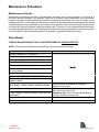
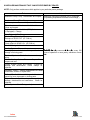
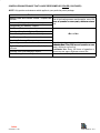
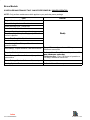
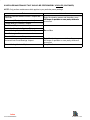
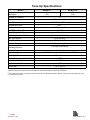
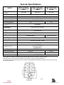
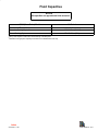
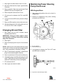
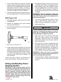
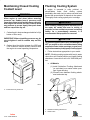
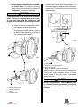
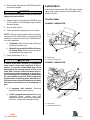
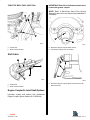
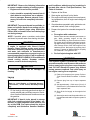
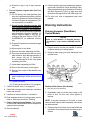
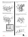
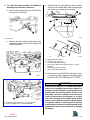
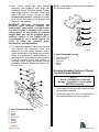
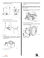
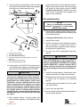
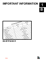
IMPORTANT INFORMATION
MAINTENANCE
Index
1
B
Table of Contents
Page
Maintenance Schedules . . . . . . . . . . . . . . . . . . . 1B-1
Maintenance Intervals . . . . . . . . . . . . . . . . . . 1B-1
Alpha Models . . . . . . . . . . . . . . . . . . . . . . . . . 1B-1
Bravo Models . . . . . . . . . . . . . . . . . . . . . . . . . 1B-4
Tune-Up Specifications . . . . . . . . . . . . . . . . . . . 1B-7
Fluid Capacities . . . . . . . . . . . . . . . . . . . . . . . . . . 1B-9
20-Hour Break-In Period . . . . . . . . . . . . . . . 1B-10
Fuel, Oil, Fluid, and Coolant Specifications . 1B-10
Fuel . . . . . . . . . . . . . . . . . . . . . . . . . . . . . . . . 1B-10
Crankcase Oil . . . . . . . . . . . . . . . . . . . . . . . . 1B-12
Power Steering Fluid . . . . . . . . . . . . . . . . . . 1B-13
Coolant for Closed Cooling System . . . . . 1B-13
Maintaining Crankcase Oil Level . . . . . . . . . . 1B-13
Overfilled Engine Crankcase . . . . . . . . . . . 1B-13
Checking Engine Oil Level/Filling . . . . . . . 1B-13
Changing Oil and Filter . . . . . . . . . . . . . . . . . . . 1B-14
Maintaining Power Steering Pump
Fluid Level . . . . . . . . . . . . . . . . . . . . . . . . . . . . . 1B-14
With Engine Warm . . . . . . . . . . . . . . . . . . . . 1B-14
With Engine Cold . . . . . . . . . . . . . . . . . . . . . 1B-15
Filling and Bleeding Power Steering System 1B-15
Maintaining Closed Cooling Coolant Level . . 1B-16
Flushing Cooling System . . . . . . . . . . . . . . . . . 1B-16
Lubrication . . . . . . . . . . . . . . . . . . . . . . . . . . . . . 1B-18
Throttle Cable . . . . . . . . . . . . . . . . . . . . . . . . 1B-18
Shift Cable . . . . . . . . . . . . . . . . . . . . . . . . . . . 1B-19
Engine Coupler/U-Joint Shaft Splines . . . 1B-19
Audio Warning System . . . . . . . . . . . . . . . . . . . 1B-20
Maintenance . . . . . . . . . . . . . . . . . . . . . . . . . 1B-20
Cold Weather or Extended Storage . . . . . . . . 1B-20
Precautions . . . . . . . . . . . . . . . . . . . . . . . . . . 1B-20
Layup . . . . . . . . . . . . . . . . . . . . . . . . . . . . . . . 1B-21
Draining Instructions . . . . . . . . . . . . . . . . . . . . . 1B-22
Draining Seawater (Raw-Water)
Cooled Models . . . . . . . . . . . . . . . . . . . . . . 1B-22
Draining Seawater Section of Closed
Cooled (Coolant) Models . . . . . . . . . . . . . . 1B-25
Recommissioning . . . . . . . . . . . . . . . . . . . . . 1B-27
Index
1B-0 - MAINTENANCE
90-823226--1 996
Maintenance Schedules
Maintenance Intervals
Maintenance intervals and the tasks to be performed, as shown in this current schedule, or as found in a
previously printed schedules, are generally based on an average boating application and environment.
However, individual operating habits and personal maintenance preferences can have an impact on the
suggested intervals. In consideration of these factors, MerCruiser has adjusted some maintenance intervals and
corresponding tasks to be performed. In some cases, this may allow for more individual tasks to be performed
in a single visit to the serving dealer, rather than multiple visits. Therefore, it is very important that the boat owner
and servicing dealer discuss the current Maintenance Schedule and develop appropriate maintenance intervals
to coincide with the individual operating habits, environment, and maintenance requirements.
Alpha Models
SCHEDULED MAINTENANCE THAT CAN BE PERFORMED BY OWNER/OPERATOR
NOTE: Only perform maintenance which applies to your particular power package.
Task
Interval
Engine Crankcase Oil - Check level
Closed Cooling Coolant - Check level
Power Steering Fluid - Check level
Stern Drive Unit Oil - Check level
Battery - Check level and inspect for damage
W kl
Weekly
Fuel Pump Sight Tube (If so Equipped) - Check that
no fuel is present
Power Trim Pump Oil - Check level
Anodes - Inspect for erosion
Gear Housing Water Pickups - Check for marine
growth or debris
Drive Belt(s) - Inspect condition and check tension
Every 100 hours of operation or 120 days.
Whichever occurs first.
Saltwater Use: Every 50 hours of operation or 60
days Whichever occurs first.
days,
first
Power Package - Exterior Surfaces - Spray with rust Freshwater Use: Every 100 hours of operation or
preventative
120 days, Whichever occurs first.
Propeller Shaft - Lubricate
Power Package Exterior Surfaces - Clean and paint
Once a year
Cooling System - Flush seawater section
Saltwater Use: After every use.
Index
90-823226--1 996
MAINTENANCE - 1B-1
SCHEDULED MAINTENANCE THAT CAN BE PERFORMED BY DEALER
NOTE: Only perform maintenance which applies to your particular power package.
Task
Seawater Pickup Pump - Disassemble and inspect
Interval
Whenever insufficient seawater flow is suspected.
(If operating temperature exceeds normal range.)
Crankcase Oil and Filter Change
Ignition system - Clean and Inspect condition.
Flame Arrestor and Crankcase Ventilation Hose Clean and Inspect.
Positive Crankcase Ventilation (PCV) Valve
(If Equipped) - Change
Stern Drive unit Oil - Change
Gimbal Ring Clamping Screws
Retorque to 50-55 ft. lb. (67-74 N·m)
Rear Engine Mounts
Check torque to 30-40 ft. lb. (47-54 N·m)
Gimbal Bearing - Lubricate
Cooling System - Clean and Inspect
Steering System - Lubricate and inspect for loose, End
E d off fifirst b
boating
i season and
d thereafter,
h
f
every 100
damage or missing parts.
hours of operation or once yearly, whichever occurs
first
Electrical System - Check for loose or damaged first.
wiring.
Closed Cooling System Pressure Cap - Clean,
inspect and test .
Cooling System Hoses and Clamps - Inspect for
damage and deterioration. Check clamps for
tightness.
Continuity Circuit - Check components for loose
connections, broken or frayed wires.
Shift and Throttle Cable and Linkage - Lubricate and
inspect for loose, damaged or missing parts.
Engine Exhaust System - Inspect externally for
damage, deterioration and restrictions. Check for
tightness.
Ignition System - Check Timing and adjust as needed.
Index
1B-2 - MAINTENANCE
90-823226--1 996
SCHEDULED MAINTENANCE THAT CAN BE PERFORMED BY DEALER (CONTINUED)
NOTE: Only perform maintenance which applies to your particular power package.
Task
Interval
Steering Head and Remote Control - Inspect and
End of first boating season and thereafter, every 100
lubricate.
hours of operation or once yearly,
yearly whichever occurs
Carburetor (If Equipped) - Inspect and adjust.
first.
Throttle Body (EFI Models) - Inspect.
Fuel Filters - Replace.
Quicksilver Mercathode System - Test output.
Closed Cooling Coolant - Test for Alkalinity
Once
a Year
O
Y
Heat Exchanger - Clean seawater section.
Drive Unit Bellows and Clamps - Inspect.
Engine Alignment - Check.
End of first boating season and thereafter,
Saltwater Use: Every 300 hours of operation or once
Engine Coupling Universal Joint Shaft Splines yearly, whichever occurs first
Lubricate.
Freshwater Use: Every 300 hours of operation or
Universal Joint Cross Bearings- Inspect.
once every two years, whichever occurs first.
Closed Cooling Coolant - Replace.
Every Two Years
Index
90-823226--1 996
MAINTENANCE - 1B-3
Bravo Models
SCHEDULED MAINTENANCE THAT CAN BE PERFORMED BY OWNER/OPERATOR
NOTE: Only perform maintenance which applies to your particular power package.
Task
Interval
Engine Crankcase Oil - Check level
Closed Cooling Coolant - Check level
Power Steering Fluid - Check level
Stern Drive Unit Oil - Check level
Battery - Check level and inspect for damage
W kl
Weekly
Fuel Pump Sight Tube (If so Equipped) - Check that
no fuel is present
Power Trim Pump Oil - Check level
Anodes - Inspect for erosion
Gear Housing Water Pickups - Check for marine
growth or debris
Drive Belt(s) - Inspect condition and check tension
Every 100 hours of operation or 120 days.
Whichever occurs first.
Saltwater Use: Every 50 hours of operation or 60
days, Whichever occurs first.
Power Package - Exterior Surfaces - Spray with rust Freshwater Use: Every 100 hours of operation or
preventative
120 days, Whichever occurs first.
Propeller Shaft - Lubricate
Power Package Exterior Surfaces - Clean and paint
Once a year
Cooling System - Flush seawater section
Saltwater Use: After every use.
Index
1B-4 - MAINTENANCE
90-823226--1 996
SCHEDULED MAINTENANCE THAT SHOULD BE PERFORMEDBY A DEALER (CONTINUED)
NOTE: Only perform maintenance which applies to your particular power package.
Task
Seawater Pickup Pump - Disassemble and inspect
Interval
Whenever insufficient seawater flow is suspected.
(If operating temperature exceeds normal range.)
Crankcase Oil and Filter Change
Ignition system - Clean and Inspect condition.
Flame Arrestor and Crankcase Ventilation Hose Clean and Inspect.
Positive Crankcase Ventilation (PCV) Valve (If So
Equipped) - Change
Stern Drive unit Oil - Change
Gimbal Ring Clamping Screws - Retorque to 40
ft. lb. (54 N·m)
Rear Engine Mounts - Check torque to 30-40 ft. lb.
(47-54 N·m)
Gimbal Bearing - Lubricate
Cooling System - Clean and Inspect
Engine Alignment - Check
Engine Coupling Universal Joint Shaft Splines Lubricate
Steering System - Lubricate and inspect for loose,
damage or missing parts.
End
E
d off first
fi boating
b i season and
d thereafter,
h
f
every
100 hours of operation or once yearly,
yearly whichever
occurs first.
Electrical System - Check for loose or damaged
wiring.
Cooling System Hoses and Clamps - Inspect for
damage and deterioration. Check Clamps for
tightness.
Closed Cooling System Pressure Cap - Clean,
inspect and test .
Continuity Circuit - Check components for loose
connections, broken or frayed wires.
Shift and Throttle Cable and Linkage - Lubricate
and inspect for loose, damaged or missing parts
Engine Exhaust System - Inspect externally for
damage, deterioration and restrictions. Check for
tightness.
Ignition System - Check Timing and adjust as
needed.
Index
90-823226--1 996
MAINTENANCE - 1B-5
SCHEDULED MAINTENANCE THAT SHOULD BE PERFORMEDBY A DEALER (CONTINUED)
NOTE: Only perform maintenance which applies to your particular power package.
Task
Steering Head and Remote Control - Inspect and
Lubricate.
Carburetor (If Equipped) - Inspect and adjust.
Interval
End of first boating season and thereafter, every
100 hours of operation or once yearly,
yearly whichever
occurs first.
Throttle Body (EFI Models) - Inspect
Fuel Filters - Replace
Quicksilver Mercathode System - Test output.
Closed Cooling Coolant - Test for Alkalinity
O
Once
a Year
Y
Heat Exchanger - Clean seawater section.
Drive Unit Bellows and Clamps - Inspect
Universal Joint Cross Bearings- Inspect
Closed Cooling Coolant - Replace
End of first boating season and thereafter, every
200 hours of operation or once yearly, whichever
occurs first.
Every Two Years
Index
1B-6 - MAINTENANCE
90-823226--1 996
Tune-Up Specifications
MODEL
Propshaft Horsepower Ratings
(Kilowatts) 1
Number Of Cylinders
MCM 4.3 LX
155
(115)
175
(130)
6
Displacement
262 Cu. In. (4.3L)
Bore/Stroke
4.00/3.48 (101.6/88.4 mm)
Compression Ratio
9.3:1
Compression Pressure
Idle RPM In Neutral
MCM 4.3L
180 PSI (1241 kPa)
2
650-700
Max RPM (at W.O.T.)
4400-4800
Oil Pressure (at 2000 RPM)
30-55 PSI (207-379 kPa)
Min. Oil Pressure
4 PSI (28 kPa)
Fuel Pump Pressure
3-7 PSI (21-48 kPa)
Electrical System
12 Volt Negative (–) Ground
Min. Battery Cold
Cranking Amperes
375 cca/475 mca/90 Ah
Firing Order
1-6-5-4-3-2
Spark Plug Type
AC-MR43T / Champion RV15YC4 / NGK BR6FS
Spark Plug Gap
Timing Thunderbolt IV Models
.040 In. (1 mm)
3
8° BTDC
Thunderbolt V Models 3
10° BTDC
Preliminary Idle Mixture
1-1/4 Turn
Thermostat
1
2
143° F (62° C)
Power Rated in Accordance with NMMA (National Marine Manufacturers’ Association) rating procedures.
Measured using an accurate service tachometer and fuel injection engine at operating temperature.
3 Timing must be set using a special procedure as outlined in the appropriate Service Manual. Timing cannot be properly set using
the conventional method.
Index
90-823226--1 996
MAINTENANCE - 1B-7
Tune-Up Specifications
MODEL
Propshaft Ratings
HP.(KW)1
MCM 4.3LX GEN +
ALPHA AND BRAVO
(2 BBL)
MCM 4.3LXH GEN +
ALPHA AND BRAVO
(4 BBL)
MCM 262 MAGNUM EFI
GEN + ALPHA AND
BRAVO
190 (142)
205 (153)
205 (153)
Displacement
Bore/Stroke In. (mm)
262 CID (4.3L)
4.00 x 3.48 (101.6 x 88.4)
Compression Ratio
9.4:1
Compression Pressure
Idle RPM In Neutral 2
180 PSI (1241 kPa)
650
600
Maximum RPM
(at W.O.T.)
4400-4800
Oil Pressure
(at 2000 RPM)
30-55 PSI (207-379 kPa)
Minimum Oil Pressure
(at Idle)
4 PSI (28 kPa)
Fuel Pump Pressure
Fuel Pressure
(Running) (E.F.I. Only)
3-7 PSI (21-48 kPa)
Does Not Apply
30 PSI (207 kPa)
Electrical System
12 V Negative (–) Ground
Minimum Battery
Requirements
550 cca / 700 mca / 120 Ah
Firing Order
1-6-5-4-3-2
AC - MR43LTS
Champion RS12YC
NGK BPR6EFS
.045 (1.1 mm)
Spark Plug Type
Spark Plug Gap
Timing (at Idle RPM)3
10° BTDC
8° BTDC
Preliminary Idle Mixture
1-1/4 Turns
Does Not Apply
Thermostat
1
2
160° F (71° C)
Power Rated in Accordance with NMMA (National Marine Manufacturers’ Association) rating procedures.
Measured using an accurate service tachometer and fuel injection engine at operating temperature.
3 Timing must be set using a special procedure as outlined in the appropriate Service Manual. Timing cannot be properly set using
the conventional method.
Index
1B-8 - MAINTENANCE
Firing Order
1-6-5-4-3-2
72976
90-823226--1 996
Fluid Capacities
NOTICE
All capacities are approximate fluid measures.
MCM (Stern Drive) Model
All Models
Crankcase Oil1 (with filter)
Seawater Cooling
4-1/2 U.S. Qts. (4.3 L)
System2
15 U.S. Qts. (14.1 L)
Closed Cooling System
1Always Use Dipstick to Determine Exact Quantity of Oil Required
2Seawater Cooling System Capacity Information is for Winterization
20 U.S. Qts. (19 L)
Use Only
Index
90-823226--1 996
MAINTENANCE - 1B-9
20-Hour Break-In Period
IMPORTANT: The first 20 hours of operation is
the engine break-in period. Correct break-in is
essential to obtain minimum oil consumption
and maximum engine performance. During this
break-in period, the following rules must be observed:
• Do not operate below 1500 RPM for extended
periods of time for first 10 hours. Shift into gear
as soon as possible after starting and advance
throttle above 1500 RPM if conditions permit
safe operation.
• Do not operate at one speed consistently for
extended periods.
• Do not exceed 3/4 throttle during first 10 hours.
During next 10 hours, occasional operation at
full throttle is permissible (5 minutes at a time
maximum).
• Avoid full throttle acceleration from idle speed.
• Do not operate at full throttle until engine
reaches normal operating temperature.
• Frequently check crankcase oil level. Add oil if
needed. It is normal for oil consumption to be
high during break-in period.
• After 20-hour break-in period, drain crankcase
oil and replace oil filter (see “Maintenance”). Fill
crankcase with correct oil (see “Specifications”).
Fuel, Oil, Fluid, and Coolant
Specifications
Fuel
! CAUTION
Use of improper gasoline can damage the engine
seriously. Engine damage that results from use
of improper gasoline is considered misuse of the
engine and is not covered under MerCruiser Warranty.
USA and Canada
Fuel having a posted pump Octane Rating of 87(R +
M)/2 minimum. Premium gasoline [92 (R + M)/2] is
also acceptable. DO NOT use leaded gasoline.
Outside USA and Canada
Fuel having a posted pump Octane Rating of 92 RON
minimum. Premium gasoline (98 RON) is also
acceptance. If unleaded is not available, use a major
brand of leaded gasoline.
Gasolines containing alcohol, either methyl alcohol
(methanol) or ethyl alcohol (ethanol) may cause
increased:
• Corrosion of metal parts.
• Deterioration of elastomer and plastic parts.
• Fuel permeation through flexible fuel lines.
• Wear and damage of internal engine parts.
• Starting and operating difficulties.
Some of these adverse effects are due to the
tendency of gasolines containing alcohol to absorb
moisture from the air, resulting in a phase of water
and alcohol separating from the gasoline in the fuel
tank.
The adverse effects of alcohol are more severe with
methyl alcohol (methanol) and are worse with
increasing alcohol content.
Index
1B-10 - MAINTENANCE
90-823226--1 996
! WARNING
Fire and Explosion Hazard: Fuel leakage from
any part of the fuel system can be a fire and
explosion hazard which can cause serious
bodily injury or death. Careful periodic
inspection of the entire fuel system is mandatory,
particularly after storage. All fuel system
components including fuel tanks (whether
plastic, metal or fiberglass), fuel lines, primer
bulbs, fittings, fuel filters and carburetors should
be inspected for leakage, softening, hardening,
swelling or corrosion. Any sign of leakage or
deterioration requires replacement before
further engine operation.
Because of possible adverse effects of alcohol in
gasoline, it is recommended that only
alcohol-free gasoline be used where possible. If
only fuel containing alcohol is available, or if the
presence of alcohol is unknown, increased
inspection frequency for leaks and abnormalities
is required.
! WARNING
Avoid gasoline fire or explosion. Improper
installation of brass fittings or plugs into fuel
pump or fuel filter base can crack casting and/or
cause a fuel leak.
IMPORTANT: When operating a MerCruiser
engine on gasoline containing alcohol, storage
of gasoline in the fuel tank for long periods
should be avoided. Long periods of storage,
common to boats, create unique problems. In
cars, alcohol-blend fuels normally are consumed
before they can absorb enough moisture to
cause trouble, but boats often sit idle long
enough for phase separation to take place. In
addition, internal corrosion may take place
during storage if alcohol has washed protective
oil films from internal components.
NO LEAD GASOLINE
U.S. Environmental Protection Agency (EPA) and
Canadian government regulations require the
removal of lead (anti-knock compound) from all
gasoline because lead emission in exhaust is a
health hazard.
In order to maintain octane ratings, many gasoline
manufacturers are adding ethyl alcohol (ethanol) or
methyl alcohol (methanol) to the gasoline to replace
the lead.
The use of any good grade unleaded regular or
premium gasolines with a minimum posted octane
rating [(A.K.I.) Anti-Knock Index] of 87, are
satisfactory for use in your engine. In areas where
unleaded regular or premium gasolines are not
available, a good grade leaded regular with a
minimum posted octane rating (A.K.I.) of 89 may be
used.
GASOLINE/ALCOHOL BLENDS
Many new motor vehicle owner manuals are warning
about the potential damage from using gasoline
containing alcohol, especially METHANOL. They
cite possible fuel system damage and performance
problems. These are just two of the hazards that may
be caused by alcohol. These same problems as well
as the additional safety risk of fire and explosion from
fuel system leaks apply to marine inboard engines.
METHANOL is more severe in its bad effect than is
ETHANOL. Alcohol is also more severe in older
engines since newer engines have materials which
are more resistant to alcohol.
EFFECTS OF GASOLINE/ALCOHOL BLENDS
ON MARINE ENGINES
Corrosion of metals may result from use of
alcohol-gasoline blends. Portable or permanently
installed fuel tanks of metal or fiberglass, fuel filters,
fuel lines and float bowls may be affected by alcohol
blended fuels. Many fiberglass fuel tanks are slowly
dissolved by alcohol, leading immediately to filter and
carburetor plugging and eventually to tank failure.
Index
90-823226--1 996
MAINTENANCE - 1B-11
Fuels containing alcohol will absorb moisture from
the air. At first, this moisture will remain in solution,
but once the water content of the fuel has built up to
about one-half of one percent, it will separate out
(phase separation), bringing the alcohol with it. This
alcohol-water mixture settles to the bottom of the fuel
tank and if this mixture gets into the engine, the
engine can be seriously damaged internally, as it
may wash the protective film of oil off the bore of any
cylinder that it enters. Before the engine can be
restarted, it is necessary to remove the separated
alcohol and water layer, flush out the fuel system with
clean fuel and remove and dry the spark plugs.
BOAT/MOTOR STORAGE
We have recommended pump posting of alcohol
content of gasoline. Further we recommend using
gasoline known not to contain any METHANOL or
ETHANOL when possible.
TEST FOR ALCOHOL CONTENT IN GASOLINE
The following is an acceptable and widely used field
procedure for the detection of alcohol in gasoline.
Use any small transparent bottle or tube that can be
capped and is, or can be, provided with graduations
or a mark at about 1/3 full. A pencil mark on a piece
of adhesive tape may be used.
Procedure
1. Fill the container with water to the mark.
When operating a MerCruiser engine on gasoline
containing alcohol, storage of gasoline in the fuel
tank for long periods of time should be avoided.
Long periods of storage, common to boats, create
unique problems. In cars, gasoline/alcohol blend
fuels normally are consumed before they can absorb
enough moisture to cause trouble, but boats often sit
idle long enough for phase separation to take place.
In addition, internal corrosion may take place during
storage if alcohol has washed protective oil films from
internal components.
WINTER STORAGE
2. Add fuel almost to fill the container, leaving some
air space, then cap the container. The proportions of fuel to water are not critical, but there
should be 2 to 3 times as much fuel as water.
3. Shake container vigorously and allow it to sit upright for 3 to 5 minutes. If the volume of water
appears to have increased, alcohol is present. If
you are not sure, there is no need for concern. If
the dividing line between water and fuel becomes
cloudy, use the middle of the cloudy band.
Crankcase Oil
If boat is to be placed in winter storage, carburetors
must be run dry at idle RPM. Permanent fuel tanks
should be drained completely and Quicksilver
Gasoline Stabilizer and Conditioner added to any
fuel remaining in the tank. Portable fuel tanks should
be emptied completely.
To help obtain optimum engine performance and to
provide maximum protection, we strongly
recommend the use of Quicksilver 4-Cycle Marine
Engine Oil. If not available, a good grade, straight
weight, detergent automotive oil of correct viscosity,
with an API classification of SF or SG, may be used.
WARRANTY
The following chart is a guide to crankcase oil
selection. Oil filter should always be changed with oil.
Performance problems and fuel system or other
damage resulting from the use of gasoline-alcohol
blended fuels are not the responsibility of MerCruiser
and will not be covered under our warranty.
In those areas where recommended straight weight
oil is not available, a multi-viscosity 20W-40 (SF or
SG) or, as a second but less preferable choice,
20W-50 (SF or SG) may be used.
CONTINUING EVALUATIONS
The effects of gasoline with ETHANOL and
METHANOL are still being evaluated by the United
States Coast Guard, the National Marine
Manufacturers Association (NMMA), Mercury
Marine and other engine and boat manufacturers.
Index
1B-12 - MAINTENANCE
90-823226--1 996
IMPORTANT: The use of non-detergent oils,
multi-viscosity oils (other than 20W-40 or
20W-50), low quality oils or oils which contain
solid
additives
specifically
are
not
recommended.
SAE 40W
SH or CF/CF-2
SAE 30W
SH or CF/CF-2
SAE 20W
SH or CF/CF-2
72010
Power Steering Fluid
Use Quicksilver Power Trim and Steering Fluid, or
automatic transmission Fluid (ATF), Dexron, Dexron
II or Dexron III.
Coolant for Closed Cooling System
! CAUTION
Alcohol or Methanol base antifreeze or plain water, are not recommended for use in fresh water
section of cooling system at any time.
We recommend that the coolant section of closed
cooling system be filled with Quicksilver Pre-Mixed
Engine Coolant. In areas where the possibility of
freezing does not exist, it is permissible to use a
solution of rust inhibitor and water (mixed to
manufacturer’s recommendations).
MerCruiser V-6 engines can use any type of
permanent antifreeze or any brand antifreeze
solution that meets GM specification 1825M.
Maintaining Crankcase Oil
Level
Overfilled Engine Crankcase
Overfilled crankcases (oil level being too high ) can
cause a fluctuation or drop in oil pressure and rocker
arm “clatter” on MerCruiser engines. The over-full
condition results in the engine crankshaft splashing
and agitating the oil, causing it to foam (become
aerated). The aerated oil causes the hydraulic valve
lifters to “bleed down.” This, in turn, results in rocker
arm “clatter” and loss of engine performance, due to
the valves not opening properly.
Care must be taken when checking engine oil level.
Oil level must be maintained between the ADD mark
and the FULL mark on the dipstick. To ensure that
you are not getting a “false reading,” make sure the
following steps are done before checking the oil level.
• Boat “at rest” in the water, or
• If boat is on a trailer, raise or lower bow until
the boat is setting at the approximate angle that
it would be if setting “at rest” in the water.
• Allow sufficient time for oil to drain into the
crankcase if engine has just been run or oil has
just been added.
Checking Engine Oil Level/Filling
IMPORTANT: ENGINE CRANKCASE OIL MUST
BE CHECKED AT INTERVALS SPECIFIED IN
“MAINTENANCE SCHEDULE” CHART. It is normal for an engine to use a certain amount of oil
in the process of lubrication and cooling of the
engine. The amount of oil consumption is greatly
dependent upon engine speed, with consumption being highest at wide-open-throttle and decreasing substantially as engine speed is reduced.
Index
90-823226--1 996
MAINTENANCE - 1B-13
1. Stop engine and allow boat to come to a rest.
2. Allow oil to drain back into oil pan - approximately
5 minutes.
3. Remove dipstick. Wipe clean and reinstall. Push
dipstick all the way into dipstick tube.
4. Remove dipstick and note the oil level.
5. Oil level must be between the FULL and ADD
marks.
6. If oil level is below ADD mark, proceed to Steps
7 and 8.
Maintaining Power Steering
Pump Fluid Level
With Engine Warm
1. Stop engine and position drive unit so that it is
straight back.
2. Remove fill cap/dipstick from power steering
pump and note fluid level.
b
a
7. Remove oil filler cap from valve rocker arm cover.
8. Add required amount of oil to bring level up to, but
not over, the FULL mark on dipstick.
Changing Oil and Filter
1. Start engine and run until it reaches normal
operating temperatures.
IMPORTANT: Change oil when engine is warm
from operation, as it flows more freely, carrying
away more impurities.
72517
2. Stop engine.
3. Remove drain plug from oil pan or from oil drain
hose.
NOTE: If drain plug is not accessible because of boat
construction, oil may be removed through dipstick
tube, using a Quicksilver Crankcase Oil Pump.
4. After oil has drained completely, reinstall drain
plug (if removed) and tighten securely.
a - Fill Cap / Dipstick
b - Power Steering Pump
3. Level should be between the FULL HOT mark
and ADD mark on dipstick.
5. Remove and discard oil filter and its sealing ring.
6. Coat sealing ring on new filter with engine oil, and
install. Tighten filter securely (following filter manufacturer’s instructions). Do not over-tighten.
7. Fill crankcase with oil.
8. Start engine and check for leaks.
a
72518
a - Proper Fluid Level With Engine Warm
Index
1B-14 - MAINTENANCE
90-823226--1 996
4. If level is below ADD mark, but fluid is still visible
in pump reservoir, add required amount of Quicksilver Power Trim and Steering Fluid or automatic
transmission fluid (ATF), Dexron, or Dexron II,
through fill cap opening, to bring level up to FULL
HOT mark on dipstick. DO NOT OVERFILL.
5. If fluid is not visible in reservoir, a leak exists in the
power steering system. Find cause and correct.
With Engine Cold
1. With engine stopped, position drive unit so that it
is straight back. Remove fill cap/dipstick from
power steering pump. Add Quicksilver Power
Trim and Steering Fluid or automatic transmission fluid (ATF), Dexron, Dexron II, or Dexron III
as required, to bring level up to FULL COLD mark
on dipstick.
IMPORTANT: Use only Quicksilver Power Trim
and Steering Fluid or automatic transmission
fluid (ATF), Dexron, Dexron II and Dexron III in
power steering system.
1. With engine stopped, position drive unit so that it
is straight back.
2. Turn steering wheel back and forth to end of
travel in each direction several times, then
recheck fluid level and add fluid, if necessary.
2. Remove fill cap/dipstick from power steering
pump and note fluid level.
3. Install vented fill cap.
3. Level should be between FULL COLD mark and
bottom of dipstick.
a
72519
a - Proper Fluid Level With Engine Cold
4. If level is below bottom of dipstick, but fluid is still
visible in pump reservoir, add required amount of
Quicksilver Power Trim and Steering Fluid or automatic transmission fluid (ATF), Dexron, Dexron
II, or Dexron III through fill cap opening, to bring
level up to FULL COLD mark on dipstick. DO
NOT OVERFILL.
If fluid is not visible in reservoir, a leak exists in the
power steering system. Find cause and correct.
! CAUTION
DO NOT operate engine without water being
supplied to seawater pickup pump, or pump impeller may be damaged and subsequent overheating damage to engine may result.
4. Start engine and run at fast idle (1000-1500
RPM) until engine reaches normal operating
temperature. During this time, turn steering
wheel back and forth to end of travel in each direction several times.
5. Position drive unit so that it is straight back and
stop engine. Remove fill cap from pump. Allow
any foam in pump reservoir to disperse, then
check fluid level and add fluid, as required, to
bring level up to FULL HOT mark on dipstick. DO
NOT OVERFILL. Reinstall fill cap securely.
IMPORTANT: Drive unit must be positioned
straight back and power steering fluid must be
hot to accurately check fluid level.
6. If fluid is still foamy (in Step 5), repeat Steps 4 and
5 until fluid does not foam and level remains
constant.
Filling and Bleeding Power
Steering System
IMPORTANT: Power steering system must be
filled exactly as explained in the following to be
sure that all air is bled from the system. All air
must be removed, or fluid in pump may foam
during operation and be discharged from pump
reservoir. Foamy fluid also may cause power
steering system to become spongy, which may
result in poor boat control.
Index
90-823226--1 996
MAINTENANCE - 1B-15
Maintaining Closed Cooling
Coolant Level
! WARNING
Allow engine to cool down before removing
pressure cap. Sudden loss of pressure could
cause hot coolant to boil and discharge violently.
After engine has cooled, turn cap 1/4 turn to allow
any pressure to escape slowly, then push down
and turn cap all the way off.
1. Coolant level in heat exchanger should be full (to
bottom of filler neck).
IMPORTANT: When reinstalling pressure cap, be
sure to tighten it until it contacts stop on filler
neck.
2. Coolant level should be between the ADD and
FULL marks on coolant recovery reservoir with
the engine at normal operating temperature.
Flushing Cooling System
If engine is operated in salty, polluted, or
mineral-laden water, flush cooling system
(preferably after each use) to reduce corrosion and
prevent the accumulation of deposits in the system.
Thoroughly flush cooling system prior to storage.
! WARNING
When flushing cooling system with boat out of
the water, be certain that area in vicinity of
propeller is clear and that no person is standing
nearby. As a precautionary measure, it is
recommended that propeller be removed.
! CAUTION
To prevent engine or stern drive unit damage DO
NOT run engine or drive unit without water being
supplied to water intake openings on gear housing, and to seawater pickup pump if so equipped.
1. Follow instructions appropriate to your model:
NOTE: If flushing cooling system with boat in water,
raise drive unit to trailer position and install flushing
attachment. Lower drive unit to full IN/DOWN position.
a
a. All Models:
(1) Install Quicksilver Flushing Attachment
(or equivalent) over water intake openings in gear housing.
(2) Connect hose between flushing attachment and water tap.
72520
a - Coolant Recovery Reservoir
a
b
72012
a - Quicksilver Flushing Attachment
b - Garden Hose
Index
1B-16 - MAINTENANCE
90-823226--1 996
b. Models Equipped with Belt Driven Seawater Pickup Pump: In addition to supplying
water to the drive (as previously outlined for
“All Models”), perform the following.
2. Partially open water tap(s) (approximately 1/2
maximum capacity) and allow drive unit and cooling system to fill completely. Do not use full tap
water pressure.
! CAUTION
If cooling system is to be flushed with boat in the
water, seacock (if so equipped) must be closed,
or water inlet hose must be disconnected and
plugged to prevent water from flowing into boat.
(1) Close seacock (if so equipped) or disconnect and plug seawater inlet hose.
(2) Loosen hose clamp and remove seawater inlet hose at location shown. Connect
an additional tap water hose to inlet fitting
using an appropriate adaptor.
a
72672
b
b
72532
a
c
a - Quicksilver Flushing Attachment
b - Water To Drive Unit
c - Water To Seawater Pump (If So Equipped)
NOTE: Drive unit is full when water is discharged out
of drive unit, and/or seawater section of closed
cooled system is full when water is discharged
through propeller.
c
! CAUTION
d
71843
a
b
c
d
-
Seawater Pickup Pump
Seawater Inlet Hose
Adaptor
Tap Water Hose
Do not run engine above 1500 RPM when flushing. Suction created by seawater pickup pump
may collapse flushing hose, causing engine to
overheat.
Index
90-823226--1 996
MAINTENANCE - 1B-17
3. Place remote control lever in NEUTRAL position
and start the engine.
! CAUTION
Lubrication
Lubricate pivot points with SAE 30W motor oil and
cable guide contact surfaces with Quicksilver 2-4-C
Marine Lubricant.
Watch temperature gauge at dash to ensure the
engine does not overheat.
Throttle Cable
4. Operate engine at idle speed in NEUTRAL gear
for 10 minutes or until discharge water is clear,
then stop engine.
2 BARREL CARBURETOR
5. Shut off water tap(s).
6. Follow instructions appropriate to your model:
b
NOTE: If flushing cooling system with boat in water,
raise drive unit to trailer position, to remove flushing
attachment. Lower drive unit to full IN/DOWN position after completion.
a. All Models: Remove hose and flushing attachment from drive unit.
b. Models Equipped with Belt Driven Seawater Pickup Pump: Remove hose and flushing attachment from pump inlet.
a
72013
7. Follow instructions “a” or “b.”
! CAUTION
If boat is in the water, seacock (if so equipped)
must remain closed until engine is to be restarted, to prevent contaminated water from
flowing back into cooling system. If boat is not
fitted with a seacock, water inlet hose must remain disconnected and plugged, to prevent water from flowing into cooling system and/or boat.
As a precautionary measure, attach a tag to the
ignition switch or steering wheel with the warning that the seacock must be opened or the water
inlet hose reconnected prior to starting the engine.
a - Pivot Points
b - Guide Contact Surface
4 BARREL CARBURETOR
b
a. If equipped with seacock: Observing
precaution above, open seacock.
a
b. If NOT equipped with seacock: Observing
precaution above, remove plug from
seawater inlet hose and reconnect seawater
inlet hose. Tighten hose clamps securely.
72014
a - Pivot Points
b - Guide Contact Surface
Index
1B-18 - MAINTENANCE
90-823226--1 996
IMPORTANT: Stern Drive Unit does not have to be
removed to grease coupler.
THROTTLE BODY FUEL INJECTION
NOTE: Refer to MerCruiser Stern Drive Service
Manual for stern drive unit removal and installation if
necessary.
b
a
b
a
74912
a - Pivot Points
b - Guide Contact Surface
72017
a - Quicksilver Engine Coupler Spline Grease
b - Use Grease Fitting if Drive is Installed
Shift Cable
a
b
a
a
b
a
72015
a - Pivot Points
b - Guide Contact Surface
72530
a - Quicksilver Engine Coupler Spline Grease (If Drive Has
Been Removed)
Engine Coupler/U-Joint Shaft Splines
Lubricate coupler and splines with Quicksilver
Engine Coupler Spline Grease (92- 816391A4).
Index
90-823226--1 996
MAINTENANCE - 1B-19
Audio Warning System
Cold Weather or Extended
Storage
Maintenance
Maintenance inspection is the owner’s responsibility
and must be performed at intervals specified,
following:
Fresh Water Areas - Every 50 Hours of operation or 60
days (whichever comes first)
Salt Water Areas - Every 25 hours of operation or 30
days (whichever comes first)
NOTE: Operation in salt water is considered severe
service.
1. Check buzzer mounting screws, heat switch and
oil pressure switch for adequate tightness. Tighten, if loose, but DO NOT over-tighten.
2. Check all wiring connections to be sure that they
are tight and sealed where necessary.
Precautions
! WARNING
BE CAREFUL while working on fuel system;
gasoline is extremely flammable and highly
explosive under certain conditions. Be sure that
ignition key is OFF and do not smoke or allow
sources of spark and/or open flames in the area.
! WARNING
To prevent a potential fire hazard, be sure that
engine compartment is well ventilated and that
there are no gasoline vapors present during
starting or fogging of engine.
! CAUTION
DO NOT operate engine without water flowing
through seawater pickup pump, as pump impeller may be damaged and subsequent overheating damage to engine or stern drive unit may result.
! CAUTION
Seawater section of cooling system MUST BE
COMPLETELY drained for winter storage, or immediately after cold weather use, if the possibility of freezing temperatures exists. Failure to
comply may result in trapped water causing
freeze and/or corrosion damage to engine.
! CAUTION
If boat is in the water, seacock (water inlet valve),
if so equipped, must be closed until engine is to
be re-started, to prevent water from flowing back
into cooling system and/or boat. If boat is not
fitted with a seacock, water inlet hose must be
disconnected and plugged to prevent water from
flowing back into cooling system and/or boat. As
a precautionary measure, attach a tag to the ignition switch or steering wheel of the boat with the
warning that the seacock must be opened or the
water inlet hose reconnected prior to starting engine.
Index
1B-20 - MAINTENANCE
90-823226--1 996
IMPORTANT: Observe the following information
to ensure complete draining of cooling system.
• Engine must be as level as possible.
• A wire should be repeatedly inserted into all
drain holes to ensure there are no obstructions in passages. Remove petcock, if necessary, to insert wire completely into drain
hole.
IMPORTANT: To prevent threads in manifolds, elbows and cylinder blocks from rusting out during storage, reinstall plugs using Quicksilver
Perfect Seal on threads. Never leave drain plugs
out during storage.
NOTE: If possible, place a container under drains
and hoses to prevent water from draining into boat.
! CAUTION
If engine is equipped with Closed Cooling
System, Closed Cooling section must be kept
filled with a solution of ethylene glycol antifreeze
and water (mix antifreeze to manufacturer’s
recommended proportions to protect engine to
lowest temperature to which it will be exposed).
DO NOT USE PROPYLENE GLYCOL antifreeze in
closed cooling section. Seawater section,
however, must be drained completely.
! CAUTION
A discharged battery can be damaged by
freezing.
and Conditioner added to any fuel remaining in
the tank. Also, refer to “Fuel Specifications,” see
Table of Contents.
2. Replace all fuel filters
3. Start engine and check for fuel leaks.
4. Run engine sufficiently to heat it to normal operating temperature; shut off engine and change oil
and filter.
5. If boat has been operated in salty, polluted or mineral-laden waters, flush cooling system.
6. Prepare fuel system for extended storage as follows:
a. For engines with carburetors:
Remove flame arrestor assembly and restart engine. While operating engine at fast idle
(1000-1500 RPM), fog internal surfaces of induction system and combustion chambers by squirting approximately 8 ounces (227 grams) of Quicksilver Storage Seal or SAE 20W engine oil into
carburetor bores. Stall engine by squirting last 2
ounces (57 grams) of Storage Seal or oil rapidly
into carburetor. Turn ignition to OFF.
b. For fuel injected engines with VST:
! WARNING
Fuel injection system is pressurized. A special
procedure must be used to remove this pressure
before removing the plug from vapor separator
tank. DO NOT attempt to remove plug without
having pressure removed. Fuel could spray on
hot engine causing fire or explosion.
(1) Relieve fuel pressure from system. Refer to
“Fuel Pressure Relief Procedure” in Section
5C.
Layup
NOTICE
Refer to “Cold Weather or Extended Storage,”
“Precautions,” in this section, BEFORE proceeding.
1. Fill fuel tank(s) with fresh gasoline that does not
contain alcohol and a sufficient amount of Quicksilver Gasoline Stabilizer and Conditioner to treat
the gasoline.
IMPORTANT: If boat is to be placed in storage
(with fuel containing alcohol in fuel tanks), carburetors or vapor separator tanks must be run
dry at idle RPM. Fuel tanks should be drained
completely and Quicksilver Gasoline Stabilizer
(2) Remove plug from top of vapor separator
tank.
(3) Add approximately 1 fluid ounce (30 ml) of
Quicksilver 2-Cycle Outboard Oil to fuel in the
vapor separator tank.
(4) Shut off the fuel supply to the engine’s fuel
pump.
(5) Start engine and run at idle speed until the vapor separator tank and fuel injection system is
empty.
Index
90-823226--1 996
MAINTENANCE - 1B-21
(6) Reinstall the plug in top of vapor separator
tank.
c. For fuel injected engines with Cool Fuel
system:
(1) Fill fuel tank(s) with fresh gasoline (that
does not contain alcohol) and a sufficient
amount of Quicksilver Gasoline Stabilizer
for Marine Engines to treat gasoline. Follow instructions on container.
(2) If boat is to be placed in storage with
fuel containing alcohol in fuel tanks (if
fuel without alcohol is not available):
Fuel tanks should be drained completely
and Quicksilver Gasoline Stabilizer for
Marine Engines added to any fuel remaining in the tank. Refer to “FUEL REQUIREMENTS” for additional information.
(3) Prepare fuel system for extended storage
as follows:
(4) Allow engine to cool down.
(5) Remove the water separating fuel filter.
(6) Pour out a small amount of fuel into a suitable container, then add approximately 2
fluid ounces (60 ml) of Quicksilver
2-Cycle Outboard Oil to fuel in the water
separating fuel filter.
13. Clean outside of engine and repaint any areas required with Quicksilver Primer and Spray Paint.
After paint has dried, spray Quicksilver Corrosion
and Rust Preventive Type II or wipe down with
Quicksilver Storage Seal or SAE 20W engine oil.
14. For drive unit, refer to appropriate stern drive
manual.
Draining Instructions
Draining Seawater (Raw-Water)
Cooled Models
NOTICE
Refer to “Cold Weather or Extended Storage,”
“Precautions,” in this section, BEFORE proceeding.
1. Engine must be as level as possible to ensure
complete draining of cooling system.
2. Remove drain plugs (port and starboard) from
cylinder block.
(7) Install water separating fuel filter.
(8) Shut off the fuel supply to the engine.
(9) Start and run engine at idle speed for two
minutes.
(10) Stop engine, remove and discard new
water separating fuel filter and in line fuel
filter.
a
(11) Install new filters.
72993
(12) Close fuel shut-off valve, if so equipped.
7. Close fuel shutoff valve, if so equipped.
Starboard Side Shown (Port Similar)
8. Clean flame arrestor and crankcase ventilation
hoses and reinstall.
a - Drain Plug (Port and Starboard)
9. Lubricate all items outlined in “Lubrication.”
10. Drain seawater section of cooling system, as outlined in “Draining Instructions” following.
11. Closed Cooling System Models: Test coolant
to ensure that it will withstand lowest temperature
expected during storage.
12. Service batteries.
3. Repeatedly clean out drain holes using a stiff
piece of wire. Do this until entire system is
drained.
NOTE: It may be necessary to lift, bend, or lower
hoses to allow water to drain completely when hoses
are disconnected.
4. Remove hose from bottom of port and starboard
manifolds. Some models may have drain plugs in
elbows.
Index
1B-22 - MAINTENANCE
90-823226--1 996
NOTE: With the engine level, sufficient draining of
manifolds will occur when exhaust manifold to
thermostat housing hoses are removed.
5. Remove the engine water circulating pump hose
as shown.
a
a
72993
72587
Starboard Side Shown (Port Similar)
a - Bottom Hose, Exhaust Manifold to Thermostat Housing
a - Hose, Water Circulating Pump to Thermostat Housing
6. Remove the power steering fluid cooler seawater
hose, as shown.
a
a
72588
a - Hose, Seawater Pump to Cooler
7. Bravo models need to remove both hoses form
seawater pump.
b
a - Drain Plug Located In Exhaust Manifold Elbow
b - Later Models Are Equipped With Thumbscrew Drain Plug.
a
71170
a - Seawater Inlet And Outlet Hoses
Index
90-823226--1 996
MAINTENANCE - 1B-23
8. For 1996 and newer models, the additional
following steps must be performed:
a. Remove the drain plug from the Y-fitting form
the port side of the block.
9. Insert a small wire (repeatedly) to make sure that
vent holes and water drain holes and passages
(as shown) are unobstructed and open.
e
b
d
f
c
a
a
71216
a - Drain Plug
b. Remove the drain plug from the water tube
(carburetor models) or Cool Fuel system (fuel
injection models).
f
c
70134
a
b
c
d
Speedometer Pitot Tube
Trim Tab Cavity Vent Hole
Trim Tab Cavity Drain Passage
Gear Housing Water Drain Hole (One Each - Port and
Starboard
e - Gear Housing Cavity Vent Hole
f - Gear Housing Cavity Drain Hole
a
75081
-
10. Crank engine over SLIGHTLY, with starter motor,
to purge any water trapped in seawater pickup
pump. DO NOT ALLOW ENGINE TO START.
! CAUTION
b
a - Drain Plug (Cool Fuel System - Fuel Cool System)
b - Drain Plug (Water Tube - Carburetor Models)
75018
If boat is in the water or is to remain in the water,
seacock (if so equipped) must remain closed until engine is to be restarted, to prevent water from
flowing back into cooling system. If boat is not
fitted with a seacock, seawater inlet hose must
remain disconnected and plugged, to prevent
water from flowing into cooling system and/or
boat. As a precautionary measure, attach a tag to
the ignition switch or steering wheel with the
warning that the seacock must be opened or the
seawater inlet hose reconnected prior to starting
the engine.
Index
1B-24 - MAINTENANCE
90-823226--1 996
11. After cooling system has been drained
completely, coat threads of drain plugs with
Quicksilver Perfect Seal and reinstall. Tighten
drain plugs securely. Reconnect hoses and
tighten all hose clamps securely. If NOT
equipped with seacock: seawater inlet hose
must remain disconnected and plugged until
engine is to be restarted.
NOTE: Hoses shown removed only to indicate flow.
Do not remove hoses.
a
IMPORTANT: MerCruiser recommends that
propylene glycol antifreeze (nontoxic and
biodegradable, which makes it friendly to lakes
and rivers) be used in sea-water section of the
cooling system for cold weather or extended
storage. Make sure that the propylene glycol
antifreeze contains a rust inhibitor and is
recommended for use in marine engines. Be
certain to follow the propylene glycol
manufacturer’s recommendations.
12. For additional assurance against freezing and
rust, remove the thermostat cover and
thermostat. Fill the engine seawater cooling
system with a mixture of antifreeze and tap water
mixed to manufacturer’s recommendation to
protect engine to the lowest temperature to which
it will be exposed during cold weather or
extended storage. Using a new gasket, reinstall
thermostat and cover. Tighten cover bolts to 30
lb. ft. (41 N·m).
a
b
c
d
e
74493
4 - Hole Thermostat Housing
a
b
c
d
e
-
Thermostat Housing
Rubber Gasket
Thermostat
Diverter
Gasket
Draining Seawater Section of Closed
Cooled (Coolant) Models
b
NOTICE
Refer to “Cold Weather or Extended
Storage,” “Precautions,” in this section,
BEFORE proceeding.
c
f
d
e
1. Close seacock (if so equipped) or disconnect and
plug seawater inlet hose.
g
2. Check that engine is as level as possible to ensure complete draining of cooling system.
72589
6 - Hole Thermostat Housing
a
b
c
d
e
f
g
-
Cover
Gasket
Spacer
Thermostat
O-Ring
Housing
Fill Here
Index
90-823226--1 996
MAINTENANCE - 1B-25
3. If equipped, remove drain plugs from port and
starboard exhaust elbows.
6. Repeatedly clean out drain holes using a stiff
piece of wire. Do this until entire system is
drained.
NOTE: It may be necessary to lift, bend, or lower
hoses to allow water to drain completely when hoses
are disconnected.
7. Remove the power steering fluid cooler seawater
hose, as shown.
a
71330
a
a - Drain Plug (Port and Starboard)
72588
4. Remove drain plug from heat exchanger.
a - Hose, Seawater Pump to Cooler
8. Remove belt driven seawater pump inlet hose as
shown (if so equipped).
a
70583
b
a - Drain Plug
5. If equipped with 3 in. (76 mm) or 6 in. (152 mm)
risers, remove drain plug as shown from port and
starboard risers.
a
72532
a - Seawater Pickup Pump
b - Seawater Inlet Hose
a
73175
b - Drain Plug (Removed)
Index
1B-26 - MAINTENANCE
90-823226--1 996
9. Insert a small wire (repeatedly) to make sure that
vent holes and water drain holes and passages
(as shown) are unobstructed and open.
e
b
d
plugs with Quicksilver Perfect Seal and reinstall.
Tighten drain plugs securely. Reconnect hoses
and tighten all hose clamps securely. If NOT
equipped with seacock: seawater inlet hose
must remain disconnected and plugged until
engine is to be restarted.
Recommissioning
f
NOTICE
Refer to “Cold Weather or Extended
Storage,” “Precautions,” in this section,
BEFORE proceeding.
c
a
71216
1. Check that all cooling system hoses are connected and tight and all petcocks and drain plugs
are installed and tight.
2. If equipped with seacock: Open seacock.
3. Inspect all drive belts.
4. Perform all lubrication and maintenance specified for completion “At Least Once Yearly” in
maintenance chart, except items which were performed at time of engine layup.
f
c
70134
a
b
c
d
-
Speedometer Pitot Tube
Trim Tab Cavity Vent Hole
Trim Tab Cavity Drain Passage
Gear Housing Water Drain Hole (One Each - Port and
Starboard
e - Gear Housing Cavity Vent Hole
f - Gear Housing Cavity Drain Hole
10. Crank engine over SLIGHTLY with starter motor
to purge any water trapped in seawater pickup
pump. DO NOT ALLOW ENGINE TO START.
! CAUTION
If boat is in the water or is to remain in the water,
seacock (if so equipped) must remain closed until engine is to be restarted, to prevent water from
flowing back into cooling system. If boat is not
fitted with a seacock, seawater inlet hose must
remain disconnected and plugged, to prevent
water from flowing into cooling system and/or
boat. As a precautionary measure, attach a tag to
the ignition switch or steering wheel with the
warning that the seacock must be opened or the
seawater inlet hose reconnected prior to starting
the engine.
5. For drive unit, refer to appropriate stern drive
manual.
! CAUTION
When installing battery (in next step), be sure to
connect POSITIVE battery cable to POSITIVE (+)
battery terminal FIRST, and NEGATIVE (–) battery
cable to NEGATIVE (–) battery terminal LAST. If
battery cables are reversed, or connection order
is reversed, damage to electrical system WILL result.
6. Install fully charged battery. Clean battery cable
clamps and terminals to help retard corrosion.
7. Start engine and closely observe instrumentation
to ensure that all systems are functioning
properly.
8. Carefully inspect entire engine for fuel, oil, water
and exhaust leaks.
9. Check fuel pump sight tube.
10. Check steering system and shift and throttle controls for proper operation.
11. After seawater section of cooling system has
been drained completely, coat threads of drain
Index
90-823226--1 996
MAINTENANCE - 1B-27
THIS PAGE IS INTENTIONALLY BLANK TO
ALLOW FOR CORRECTIONS OR ADDITIONS
AT A LATER DATE
Index
1B-28 - MAINTENANCE
90-823226--1 996
THIS PAGE IS INTENTIONALLY BLANK TO
ALLOW FOR CORRECTIONS OR ADDITIONS
AT A LATER DATE
Index
90-823226--1 996
MAINTENANCE - 1B-29