1
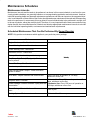
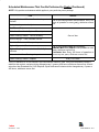
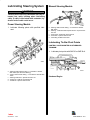
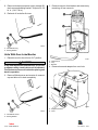
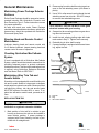
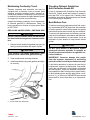
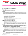
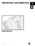
GENERAL INFORMATION
MAINTENANCE
Index
1
B
Table of Contents
Page
Maintenance Schedules . . . . . . . . . . . . . . . . . . . 1B-1
Maintenance Intervals . . . . . . . . . . . . . . . . . . 1B-1
Scheduled Maintenance That Can Be
Performed By Owner/Operator . . . . . . . . . 1B-1
Scheduled Maintenance That Can Be
Performed by Dealer . . . . . . . . . . . . . . . . . . 1B-2
Lubricating Shift Cable Pivot Points . . . . . . 1B-4
Lubricating Propeller Shaft . . . . . . . . . . . . . . . . 1B-4
Lubricating Steering System . . . . . . . . . . . . . . . 1B-5
Power Steering Models . . . . . . . . . . . . . . . . . 1B-5
Manual Steering Models . . . . . . . . . . . . . . . . 1B-5
Lubricating Tie Bar Pivot Points . . . . . . . . . . 1B-5
Control Valve Mounted on Starboard
Transom . . . . . . . . . . . . . . . . . . . . . . . . . . 1B-5
Lubricating Tie Bar Pivot Points . . . . . . . . . . 1B-6
Control Valve Mounted on Port
Transom . . . . . . . . . . . . . . . . . . . . . . . . . . 1B-6
Lubricating Transom Gimbal Housing
Assembly Swivel Shaft, Swivel Pin, Hinge
Pins and Gimbal Bearing . . . . . . . . . . . . . . . . . 1B-6
Checking and Adding Sterndrive Oil . . . . . . . . 1B-7
Units Without Gear Lube Monitor . . . . . . . . 1B-7
Models With Gear Lube Monitor . . . . . . . . . 1B-8
Checking Lubricant for Water . . . . . . . . . . . . . . 1B-8
Models Without Gear Lube Monitor . . . . . . 1B-8
Models With Gear Lube Monitor . . . . . . . . . 1B-9
Page
Changing Sterndrive Oil . . . . . . . . . . . . . . . . . . . 1B-9
Models Without Gear Lube Monitor . . . . . . 1B-9
Units With Gear Lube Monitor . . . . . . . . . . 1B-10
General Maintenance . . . . . . . . . . . . . . . . . . . . 1B-12
Maintaining Power Package Exterior
Surfaces . . . . . . . . . . . . . . . . . . . . . . . . . . . 1B-12
Steering Head and Remote Control
Maintenance . . . . . . . . . . . . . . . . . . . . . . . . 1B-12
Checking Quicksilver MerCathode
System . . . . . . . . . . . . . . . . . . . . . . . . . . . . . 1B-12
Maintaining Alloy Trim Tab and Anodic
Heads . . . . . . . . . . . . . . . . . . . . . . . . . . . . . 1B-12
Replacing Trim Tab . . . . . . . . . . . . . . . . . 1B-12
Maintaining Continuity Circuit . . . . . . . . . . 1B-13
Replacing Anodic Heads - One Each
Side . . . . . . . . . . . . . . . . . . . . . . . . . . . . . 1B-13
Checking Optional Quicksilver
Anti-Corrosion Anode Kit . . . . . . . . . . . . . 1B-13
Boat Bottom Care . . . . . . . . . . . . . . . . . . . . 1B-13
Power Package Layup
(Out of Season Storage) . . . . . . . . . . . . . . . . 1B-14
Engine . . . . . . . . . . . . . . . . . . . . . . . . . . . . . . 1B-14
Sterndrive . . . . . . . . . . . . . . . . . . . . . . . . . . . 1B-14
Power Package Recommissioning . . . . . . . . . 1B-15
Engine . . . . . . . . . . . . . . . . . . . . . . . . . . . . . . 1B-15
Sterndrive . . . . . . . . . . . . . . . . . . . . . . . . . . . 1B-15
Index
1B-0 - MAINTENANCE
90-12934--2 1097
Maintenance Schedules
Maintenance Intervals
Maintenance intervals and the tasks to be performed, as shown in this current schedule, or as found in a previously printed schedules, are generally based on an average boating application and environment. However,
individual operating habits and personal maintenance preferences can have an impact on the suggested intervals. In consideration of these factors, MerCruiser has adjusted some maintenance intervals and corresponding
tasks to be performed. In some cases, this may allow for more individual tasks to be performed in a single visit
to the serving dealer, rather than multiple visits. Therefore, it is very important that the boat owner and servicing
dealer discuss the current Maintenance Schedule and develop appropriate maintenance intervals to coincide
with the individual operating habits, environment and maintenance requirements.
Scheduled Maintenance That Can Be Performed By Owner/Operator
NOTE: Only perform maintenance which applies to your particular power package.
Task
Interval
Engine Crankcase Oil - Check level.
Closed Cooling Coolant - Check level.
Power Steering Fluid - Check level.
Sterndrive Unit Oil - Check level.
Battery - Check level and inspect for damage.
Weekly
Fuel Pump Sight Tube (If Equipped) - Check that no
fuel is present.
Power Trim Pump Oil - Check level.
Anodes - Inspect for erosion.
Gear Housing Water Pickups - Check for marine
growth or debris.
Drive Belts - Inspect condition and check tension.
Every 100 hours of operation or 120 days,
whichever occurs first.
Saltwater Use: Every 50 hours of operation or 60
days whichever occurs first.
first
days,
Power Package - Exterior Surfaces - Spray with rust Freshwater Use: Every 100 hours of operation or
preventative.
120 days, whichever occurs first.
Propeller Shaft - Lubricate.
Power Package Exterior Surfaces - Clean and
paint.
Once a year
Cooling System - Flush seawater section.
Saltwater Use: After every use.
Index
90-12934--2 1097
MAINTENANCE - 1B-1
Scheduled Maintenance That Can Be Performed by Dealer
NOTE: Only perform maintenance which applies to your particular power package.
Task
Seawater Pickup Pump - Disassemble and inspect.
Interval
Whenever insufficient seawater flow is suspected.
(If operating temperature exceeds normal range.)
Crankcase Oil and Filter - Change.
Ignition system - Clean and inspect condition.
Flame Arrestor and Crankcase Ventilation Hose Clean and inspect.
Positive Crankcase Ventilation (PCV) Valve (If
Equipped) - Change.
Sterndrive Unit Oil - Change.
Gimbal Ring Clamping Screws - Retorque to
50-55 ft. lb. (67-74 N·m).
Rear Engine Mounts - Check torque to 30-40 ft. lb.
(47-54 N·m).
Gimbal Bearing - Lubricate.
Cooling System - Clean and inspect.
Steering System - Lubricate and inspect for loose, End of first boating season and thereafter, every 100
hours of operation or once yearly, whichever occurs
damaged or missing parts.
first.
Electrical System - Check for loose or damaged
wiring.
Closed Cooling System Pressure Cap - Clean,
inspect and test .
Cooling System Hoses and Clamps - Inspect for
damage and deterioration. Check clamps for
tightness.
Continuity Circuit - Check components for loose
connections, broken or frayed wires.
Shift and Throttle Cable and Linkage - Lubricate and
inspect for loose, damaged or missing parts.
Engine Exhaust System - Inspect externally for
damage, deterioration and restrictions. Check for
tightness.
Ignition System - Check timing and adjust as needed.
Index
1B-2 - MAINTENANCE
90-12934--2 1097
Scheduled Maintenance That Can Be Performed by Dealer (Continued)
NOTE: Only perform maintenance which applies to your particular power package.
Task
Interval
Steering Head and Remote Control - Inspect and End of first boating season and thereafter, every 100
lubricate.
hours of operation or once yearly,
y
y, whichever occurs
first.
Carburetor - Inspect and adjust.
Fuel Filters - Replace.
Quicksilver Mercathode System - Test output.
Closed Cooling Coolant - Test for alkalinity.
Once a Year
Heat Exchanger - Clean seawater section.
Drive Unit Bellows and Clamps - Inspect.
Engine Alignment - Check.
End of first boating season and thereafter,
S lt t Use:
Saltwater
U
E
Every 300 h
hours off operation
ti or once
Engine Coupling Universal Joint Shaft Splines yearly, whichever occurs first
Lubricate.
Freshwater Use:
Everyy 300 hours of operation or
U
once every two years, whichever occurs first.
Universal Joint Cross Bearings- Inspect.
Closed Cooling Coolant - Replace.
Every Five Years
1Only
if Extended Life 5/100 Ethylene Glycol Antifreeze/Coolant is used. If any non-compatible coolant is
added to this coolant, coolant must be changed every 2 years or 400 hours, whichever occurs first. All coolants other than Extended Life 5/100 Ethylene Glycol Antifreeze/Coolant must be changed every 2 years or
400 hours, whichever occurs first.
Index
90-12934--2 1097
MAINTENANCE - 1B-3
Lubricating Shift Cable Pivot Points
1. Lubricate with SAE 20 or SAE 30 Oil.
50308
Models With Shift Assist Assembly
22911
a - Lubrication Points
Lubricating Propeller Shaft
Early Models
1. Lubricate with Special Lubricant 101, 2-4-C Marine Lubricant With Teflon or Perfect Seal (listed
in order of effectiveness).
22265
Later Models
22074
a - Lubrication Point
Index
1B-4 - MAINTENANCE
90-12934--2 1097
Lubricating Steering System
Manual Steering Models
! WARNING
Transom end of steering cable MUST BE fully retracted into cable housing when lubricating
cable. If cable is lubricated while extended, hydraulic lock of cable could occur.
Power Steering Models
22055
1. Lubricate following points with specified lubricant.
a - Steering Cable Grease Fitting - 2-4-C Marine Lubricant
With Teflon
b - Steering - Cable End And Exposed Portion - Special Lubricant 101
c - Pivot Points - SAE 20 Or 30 Engine Oil
d - Pivot Bolts - Special Lubricant 101
e - Lubricating Tie Bar Pivot Points
Lubricating Tie Bar Pivot Points
CONTROL VALVE MOUNTED ON STARBOARD
TRANSOM
1. Lubricate pivot points with SAE 20 or SAE 30 oil.
22023
a - Steering Cable Grease Fitting - 2-4-C Marine Lubricant
With Teflon (See Previous Warning)
b - Control Valve Grease Fitting - 2-4-C Marine Lubricant With
Teflon
c - Steering Cable End - Special Lubricant 101
d - Pivot Point - SAE 20 Or 30 Engine Oil
e - Pivot Bolts - Special Lubricant 101
22079
Starboard Engine
Index
90-12934--2 1097
MAINTENANCE - 1B-5
Lubricating Transom Gimbal
Housing Assembly Swivel
Shaft, Swivel Pin, Hinge Pins
and Gimbal Bearing
1. Lubricate the following points with specified lubricant.
22079
Port Engine
a - Pivot Points
Lubricating Tie Bar Pivot Points
CONTROL VALVE MOUNTED ON PORT TRANSOM
1. Lubricate pivot points with SAE 20 or SAE 30 oil.
23254
22079
Port Engine
22079
Starboard Engine
a - Pivot Points
23258
a - Swivel Shaft (Later Models May Not Be Equipped With
Fitting) [2-4-C Marine Lubricant With Teflon]
b - Hinge Pin (One Each Side) [2-4-C Marine Lubricant With
Teflon]
c - Gimbal Bearing (U-Joint And Gimbal Bearing Grease)
d - Swivel Pin (2-4-C Marine Lubricant With Teflon)
Index
1B-6 - MAINTENANCE
90-12934--2 1097
Checking and Adding
Sterndrive Oil
6. Without removing lubricant pump from fill/drain
hole, reinstall vent screw and sealing washer.
Torque to 30 - 50 lb. in. (3.4 - 5.7 N·m).
Units Without Gear Lube Monitor
7. Remove lubricant pump and quickly reinstall fill/
drain screw and sealing washer. Torque to 30 - 50
lb. in. (3.4 - 5.7 N·m).
1. Position sterndrive unit so that anti-ventilation
plate is level.
8. Recheck oil level after operation of unit.
2. Remove oil vent plug from drive shaft housing.
3. Check oil level - Oil should be even with bottom
edge of oil vent hole. If oil is at proper level, reinstall vent screw and sealing washer. If oil level is
low, proceed with next steps.
! CAUTION
DO NOT attempt to fill drive unit through oil vent
hole, as air will be trapped in drive unit and unit
will be damaged from lack of lubricant.
23264
a - Oil Vent Screw
b - Sealing Washer
23254
a - Oil Vent Screw
! CAUTION
If more than 2 fl. oz. (60 ml) of oil is required to fill
drive unit, an oil leak may exist. Find and correct
cause of leak before unit is placed in operation.
4. If oil level is low, reinstall oil vent screw and sealing washer. Remove oil fill/drain screw and insert
lubricant pump into oil fill/drain hole.
23266
a - Oil Fill/Drain Screw
b - Sealing Washer
5. Remove oil vent screw. Fill drive unit (through oil
fill/drain hole) with oil until an an air-free stream
of oil flows out of oil vent hole.
Index
90-12934--2 1097
MAINTENANCE - 1B-7
Models With Gear Lube Monitor
IMPORTANT: DO NOT check oil level with drive
unit hot from operation, as hot, expanded oil may
provide a false reading at reservoir. Allow drive
unit to cool prior to checking oil level.
! CAUTION
Checking Lubricant for
Water
Periodically inspect lubricant for water to ensure that
drive unit seals are not leaking.
Models Without Gear Lube Monitor
If color of oil appears milky, or if continuous low
oil level readings in reservoir are noted, a leak
may exist. Find and correct cause for leak before
unit is placed in operation.
1. Trim drive unit to the full trim UP/OUT position.
Remove fill/drain plug to take a sample of lubricant. If water is observed or if lubricant appears
discolored, drive unit is leaking and must be resealed.
1. Maintain oil level to “Full” mark on reservoir. DO
NOT OVERFILL.
2. Reinstall reservoir cap. Make sure cap is tight.
b
70115
a
22101
a - Fill/Drain Plug
b - Sealing Washer Or O-ring
2. Reinstall fill/drain plug. Torque to 30-50 lb. in.
(3.4-5.7 N·m).
22161
a - Oil Reservoir
b - Cap
Index
1B-8 - MAINTENANCE
90-12934--2 1097
Models With Gear Lube Monitor
Changing Sterndrive Oil
Check for water at bottom of monitor. If oil appears
discolored, a water leak is indicated somewhere in
the drive unit and the drive unit must be resealed.
Models Without Gear Lube Monitor
! CAUTION
If more than 2 fl. oz. (59 mL) of Quicksilver Gear
Lube is required to fill monitor, a seal may be
leaking. Find and correct cause of leak before
unit is placed in operation.
! CAUTION
If any water drains from fill/drain hole, or if oil is
discolored, a leak in drive unit may exist. Find
and correct cause of leak before placing unit
back in operation.
IMPORTANT: If drive unit has set overnight or
longer, check for water in drive unit as follows:
! CAUTION
1. Trim drive unit to full UP/OUT position.
DO NOT attempt to fill drive unit thru oil vent hole,
as air will be trapped in drive unit and unit will be
damaged from lack of lubricant.
4. Remove fill/drain screw and vent plug from drive
unit, and allow oil to drain completely.
5. Position drive unit so that anti-ventilation plate is
level.
b
70115
a
22101
a - Oil Fill/Drain Plug
b - Sealing Washer Or O-ring
23253
2. Remove fill/drain plug to sample lubricant. If
water runs out and/or if lubricant appears
discolored, drive unit is leaking and must be
resealed.
3. Reinstall fill/drain plug. Torque to 30-50 lb. in.
(3.4-5.7 N·m).
a - Oil Vent Screw
b - Sealing Washer
6. Using lubricant pump, fill drive unit through fill/
drain hole until oil level is even with bottom edge
of vent hole.
7. Without removing lubricant pump from fill/drain
hole, reinstall oil vent plug and sealing washer.
Torque to 30 - 50 lb. in. (3.4 - 5.7 Nm).
Index
90-12934--2 1097
MAINTENANCE - 1B-9
8. Remove lubricant pump and quickly reinstall fill/
drain screw and sealing washer. Torque to 30 - 50
lb. in. (3.4-5.7 N·m).
3. Remove reservoir from bracket and remove any
remaining oil from reservoir.
9. Recheck oil level after first use.
23266
a - Oil Fill/Drain Plug
b - Sealing Washer
Units With Gear Lube Monitor
1. Raise drive unit to the full trim OUT position.
22161
! CAUTION
If any water drains from fill/drain hole, or if oil color appears milky, a leak in drive unit is indicated.
Find and correct cause of leak before placing unit
back in operation.
a - Oil Reservoir
b - Cap
c - Bracket
4. Remove hose and adapter from vent hole.
2. Remove fill/drain screw and remote oil reservoir
cap and allow oil to drain completely.
23253
23266
a - Adapter and Seal
b - Hose
a - Oil Fill/Drain Screw
b - Sealing Washer
Index
1B-10 - MAINTENANCE
90-12934--2 1097
5. Position sterndrive unit so that anti-ventilation
plate is level.
6. Using lubricant pump, fill drive unit through fill/
drain hole until an air-free stream of oil flows out
of vent hole.
7. Temporarily plug vent hole.
8. Remove lubricant pump and quickly reinstall fill/
drain screw and sealing washer.
9. Unplug vent hole; then, install adapter and sealing washer into vent hole. Torque adapter to
30 - 50 lb. in. (3.4-5.7 N·m). Install reservoir hose
and tighten fitting LOOSELY.
10. Fill oil reservoir to “Fill” mark. DO NOT OVERFILL. Install cap and tighten securely.
11. Loosen hose fitting from adapter until an air-free
stream of oil flows from between adapter and
hose fitting; then, torque hose fitting to 30 - 50 lb.
in. (3.4-5.7 N·m).
12. If necessary, add oil to reservoir up to “Full” mark.
23253
a - Adapter
b - Hose Fitting
23253
a - Vent Hole
23266
b - Fill/Drain Screw
c - Sealing Washer
22161
c - Oil Reservoir
d - Cap
13. Recheck oil level after first use.
Index
90-12934--2 3-194
1097
MAINTENANCE - 1B-11
General Maintenance
Maintaining Power Package Exterior
Surfaces
Entire Power Package should be sprayed at recommended intervals with Quicksilver Corrosion and
Rust Preventive Type II. Follow instructions on can
for proper application.
At least once each year, entire Power Package
should be cleaned and external surfaces, which have
become bare, should be repainted with Quicksilver
Primer and Spray Paint.
Steering Head and Remote Control
Maintenance
Lubricate steering head and remote control with
2-4-C Marine Lubricant. Inspect steering head and
remote control for ease of operation.
2. Remove plug from drive shaft housing to gain access to trim tab attaching screw (not shown in
photo).
3. Use a 3/8 in. alIen wrench and unthread trim tab
attaching screw from trim tab - DO NOT attempt
to remove trim tab attaching screw.
! CAUTION
To be effective, new trim tab MUST make good
electrical contact with gear housing.
4. Scrape trim tab mounting surface on gear housing down to bare metal.
5. Install trim tab, aligning trailing edge with index
mark made in Step 1. Tighten screw securely.
6. Reinstall plug in drive shaft housing.
7. If power package is equipped with manual steering, adjust trim tab.
Checking Quicksilver MerCathode
System
If boat is equipped with a Quicksilver MerCathode
System, system should be tested to ensure that it is
providing adequate output to protect underwater
metal parts on boat. Test should be made where boat
is moored, using Quicksilver Reference Electrode
and Test Meter. Refer to SECTION 7.
Maintaining Alloy Trim Tab and
Anodic Heads
Sterndrive unit is equipped with a sacrificial alloy trim
tab and 2 anodic heads to help protect underwater
metal parts from galvanic corrosion. Because of their
self-sacrificing nature, trim tab and anodic heads
MUST BE replaced if eroded 50% or more. To replace trim tab and/or anodic heads, proceed as follows:
REPLACING TRIM TAB
23253
a - Trim Tab
b - Plug
c - 3/8 in. Allen Wrench
! CAUTION
DO NOT paint new trim tab, as this will render it
ineffective as a galvanic corrosion inhibitor.
1. Mark position of trim tab fin in relation to gear
housing so that new trim tab can be installed in
same relative position. If power package is
equipped with Power Steering, trim tab is positioned with fin straight back.
Index
1B-12 - MAINTENANCE
90-12934--2 1097
Maintaining Continuity Circuit
Transom assembly and sterndrive unit may be
equipped with a continuity circuit to ensure good
electrical continuity between engine, transom assembly and sterndrive components. Good continuity
is essential for the anodes and MerCathode System
(if equipped) to function most effectively.
Inspect the following continuity circuit components,
at intervals specified in “Maintenance Chart,” for
loose connections or broken or fraying wires. Refer
to SECTION 7.
REPLACING ANODIC HEADS - ONE EACH SIDE
! CAUTION
DO NOT paint new anodic heads, as this will render them ineffective as galvanic corrosion inhibitors.
1. Remove anodic heads and gaskets (not seen) by
turning counterclockwise with a pair of pliers.
! CAUTION
To be effective, new anodic heads MUST make
good electrical contact with gimbal housing.
2. Clean anodic head mounting surfaces.
3. Install new heads (using new gaskets) and tighten securely.
Checking Optional Quicksilver
Anti-Corrosion Anode Kit
If boat is equipped with Quicksilver Anti-Corrosion
Anode Kit, inspect anode and replace if eroded to
less than 50% of its original size. Carefully follow
installation instructions that accompany new Anode
Kit to ensure proper installation.
Boat Bottom Care
To achieve maximum performance and fuel economy, boat bottom MUST BE kept clean. Accumulation
of marine growth or other foreign matter can greatly
reduce boat speed and increase fuel consumption.
To ensure best performance and efficiency, periodically clean boat bottom in accordance with manufacturer’s recommendations. In some areas, it may be
advisable to paint bottom to help prevent marine
growth.
! CAUTION
DO NOT paint anodes or MerCathode System
anode and reference electrode, if equipped, as
this will render them ineffective as a gaIvanic corrosion inhibitors.
IMPORTANT: Corrosion damage that results
from the improper application of anti-fouling
paint will not be covered by the limited warranty.
If anti-fouling protection is required for boat hull or
boat transom, copper or tin base paints, if not prohibited by law, can be used. If using copper or tin based
anti-fouling paint, avoid any electrical interconnection between the MerCruiser product, anodic blocks,
or MerCathode system and the paint. Allow a minimum of 11/2 in. (40 mm) of UNPAINTED area around
these items to ensure that there is no interconnection.
22090
a - Anodic Heads (One Each Side)
Index
90-12934--2 1097
MAINTENANCE - 1B-13
Power Package Layup
(Out of Season Storage)
Engine
Refer to appropriate Engine Service Manual.
Sterndrive
1. Lubricate steering system. Refer to SECTION
1-B.
2. Lubricate transom gimbal housing assembly
swivel shaft and pin, hinge pins, gimbal bearing
and propeller shaft. Refer to SECTION 1-B.
71176
Paint the drive unit and transom assembly with a
good quality marine paint or anti-fouling paint that
DOES NOT contain copper, tin, or any other material
that could conduct electrical current. Do not paint
drain holes, anodes, MerCathode system, or items
specified by the boat manufacturer.
Spray power package components inside the boat
every 2 - 3 weeks with Quicksilver Corrosion Guard
to protect the finish from dulling and corrosion. External power package components may also be
sprayed.
All lubrication points, especially steering system,
shift and throttle linkages should be kept well lubricated. Flush the cooling system periodically, preferably after each use.
3. Lubricate sterndrive unit U-Joint shaft splines
and cross bearings. Refer to SECTION 3-A.
4. Inspect U-Joint bellows for cracks or other signs
of deterioration. Check bellows clamps for tightness. Refer to SECTION 4.
5. Check engine alignment. Refer to Engine
Service Manual.
6. Change sterndrive unit oil.
! CAUTION
Water drain holes in sterndrive unit MUST BE
open to allow water to drain, or trapped water
may freeze and cause severe damage to
housings.
Index
1B-14 - MAINTENANCE
90-12934--2 1097
7. Using a piece of wire, check water drain holes in
sterndrive unit to ensure that they are open.
11. If not already done, place sterndrive unit in the full
trim IN/DOWN position.
12. Store battery, using the following procedure.
a. Remove battery as soon as possible and remove all grease sulfate and dirt from top surface.
b. Fill battery with distilled water to level specified by manufacturer.
c. Cover terminal bolts well with petroleum base
grease.
d. Store battery in a COOL, DRY place in a dry
carton or box.
! CAUTION
A discharged battery can be damaged by freezing.
e. Remove battery from storage every 45 days.
Check water level and place on charge, following battery manufacturer’s instructions.
DO NOT fast charge.
23253
Sterndrive Unit Water Drain Holes
a - Drive Shaft Housing Water Drain Holes (Two Each Side)
b - Gear Housing Water Drain Hole
8. Inspect sterndrive for damage. Repair or replace
damaged components.
9. Clean sterndrive exterior surfaces and repaint
any bare metal surfaces with Quicksilver Primer
and Spray Paint. Refer to SECTION 1-B.
10. After paint has dried spray entire sterndrive with
Quicksilver Corrosion Guard. Refer to SECTION
1-B.
NOTE: Larger batteries generally will accept a higher
charging rate.
f.
When replacing battery in service, remove
excess grease from terminals (leaving small
amount on), recharge as necessary and reinstall in your equipment.
Power Package
Recommissioning
Engine
Refer to appropriate Engine Service Manual.
! CAUTION
The gear case exhaust cavity might fill with water
and freeze if stored in the UP/OUT position. Avoid
gear case damage by storing the sterndrive unit
in the full IN/DOWN position.
! CAUTION
U-Joint bellows may develop a “set” if unit is
stored in raised position and may fail when unit
is returned to service. Store sterndrive unit in the
full trim IN/DOWN position.
Sterndrive
1. Perform ALL maintenance specified for completion “At Least Once Each Year” in “Maintenance
Chart” (In Front of This Section), except items
which were performed at the time of sterndrive
Iay up.
2. Install fully-charged battery. Clean battery cable
clamps and terminals and reconnect cables. Be
sure to tighten clamps securely. Apply a thin coat
of petroleum base grease to clamps and terminals to help retard corrosion.
3. After recommissioning and starting engine,
check steering system and shift control for proper
operation.
Index
90-12934--2 1097
MAINTENANCE - 1B-15
THIS PAGE IS INTENTIONALLY BLANK
Index
1B-16 - MAINTENANCE
90-12934--2 1097