1
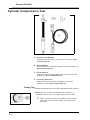
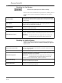
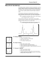
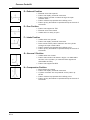
Pressure Probes
EAK0171L00A (100 psi), EAK0171L10A (500 psi), EAK0171L20A (5000 psi)
Table of Contents
Safety Information . . . . . . . . . . . . . . . . . . . . . . . . . . . . . . . . . . . . . . . . . . . . . . . . . . . . . . . . . . . . . 1
Introduction . . . . . . . . . . . . . . . . . . . . . . . . . . . . . . . . . . . . . . . . . . . . . . . . . . . . . . . . . . . . . . . . . . 4
Functional Description . . . . . . . . . . . . . . . . . . . . . . . . . . . . . . . . . . . . . . . . . . . . . . . . . . . . . . . . . . 4
Connections . . . . . . . . . . . . . . . . . . . . . . . . . . . . . . . . . . . . . . . . . . . . . . . . . . . . . . . . . . . . . . 5
Test Preparations . . . . . . . . . . . . . . . . . . . . . . . . . . . . . . . . . . . . . . . . . . . . . . . . . . . . . . . . . . . . . 6
Pressure Probe Tests . . . . . . . . . . . . . . . . . . . . . . . . . . . . . . . . . . . . . . . . . . . . . . . . . . . . . . . . . . 6
Before Testing . . . . . . . . . . . . . . . . . . . . . . . . . . . . . . . . . . . . . . . . . . . . . . . . . . . . . . . . . . . . . 7
Cylinder Compression Test . . . . . . . . . . . . . . . . . . . . . . . . . . . . . . . . . . . . . . . . . . . . . . . . . . . 8
Waveform Guidelines . . . . . . . . . . . . . . . . . . . . . . . . . . . . . . . . . . . . . . . . . . . . . . . . . . . . . . 11
Additional Cylinder Pressure Tests . . . . . . . . . . . . . . . . . . . . . . . . . . . . . . . . . . . . . . . . . . . . 13
Engine Oil Pressure Test . . . . . . . . . . . . . . . . . . . . . . . . . . . . . . . . . . . . . . . . . . . . . . . . . . . 16
Transmission Pressure Test . . . . . . . . . . . . . . . . . . . . . . . . . . . . . . . . . . . . . . . . . . . . . . . . . 18
Safety Information
IMPORTANT SAFETY INSTRUCTIONS
Pressure probes are highly sophisticated test instruments
intended for use by properly trained, skilled professional
automotive technicians. Safety warnings and cautions in this
manual are reminders to operator to exercise extreme care when
using this test instrument.
There are many variations in procedures, techniques, tools, and
parts for servicing vehicles, as well as in the skill of the individual
doing the work. Because of the vast number of test applications
and variations in the products that can be tested with this
instrument, Snap-on cannot possibly anticipate or provide advice
or safety messages to cover every situation. It is the automotive
technician’s responsibility to be knowledgeable of the system
being tested. It is essential to use proper service methods and test
procedures and to perform tests in an appropriate and acceptable
manner that does not endanger your safety, safety of others in the
work area, or vehicle or equipment being tested.
It is assumed the operator has a thorough understanding of vehicle
systems before using the pressure probes. Understanding of these
systems principles and operating theories is necessary for
competent, safe and accurate use of this instrument.
Use equipment only as described in this manual.
PP-1
Pressure Probe Kit
Read All Instructions
Read, understand and follow all safety messages and instructions
in this manual and on the test equipment. Safety messages in this
manual contain a signal word with a three-part message and, in
some instances, an icon.
The signal word indicates level of hazards in a situation.
• DANGER indicates an imminently hazardous situation
which, if not avoided, will result in death or serious injury to
operator or bystanders.
• WARNING indicates a potentially hazardous situation which,
if not avoided, could result in death or serious injury to
operator or bystanders.
• CAUTION indicates a potentially hazardous situation which,
if not avoided, may result in moderate or minor injury to
operator or bystanders.
Safety messages in this manual contain three different type styles
• Normal type states the hazard.
• Bold type states how to avoid the hazard.
• Italic type states the possible consequences of not avoiding
the hazard.
An icon, when present, gives a graphical description of the
potential hazard.
SAVE THESE INSTRUCTIONS
Risk of explosion.
• Exceeding the pressure limits of the pressure
probes and/or adaptors can cause the equipment
to burst.
• The pressure probe lead used with pressure
probes should not be exposed to temperatures
exceeding 250 °F.
Explosion can cause injury.
Risk of sudden vehicle movement.
• Set the gear selector in neutral for a standard
transmission or park for an automatic
transmission. Set the parking brake. If the vehicle
has an automatic parking brake release,
disconnect the release mechanism for testing and
reconnect when testing is completed.
• Disable fuel and ignition systems before testing.
Check manufacturer’s service manual for
procedures.
A moving vehicle can cause injury.
PP-2
Pressure Probe Kit
Risk of flying particles.
• Wear safety goggles, user and bystander.
• Do not exceed specified operating psi for any
pressure probe.
• Be sure all connections are secure.
Flying particles can cause eye injury.
Risk of entanglement.
Keep yourself, clothing and test equipment clear of
moving parts.
Entanglement in moving parts can cause injury.
Be sure that all of the equipment that is being used is
approved for the use intended and can handle the
pressure involved in the testing sequence. Use only as
described in this instruction manual. Use only the
manufacturers recommended attachments.
Risk of burns.
Do not expose the pressure probe lead used with
pressure probes to temperatures exceeding 250 °F.
Burns can cause injury.
• Before each use of this accessory, inspect the
connector for bent or missing pins, and inspect the
cable for damage. Also, inspect both connectors
for foreign objects or dirt, and clean if necessary.
• When inserting the connectors, align the keyed
detents. Do not use excessive force, and do not
rock the connectors back and forth while inserting.
• When removing the connectors, grasp the
connector housing. Do not pull the cable.
• Do not let the cable touch the exhaust manifold.
• Flush pressure transducer, hoses and adaptors
with gasoline or parts cleaning solvent after use
with methanol or methanol blended gasolines.
• Periodically check all parts of the pressure probe
kit for signs of wear or damage, and replace items
when worn. Never use equipment that is showing
signs of wear or damage, until it has been
examined by a qualified Snap-on service
representative.
• Pressure transducers, hoses and adaptors should
always be flushed with a solvent after any use to
prevent the cross contamination of various fluids
and systems. (air conditioning, power steering,
transmission fluid, brake fluid, fuel, coolant).
PP-3
Pressure Probe Kit
Introduction
Use the Sun pressure probe kits with the Pressure Probe Scope
feature to test any vehicle system requiring pressure
measurements and to view the pressure measurements over time.
There are three Sun pressure probe kits which can be used with
any Sun Machine or Counselor II tester.
Each kit contains one pressure probe.
• 100 psi Pressure Probe Kit, part number EAK0171L100A
— The 100 psi kit includes harness EAX0033L00A
• 500 psi Pressure Probe Kit, part number EAK0171L10A
• 5000 psi Pressure Probe Kit, part number EAK0171L20A
Functional Description
Figure 1: Pressure Probe and Harness
A – Pressure Probes
100 psi, part number 2-16366
500 psi, part number 2-16466
5000 psi, part number 2-16566
B – Pressure Probe Lead
Part number EAX0033L00A. Connects from the auxiliary extension
lead (not shown) to the pressure probe (A).
✓
PP-4
Included with the 100 psi Pressure Probe Kit only. The
pressure probe lead kit may be ordered separately as
part number EAK0171L30A for use with the 500 psi
and the 5000 psi Pressure Probe Kits.
Pressure Probe Kit
Pressure Probe Kit
100 psi
EAK0171L100A
System
Possible Tests
Fuel
– Fuel Injector Drop Tests
– Fuel pumps
Oil
– Sticking pressure relief valves
– Anti-Drainback valve
Internal Engine
–
–
–
–
–
–
–
–
–
–
Valve train
Compression
Fuel system
Oil system
Exhaust restrictions
Piston ring integrity
Intake integrity
Head gaskets failure
Open gasket failure
Camshaft timing failure
–
–
–
–
–
–
–
Restricted filters
Clutch and band
Internal
Solenoid pack
Electronic failure
Line pressure
Worn seals
500 psi
EAK0171L10A
Transmission/Transaxle
Power Steering
5000 psi
EAK0171L20A
Brakes
– Pump and rack
– Variable assist
– ABS
The following sections contain typical examples of some of these
tests.
• Set the gear selector in neutral for a standard
transmission or park for an automatic
transmission. Set the parking brake. If the vehicle
has an automatic parking brake release,
disconnect the release mechanism for testing and
reconnect when testing is complete
• Read, understand and follow Safety Information in
the front of this manual.
Connections
Use this procedure to connect the pressure probe to the tester and
vehicle for all tests in this section.
1. Connect auxiliary extension lead to the TIMING/AUX
receptacle on the connection panel.
2. Connect pressure probe lead to the auxiliary extension
lead.
PP-5
Pressure Probe Kit
3. Connect pressure probe to the pressure probe lead.
4. Calibrate the pressure probe.
✓
For additional information refer to Pressure Probe
Calibration.
5. Connect pressure probe to vehicle.
6. Select Scope
— Special Patterns
— Pressure Probes
7. Setup Scope as necessary for testing.
✓
Pressure probe calibration is required when a different
pressure probe is selected or if exit and return to the
scope. Calibrate pressure probes at any time by
selecting Pressure Probe Calibration from Tools (F4).
Test Preparations
Tests in this manual assume that:
• Tester is on, warmed up and calibrated,
• Leads are connected to vehicle in standard configuration,
• Vehicle identified using Vehicle ID:
— Description,
— Quick ID, or
— Restore Data.
• Vehicle parking brake is applied.
• Gear selector is in:
— Neutral, if equipped with a manual transmission, or
— Park, if equipped with an automatic transmission.
• Drive wheels are blocked,
• Parking brake is set, and
— If vehicle equipped with automatic parking brake release,
disable release mechanism.
• All testing tips and safety requirements are observed.
Pressure Probe Tests
Use any of the 0-100, 0-500, and 0-5000 psi pressure probes on
any vehicle system requiring pressure measurements.
Pressure probes must be calibrated before each use to
maintain accuracy.
✓
PP-6
For additional information refer to Pressure Probe
Calibration in this manual.
Pressure Probe Kit
Before Testing
Perform pressure probe calibration before testing.
✓
Refer to Safety Information in the front of this manual
and testing tips included with each test.
Pressure Probe Calibration
Pressure probe must be calibrated before each use to maintain
accuracy.
To perform pressure probe calibration select:
— F10 to calibrate the pressure probe connected to
the tester.
— F9 to use the last good calibration if the pressure
probe was recently calibrated and conditions have
not changed.
✓
✓
The scope stores calibration data from the last
pressure probe calibrated until you exit the scope or a
different pressure probe is selected and calibrated.
Select F4 to recalibrate the pressure probe at any
time. Select Calibrate Pressure Probe from the Tools
menu. To maintain accuracy, recalibrate the pressure
probe if subjected to temperature changes during
testing.
If a pressure probe fails to calibrate, check all probe and cable
connections.
PP-7
Pressure Probe Kit
Cylinder Compression Test
Figure 2: Optional Accessories
A – Cylinder Test Adaptor
Connects from the quick coupler (C) to the vehicle. Not
included with kit.
B – Brass Adaptor
Connects from the pressure probe to the quick coupler (C).
Not included with kit.
C – Quick Coupler
Connects from the brass adaptor (B) to the cylinder test
adaptor (A). Not included with kit.
D – Auxiliary Extension
Adapts the timing auxiliary receptacle for use with
pressure probes. Not included with kit.
Testing Tips
r Starter should be able to maintain adequate cranking speed.
r Make sure the cylinder test adaptor does not have a
Schrader valve in the end or test results will be invalid.
✓
PP-8
When using the cylinder test adaptor, the Schrader
valve must be removed to obtain a valid pressure
waveform.
Pressure Probe Kit
Test
1. Select Setup to set the following scope functions for
standard testing:
— Signal, Channel 1 - Aux 500 psi
— Channel 2, Off
— Pattern/Sweep,
— 1 sec or 500ms depending on viewing preference
and cranking speed of engine
— Scale, 250 psi
— Trigger, Auto
2. Run vehicle engine to achieve normal operating
temperature.
• Do not touch hot engine components.
• Wear gloves when handling hot engine
components.
The engine must be at normal operating temperature.
A cold engine will give low and inconsistent readings.
Complete this test before the engine cools.
3. Disable vehicle ignition system.
✓
For additional information refer to Disabling the
Ignition System at the end of this section .
4. Remove vehicle air cleaner.
5. Disable vehicle fuel system.
✓
For additional information refer to Disabling the Fuel
System at the end of this section.
6. Remove spark plug.
7. Attach cylinder pressure test adaptor to engine.
8. Attach pressure probe to cylinder pressure test
adaptor.
9. Open engine throttle.
10. Crank engine through at least 6 compression cycles.
✓
✓
Refer to vehicle manufacturer specifications for
compression data.
For waveform interpretation information refer to
Waveform Guidelines on page PP-11.
PP-9
Pressure Probe Kit
Disabling the Fuel System
Relieve fuel system pressure before testing.
Refer to the vehicle manufacturer’s procedure for disabling the fuel
system. Some common methods of disabling the fuel system
follow.
Clear Flood Mode
– Many newer fuel injected systems can be put into this mode by depressing the
accelerator fully to the floor and cranking the engine. This keeps the fuel injectors
from activating.
Inertia Switch
– Most Ford vehicles are equipped with an inertia switch. Lifting the plunger on the
top of the switch deactivates the fuel pump. After "tripping" the switch, crank the
engine to burn any residual fuel in the fuel rail.
Fuel Pump Relay
– May be centrally located in the power distribution or maxi-fuse panels, remove
this relay to disable the fuel pump.
Fuel Injector Fuse(s)
– Usually located in the fuse panel, removing this fuse disables the fuel injectors.
ECM/PCM Power Fuse(s)
– Usually located in the fuse panel, removing this fuse can disable the fuel
injectors. Sometimes it disables the fuel and ignition systems. Be sure to check
for spark.
IMPORTANT: Be aware these fuses may supply "keep alive" memory and
removing them may erase learned memory from the PCM.
Disabling the Ignition System
Refer to the vehicle manufacturer’s procedure for disabling the
ignition system. Some common methods of disabling the ignition
system follow.
External Coils and Coil Wire
– Disconnect primary wiring connector from ignition coil.
– Remove coil secondary wire from distributor cap and with a jumper wire connect
it to a known good ground.
Internal Coils
– Disconnect primary wiring connector from the distributor or from igniter module.
Distrubutorless Ignition
– ECM/PCM Power Fuse(s) - Usually located in the fuse panel, these fuses can be
removed and the ignition may be disabled.
IMPORTANT: Be aware these fuses may supply "keep alive" memory and
removing them may erase learned memory from the PCM.
– Remove connector at ignition module, igniters or coilpack(s).
Ignition Control Relay
– Usually located in the power distribution or maxi-fuse panel, this relay can be
removed to disable the ignition system.
Ignition Control Fuse
– Usually located in the power distribution or maxi-fuse panel, this fuse can be
removed to disable the ignition system.
PP-10
Pressure Probe Kit
Waveform Guidelines
The cylinder pressure waveform charts the compression cycle of a
cylinder. Refer to the normal cylinder pressure waveform, Figure 3
with open throttle. Although minor variances occur depending on
the design of the engine being tested, the general characteristics
of the "normal" cylinder pressure waveform always remains the
same.
A low pressure reading at the ready position of the cylinder
pressure waveform indicates either a camshaft timing failure or an
engine mechanical failure of piston rings, valves, head gasket.
✓
For additional information refer to Piston Ring Integrity
Test to diagnose piston ring failure.
A high pressure reading at the ready position of the cylinder
pressure waveform indicates either a camshaft timing failure or an
excessive carbon build-up on the cylinder head.
✓
For additional information refer to Camshaft Timing
Failure to diagnose a camshaft timing problem.
Figure 3 : Normal Cylinder Pressure Waveform
A—Ready Position
—
—
—
—
Piston has stopped at TDC
Cylinder contents are compressed
Both valves are closed
All is ready for spark ignition
B—Power Position
—
—
—
—
Both valves remain closed
Piston has rapidly resumed movement
Piston reaches top speed at the halfway point
Piston quickly decreases in speed and stop at the end of
the stroke
C—Vacuum 1 Position
— Piston has stopped at BDC
— Both valves remain closed
— Cylinder pressure has dissipated, and the rapid downstroke of the piston has drawn a vacuum in the cylinder
— Exhaust valve is ready to open
PP-11
Pressure Probe Kit
D—Exhaust Position
— Exhaust valve has opened
— Piston has rapidly resumed movement
— Piston expels cylinder contents through the open
exhaust valve
— Piston reaches top speed at the halfway point
— Piston quickly decreases in speed and stop at the end of
the stroke
E—Zero Position
— Piston has stopped at TDC
— Exhaust valve has closed
— Intake valve is ready to open
F—Intake Position
— Intake valve has opened
— Piston has rapidly resumed movement
— Down-stroke of the piston draws air into the cylinder
through the open intake valve
— Piston reaches top speed at the halfway point
— Piston quickly decreases in speed and stop at the end of
the stroke
G—Vacuum 2 Position
— Intake valve has closed
— Piston down-stroke has drawn a slight, non-detectable
vacuum in the cylinder. (A closed throttle registers a
detectable vacuum.)
— Piston has stopped at BDC
H—Compression Position
— Both valves are closed
— Piston has rapidly resumed movement
— Cylinder contents are compressed on the piston upstroke
— Piston reaches top speed at the halfway point
— Piston quickly decreases in speed and stop at the end of
the stroke
PP-12
Pressure Probe Kit
Additional Cylinder Pressure Tests
•
•
•
•
•
•
•
Piston Ring Integrity Test
Intake Integrity Test
Exhaust Restriction
Intake Restriction
Head Gasket Failure
Open Valve Failure
Camshaft Timing Failure
Piston Ring Integrity Test
✓
For waveform interpretation information refer to
Waveform Guidelines on page PP-11.
1. Perform Cylinder Compression Test.
2. Save results.
3. Remove pressure probe from cylinder pressure test
adaptor.
4. Remove cylinder pressure test adaptor from engine.
5. Squirt a small quantity of oil in open cylinder to seal
any existing cylinder wall clearance.
6. Perform Cylinder Compression Test again.
7. Save results.
8. Compare results of the initial test with the results of the
second test.
Interpretation
• No significant change in the ready position of the cylinder
pressure waveform indicates piston ring integrity.
• A significant increase in the ready position of the cylinder
pressure waveform indicates piston ring leakage.
Intake Integrity Test
✓
For waveform interpretation information refer to
Waveform Guidelines on page PP-11.
1. Perform Cylinder Compression Test.
2. Save results.
3. Close engine throttle or manually block throttle body
opening.
4. Perform Cylinder Compression Test with closed
throttle.
5. Compare results.
PP-13
Pressure Probe Kit
Interpretation
• Significant change in the intake position of the cylinder
pressure waveform indicates intake integrity.
• No significant change in the intake position of the cylinder
pressure waveform indicates intake leakage.
Figure 4: Intake Integrity Test
Exhaust Restriction
An exhaust restriction can be detected on the cylinder pressure
waveform.
✓
For waveform interpretation information refer to
Waveform Guidelines on page PP-11.
Interpretation
• An unrestricted exhaust registers no significant pressure
during the exhaust position of the cylinder pressure
waveform. A restricted exhaust registers significantly higher
pressure.
• To diagnose the point of restriction, test adjacent cylinders
and/or opposite cylinder bank.
Figure 5: Exhaust Restriction Waveform
Intake Restriction
Performing a cylinder pressure test can detect an intake
restriction.
✓
For waveform interpretation information refer to
Waveform Guidelines on page PP-11.
Interpretation
• An unrestricted intake registers no significant vacuum in a
"throttle-open" mode during the intake position of the
cylinder pressure waveform.
• A restricted intake draws a detectable vacuum in a "throttleopen" mode during the intake position of the cylinder
pressure waveform.
• To diagnose the point of restriction, test adjacent cylinders
and/or opposite cylinder bank.
PP-14
Pressure Probe Kit
Head Gasket Failure
To detect head gasket failure on the cylinder pressure waveform,
first verify piston ring integrity.
✓
✓
For additional information refer to Piston Ring Integrity
Test.
For waveform interpretation information refer to
Waveform Guidelines on page PP-11.
Interpretation
• A failed head gasket is indicated by a loss of pressure
during the Compression Position and Vacuum Positions 1
and 2 of the cylinder pressure waveform.
• To verify a failed head gasket indication, test adjacent
cylinders for similar results.
Figure 6 : Head Gasket Failure
Open Valve Failure
✓
For waveform interpretation information refer to
Waveform Guidelines on page PP-11.
1. To detect open valve failure on the cylinder pressure
waveform, first verify piston ring integrity.
✓
For additional information refer to Piston Ring Integrity
Test.
2. After piston ring integrity has been verified and the
possibility of a head gasket failure has been
eliminated, perform Cylinder Compression Test with
closed throttle.
Interpretation
Open valve failure is indicated by a loss of pressure during the
Compression Position and Vacuum Positions 1 and 2 of the
cylinder pressure waveform.
PP-15
Pressure Probe Kit
Camshaft Timing Failure
✓
For waveform interpretation information refer to
Waveform Guidelines on page PP-11.
Timing failure can be detected on the cylinder pressure waveform.
Timing failure is indicated by either:
• A lower than normal pressure reading at the ready position
of the cylinder waveform with higher than normal readings at
Vacuum Positions 1 and 2 of the cylinder waveform, or
• A higher than normal pressure reading at the ready position
of the cylinder waveform with lower than normal readings at
Vacuum Positions 1 and 2 of the cylinder waveform.
To verify camshaft timing failure, test non-adjacent cylinders or
opposite bank cylinders for similar results.
Engine Oil Pressure Test
The oil pressure waveform shows internal oil pressure fluctuations
over a specific period of time and conditions.
Figure 7: Normal Oil Pressure
Testing Tips
r At normal operating temperature, the rise to full stable oil
pressure typically takes less than one second. When oil
pressure testing is performed on a cold engine, it typically
takes longer to register full stable oil pressure.
r A cold engine typically has higher than normal oil pressure
until the engine reaches normal operating temperature.
r Oil pressure typically increases with higher engine RPM and
decreases with lower engine RPM.
r Over an extended period of running time at constant RPM,
engine oil pressure normally drops. Engine oil becomes
thinner as the engine temperature increases and allows oil
to flow more easily past the engine bearings.
Test
1. For
—
—
—
—
—
PP-16
standard testing:
Set Signal: Channel 1 - Aux 500 psi
Channel 2 - OFF
Set Pattern/Sweep: 10 sec
Set Scale: 100 psi
Set Trigger: Auto
Pressure Probe Kit
2. Locate and remove engine oil pressure sending switch.
Do not touch hot engine components.
Wear gloves when handling hot engine components.
3. Attach oil pressure test adaptor to oil pressure sending
switch port on engine.
4. Attach pressure probe to oil pressure test adaptor.
When installing the pressure probe into the appropriate
adaptor, use care to not overtighten the pressure
probe.
5. Start engine.
6. Run vehicle engine to achieve normal operating
temperature.
Internal Pressure-Relief Valve Failure (Sticking)
The oil pressure waveform rises quickly to point (A). Typically, the
oil pressure waveform then drops to point (B) and levels out at
point (C).
Figure 8: Internal Pressure Relief Valve Failure
Filter Anti-Drainback Valve Failure
The engine must be at ambient temperature to accurately identify
this condition.
The oil pressure waveform rises relatively slowly under this
condition. The oil pressure waveform will typically "plateau"
midway and slowly level off at normal pressure.
Figure 9: Filter Anti-Drainback Valve Failure
PP-17
Pressure Probe Kit
Transmission Pressure Test
The automatic transmission/transaxle pressure waveform charts
internal automatic transmission/transaxle pressure fluctuations
over a specific period of time and conditions. A "normal" automatic
transmission/transaxle pressure waveform under high line
pressure (low gear / 'D1' or reverse / 'R') is shown below. Although
minor variances occur depending on the design of the automatic
transmission/transaxle being tested, the general characteristics of
the "normal" automatic transmission/transaxle pressure waveform
always remains the same.
✓
Pump activity may create harmonics, or jagged line, at
full pressure.
Figure 10: Normal Automatic Transmission/Transaxle Waveform - High Pressure
Testing Tips
r Under normal operating conditions, the rise to full stable
automatic transmission/transaxle pressure typically takes
less then one second. When automatic transmission/
transaxle pressure testing is performed on a cold automatic
transmission/transaxle, it typically takes slightly longer to
register full stable automatic transmission/transaxle
pressure.
r A cold automatic transmission/transaxle typically has
slightly higher than normal pressure until the automatic
transmission/transaxle reaches normal operating
temperature.
Test
1. For
—
—
—
—
standard testing:
Set Signal Aux: Off / 500 psi
Set Pattern/Sweep: 5 sec
Set Scale: 250 psi
Set Trigger: Auto
2. Locate automatic transmission/transaxle test ports per
manufacturer specifications.
3. Attach automatic transmission/transaxle pressure test
adaptor to the desired automatic transmission/
transaxle test port.
Exceeding the pressure limits of the pressure probes
and/or adaptors can cause the equipment to burst.
PP-18
Pressure Probe Kit
4. Attach pressure probe to automatic transmission/
transaxle pressure test adaptor. When installing the
pressure probe into the appropriate adaptor, do not
overtighten the pressure probe.
5. Using appropriate safety equipment, lift vehicle to
disengage drive wheels from ground or
6. Apply vehicle parking brake and block appropriate drive
wheels according to gear selected for test.
Set the gear selector in neutral for a standard
transmission or park for an automatic transmission.
Set the parking brake. If the vehicle has an automatic
parking brake release, disconnect the release
mechanism for testing and reconnect when testing is
completed.
Disable fuel and ignition systems before testing.
Check manufacturer’s service manual for procedures.
7. Start engine.
8. Select appropriate gear.
Interpretation Examples
Normal Automatic Transmission/Transaxle - Low Pressure
A typical normal automatic transmission/transaxle waveform under
low pressure (all gears except low gear / 'D1' and reverse / 'R') is
shown below.
Figure 11: Normal Transmission/Transaxle Waveform - Low Pressure
Electronic Failure or Ball Seat Failure
Under these conditions, the automatic transmission/transaxle
pressure waveform typically registers sharp increases with a
'plateau' or 'stair-step' pattern.
Figure 12: Ball Seat Failure
PP-19
Pressure Probe Kit
Worn Clutch Seal or Worn Band Servo Seal / Restricted Filter
The transmission/transaxle must be at or below ambient
temperature to accurately identify this condition.
At ambient temperature or below (hyphenated line), the automatic
transmission/transaxle pressure waveform rises slowly under both
conditions.
— Worn Seal - When the automatic transmission/transaxle
reaches normal operating temperature, the seals
typically function normally and the automatic
transmission/transaxle waveform appears normal (wide
line).
Figure 13: Worn Seat
— Restricted Filter - When the transmission/transaxle
reaches normal operating temperature, the automatic
transmission/transaxle pressure waveform appears
similar to the ambient temperature waveform, with a
slight variance due to the altered viscosity of the fluid.
(thin line).
Figure 14: Restricted Filter
8-3563
©2000 Snap-on Tools Company
Printed in U.S.A. (2/00)