1
AFTER UNPACKING
It is advisable to save all original packing cartons (inner and
outer) to protect your valuable transceiver from damage
should you wish to transport i t for remote operation or ship it
for after-sales service.
The following explicit definitions apply i n this manual. Be
sure to read these definitions:
NOTE:
CAUTION:
If disregarded. inconvenience only - no
damage or personal injury.
Equipment damage may occur, but not
personal injury.
WARNING:
Personal injury may occur
d~sregard.
- do not
CAUTION:
Read Operating Manual Section 4. before placing
transmitter in service.
WARNING: HIGH VOLTAGES PRESENT.
CONTENTS
SPECIFICATIONS ................................................. 3
SECTION 1. INTRODUCTION A N D FEATURES .... 4
SECTION 2. INSTALLATION .................................. 5
2.1. Unpacking
2.2 Operating Location
2.3 Cabling
2 . 4 Microphone
2.5 Key
2.6 External Speaker and Headphones
2.7 Ground
2.8 Antenna
SECTION 3. CONTROLS A N D THEIR FUNCTIONS 8
3.1 Front Panel
3.2 Rear Panel
SECTION 4. OPERATION ....................... ....
. 14
4.1 Reception (I)
(1) Basic Procedures for Receive Operation
(2) WWV Reception
4.2 Reception (11)
(1) RF ATT Switch
(2) RF Gain Control
(3) AGC (Automatic Gain Control)
(4) RIT/XIT
(5) IF Shift
(6) NARROW Switch
(7) Noise Blanker (NB)
4.3
4.4
4.5
4.6
SECTION
5.1
5.2
SECTION
6.1
6.2
6.3
6.4
6.5
6.6
Transmission (I)
(1) SSB Operation
Transmission (11)
( 1 ) Speech Processor
(2) VOX (Voice Operated Transmit) Operation
(3) XIT (Transmitter Incremental Tuning)
( 4 ) CW Operation
Digital Display Calibration
Analog Dial Calibration
5. OPTIONAL ACCESSORIES ................ 22
Optional Accessories
Installation of Accessories
6. MAINTENANCE A N D ALIGNMENT .. 26
General
Service Position
Receiver Adjustments
Transmitter Adiustments
Transmitting on WARC BANDS
Operation on 220V AC or 240V AC (USA)
SECTION 7. TROUBLESHOOTING ......................... 2 8
BLOCK D I A G R A M................................................... 2 9
INTERNAL VIEW ..................................................... 3 0
SCHEMATIC DIAGRAM ............
31
................
.
.
.
.
a,.;
.........
SECTION 2.
INSTALLATION
.............................................................
lll..~,,,,..~,~~,...ll,,...,,,*...,,,#...,,,,...,,,,,.~,,,,..,,,l~,..llll,..,,,,,..,,,,,.,,,,,..,,,,,...",,#.,
2.1 UNPACKING
Remove the TS-530s from its shipping container and
packing material and examine it for visible damage. If the
equipment has been damaged in shipment, notify the
transportation company immediately. Save the boxes and
packing material for future shipping or moving.
#,,,l...tl1,...11,l..~,lll...IIII1..,*,,...,,,,...",,...,,,,..~*ll,~.~llll*.~lllt~..llIt...llll...lll~...ll~
W POWER CONNECTIONS
Make sure the POWER switch on the front panel is turned
off, the stand-by switch is in the REC position, and the line
voltage is correct. Then connect the POWER cord to the line
source.
AC POWER
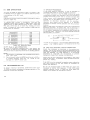
The following accessories should be included with the
tranceiver.
Instruction Manual (1350-2791-00) . . . . . . . . . . . . . . . . . . 1
Plastic Extension Feet with Screws
(JO2-0049-14) . . . . . . . . . . . . . . . . . . . . . . . . . . . . . . . . . . . . . . . . . 2. . .
Speaker Plug 1/8" ( E l 2 - 0 0 0 1 -05) .................. 1
7P DIN Plug (E07-0751-05) ........................... 1
Fuse (6A) (F05-6021-05) (U.S.A.) ................... 1
(4A) (F05-4022-05) (Europe) .................. 1
OPERATING LOCATION
As with any solid state electronic equipment, the TS-530s
should be kept from extremes of heat and humidity.
Choose an operating location that is dry and cool, and avoid
operating the transceiver in direct sunlight. Also, allow at
least 3 inches clearance between the back of the equipment
to any object. This space allows an adequate air flow from
the ventilating fan to keep the transceiver cool.
CAUTION:
Do not operate the radio in an RF Field greater than 6V RF.
Receiver damage may occur.
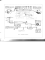
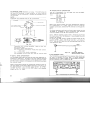
2.3 CABLING
(See Figure 2 - 1.)
GROUND
To prevent electric shock, and reduce the poss~bil~ty
of TVI
and BCI, connect the transceiver to a good earth ground
through as short and heavy lead as possible. Use ground
rods or metal cold water feedline.
NOTE:
A ground connection greater than 1/4 X away from the
transceiver may be a good DC ground, but NOT an RF
ground.
ANTENNA
Connect through a 5 0 ohm antenna feedline to the coaxial
connector on the rear panel.
KEY
If CW operation is desired, connect a key to the KEY jack.
Use shielded line or coaxial cable.
For fixed station operation, the TS-530s operates from
120V AC (U.S.A.) or 220V AC/250V AC (Europe). 50/60 Hz
power source capable of supplying 2 8 0 watts or more.
120V AC line model (U.S.A.)
A 6A fuse is used.
If you desire operation on 220V AC or 240V AC, it is
necessary t o change the power transformer connections
and the fuse.
See page 27.
220/240V AC line model (Europe)
This destination type is equipped with a voltage selector
switch on the rear panel.
A 4A fuse should be used.
Set the switch to your line voltage and use the correct
fuse.
NOTE:
The 220/240V AC model is preset t o 220V.
2.4 MICROPHONE
Attach the microphone connector to a suitable microphone,
as shown in Figure 2- 1. Be sure the microphone P l T switch
is separate from the microphone circuit, as shown. I t should
be noted that a microphone with a 3P plug using a common
ground terminal should not be used.
The microphone input is designed for 500R -- 50kU
microphones. The choice of microphone is important for
good speech quality. and .should be given serious
consideration. The crystal lattice filter in the transceiver
provides all the restriction necessary on audio response, and
further restriction in the microphone is not required. It is
more important to have a microphone with a smooth, flat
response throughout the speech range.
Follow the microphone manufacturer's instruct~onsfor connecting the microphone cable to the plug. With many
microphones. the push-to-talk button must be pressed t o
make microphone audio available. For VOX operation. this
unwanted feature may be eliminated. if desired. by opening
the mtcrophone case and permanently connecting the
contacts which control the microphone audio.
Headphones
Use headphones of 4 to 16Q irnpedance. The optional HS-4. HS-5
headphones best suited for use with
the TS-530s.
Stereo-type stet
phones can also be used.
p7
r=-"'""'
" ""
Microphone
Ellher a 1 0 1 or hlgh impedance
rn~crophone(50011 to 5 0 k W can be
used The P.T.T. s w ~ t c hshould
- - - be
-.
P.T.T. and VOX are available.
J
For CW operation. connect your key
s the bullt-in
r. an e x t e r n a l
can also be used.
t to the rear EXT
usmg the supplied
GND terminal
It IS recommended that a ground lead
be connected to the GND termmal at
the rear of the set t o prevent the
possibility of electric shock. TVI and
BCI Use as short and heavy a lead
as possible.
AC line source
See page 5. AC POWER
External VFO
Fig. 2-1 TS-530s Connections
Standard microphone sensitivity is within the range of - 5 0
dB to - 6 0 dB. If a microphone having a higher sensitivity
is used, the ALC and compressor circuits will not function
properly. In this case. insert in the mike line an attenuator as
shown in Fig. 2-1c. A typical MIC gain control setting is 12
o'clock. If you must run this control at 9 o'clock or less, use
an attenuator.
2.5 KEY
If CW operation is desired, connect a key to the KEY jack.
Use shielded cable, and a standard (mono or 2P) phone plug.
2.6 EXTERNAL SPEAKER A N D
HEADPHONES
Receive audio output from the TS-530s is 1.5 watts at 4 to
16 ohms. The TS-530s has a built-in SPEAKER jack on the
rear panel. The speaker may be an 8-ohm permanent-magnet type, 4 inches or larger. The internal speaker is disconnected when an external speaker is used. Headphones
should also be 4 to 1 6 ohms impedance. When headphones
are connected to the front-panel PHONES jack, the speaker
is disabled.
2.7 G R O U N D
To prevent electric shock. and reduce the possibility of TVI
and BCI. connect the transceiver to a good earth ground
through
as sh-ort and heavy a lead as possible.
-.
2.8 ANTENNA
Any of the common antenna systems designed for use on
the high frequency amateur bands may be used with the
TS-530s. provided the input impedance of the transmission
line is not outside the capability of the pi-output matching
network. The transmission line should be coaxial cable. An
antenna system which shows a standing wave ratio of less
than 2 : 1 when using 5 0 or 75 ohm coaxial transmission
line, or a system that results in a transmission line input
impedance that is essentially resistive, and between 15 and
200 ohms will take power from the transceiver with little
difficulty. If openwire or balanced type transmission line is
used with the antenna, a suitable antenna tuner with balun
is recommended between the transceiver and the feed line.
Methods of construction'and operating such tuners are
described in detail in the ARRL Antenna Handbook, and
similar publications. For operation on the 160. 7 5 and 4 0
meter bands, a simple dipole antenna, cut to resonance in
the most used portion of the bands, will perform satisfactorily. For operation of the transceiver on the 10, 15 and 2 0
meter bands. the efficiency of the station will be greatly
increased if a good directional rotary antenna is used.
Remember that even the most powerful transceiver is
useless without a proper antenna.
CAUTION:
Protect your Equipment
-
Use a LIGHTING ARRESTOR.
-
3.1 FRONT PANEL
9. N B LEVEL CONTROL @
This control adjusts the noise blanker circuit operating level
according to receiving conditions or noise level.
The symbol after the part name indicates:
@: Active only during reception.
@: Active only during transmission
No symbol: Always active
lo. AGC
SWITCH
@
This controls the AGC (Automatic Gain Control) circuit:
OFF .............. AGC disabled (no AGC).
FAST............ Normally used for CW operation.
SLOW .......... Normally used for SSB operation.
11. METER S W I T C H
1. PROC (SPEECH PROCESSOR) INDICATOR
@
This indicator, (light emitting diode), illuminates when the
PROC switch is turned ON.
2. VFO INDICATOR
The VFO indicator illuminates when the internal VFO
controls transceiver operation. The indicator is not lighted
during fixed channel or remote VFO operation.
3. C A L INDICATOR
@
The CAL indicator illuminates when the CAL switch is turned ON.
4. RF ATT INDICATOR @
This illuminates when the RF ATT is turned ON
5. METER
The meter monitors five different functions, depending on
METER s w i t c h p o s i t i o n . I n receive the meter i s
automatically an S-meter, and shows received signal
strength on a scale of 0 to 4 0 dB over S9. In transmit,
meter function depends on the position of the METER
switch. as described below. This is an average-responding
meter, NOT peak-reading.
6. VOX S W I T C H (T)
The VOX circuit is readied for voice operated transmit in
SSB or semi-break-in CW.
7. VOX G A I N (T)
This determines the transmit meter function:
ALC (Automatic Level Control)
Monitors internal ALC voltage, or the ALC voltage
feedback from a linear amplifier operated in conjunction
with the TS-530s. For SSB operation the ALC reading
for voice peaks should be within the indicated ALC
range. ALC voltage adjustment is made with the MIC
control for SSB and with the CAR control for CW.
IP (Plate Current)
In this position the meter monitors final tube plate current. The scale is calibrated from 0 to 3 5 0 ma.
(Output Power)
This monitors relative output power of the transceiver.
There is no meter scale for this position. Normally the
reading should be adjusted (with the RF METER
control) for a 2/3 scale reading.
( H ~ g hVoltage)
This position monitors the high voltage power supply.
The meter scale is calibrated from 0 to 10, indicating 0
to 1 0 0 0 volts.
STAND-BY S W I T C H
@
This two-position lever switch selects:
REC ............. The transceiver is receiving unless the
microphone PTT switch, or the VOX circuit is
activated.
SEND ........... Locks the unit in transmit.
13. VOX DELAY CONTROL IT)
The DELAY control adjusts the hold t m e for VOX or break-in
CW operation. Adjust for individual preference.
This controls sensitivity of the VOX (Voice Operated
Transmit) circu~t.
14. CAR LEVEL CONTROL (TI
8. N B S W I T C H @
With the push switch IN, the noise blanker circuit turned
ON reducing pulse-type (ignition) noise. Power-line, radar,
QRM and atmospheric "white" noises will not operate the
blanker. The noise blanker circuit operating level is
adjustable by the noise blanker control.
This controls carrier level during CW operation. Adjust the
CAR level so that the ALC meter points to the center of the
ALC zone. The ALC meter should not read beyond the ALC
zone.
1 5 . PHONES JACK @
2 2 . DIGITAL DISPLAY
The headphones jack allows use of a 4 to 1 6 ohm
headphone through a 1/4" phone plug When phones are
The d~gital display indicates operating frequency to the
used the speaker
IS
nearest 100 Hz.
disconnected
23. ANALOG DIAL SCALE
1 6 . M I C CONNECTOR
The four pln connector allows use of a mlcrophone w ~ t hPTT
F~gure2 - 1 B shows plug wlrlng
1 7 . M O D E SWITCH
The mode swltch selects type of emlsslon, and TUNE
TUNE
Thrs posltlon prov~desreduced carrler and
shorted key l ~ n efor transceiver tunlng (Input
power to the f ~ n a l sectlon IS reduced to
prevent tube damage durrng tune-up) Use
thls posmon to zero-beat an lncomlng CW
s~gnal
The mono-scale permlts d~rectanalog frequency readout
over the 0 to 5 0 0 kHz range, graduated at 1-kHz rntervals
Operating frequency equals the d ~ a (In
l kHz) plus the BAND
s w ~ t c hfrequency On MHz) An a d d ~ t ~ o n a5l0 kHz both
above and below the 500 kHz range I S also covered
24. M A I N T U N I N G
T h ~ scontrols the VFO. select~ngthe transceiver's operating
frequency. The indented knob is convenient for qulck
tunlng.
2 5 . LOAD CONTROL (TI
CW
Used for CW operation
USB .
.
. ..
Used for upper-sideband operation. International Amateur pract~ced~ctatesthe use of
T h ~ scontrols the loading of the network between the final
sectlon and the antenna Adjustment IS described in Section
4.
USB on and above the 1 0 MHz band.
2 6 . PLATE CONTROL (TI
LSB
.
. . . . Selects
lower-srdeband. International
Amateur practlce d~ctatesthe use of LSB on
and below the 7 MHz band.
1 8 . M I C GAIN CONTROL
%
Thls control adlusts mlcrophone a m p l ~ f ~ egain
r
for SSB
operatlon Adjust for an on-scale ALC read~ngon volce
peaks
19. NAR SWITCH (R)
With opt~onalfilters installed, the IF bandwidth can be
selected by the Narrow Swltch. The bandwidth varies with
filters being used. For details, refer to Narrow Switch on
T h ~ scontrols the plate tunlng of the f ~ n a lampl~flers CaIibratlon IS approxlmate
3
DRIVE CONTROL
Thls control tunes the plate tank clrcult of the 12 B Y 7A
drwer as well as the rece~ver'santenna and mrxer colls In
recelve the DRIVE control IS tuned for maxlmum senslt~vlty
( m a x ~ m u m S-meter deflect~on). and In transm~t for a
maxlmum ON-SCALE ALC read~ng These polnts occur
concurrently Tun~ngfor one also ach~evesthe other
2 8 . RIT/XIT INDICATOR
This indicator will light when the RIT switch or XIT switch is
ON.
page 16.
2 9 . RIT/XIT CONTROL
20. PROC (SPEECH PROCESSOR) SWITCH ( T )
This switch is used during SSB operation. Set the switch to
the ON position and the speech processor will be activated.
increasing the average talk power.
2 1 . RF ATT SWITCH (R)
With this s w ~ t c hON, A 2 0 dB attenuator IS inserted in the
antenna circu~t,protecting the RF amplifier and mixer from
overload on strong Input slgnals.
Thrs control allows the recelve frequency transmlt frequency
or both t o be sh~ftedw ~ t h o u uslng
t
the main tunlng control
W ~ t hthe RIT swltch ON, the RIT clrcult IS actlvated to s h ~ f t
only the recelve frequency
Wlth the XIT s w ~ t c hON, the XIT clrcult IS actlvated t o shlft
only the transm~tfrequency
When both swrtches are ON. both irequenc~esare shlfted
The center (0) posltlon equals no shlft
30. B A N D SWITCH
36. IF SHIFT CONTROL (R)
The 10-position switch selects all Amateur bands from 1.8
to 29.7 MHz. To select the 28.5 or 29.5 MHz bands, push
the t 0 . 5 switch ON.
Use the 1 0 MHz band for WWV reception.
A n A U X receive band is also available.
Coilpack (Receiver front-end) and PLL components must be
installed and aligned for the specific receive frequency range
desired.
During reception, the center frequency of the IF crystal filter
can be shifted 2 1.2 kHz facilitating adjustment of tone quality, or eliminating interference from nearby frequencies. For
normal operation. set t o the center detent position (click
stop).
+0.5 SWITCH
This switch is used in conjunction with the bandswitch.
Depress the switch with the bandswitch set to "28". and the
transceiver will operate in the 28.5 MHz band. When the
bandswitch is set t o "29". the transceiver will operate in the
29.5 MHz band. This switch has no function at any other
bandswitch position.
receiver
This switch energizes the built-in marker circuit.
Receive frequency can be calibrated at 2 5 kHz intervals
using this oscillator.
38. XIT SWITCH (T)
This push switch activates the XIT (Transmit Incremental
Tuning) circuit and the XIT indicator. By adjusting the XIT
control, the VFO transmit frequency can be varied 2 2 kHz
without changing the receive frequency.
39. RIT SWITCH (R)
32. A F G A l N (R)
This adjusts
clockwise.
37. C A L SWITCH (R)
audio
level.
Volume
increases
33. POWER SWITCH
This switches all power to the transceiver.
34. HEATER SWITCH
This switch turns the three transmitting tube filaments ON.
35. RF G A l N (R)
This adjusts receiver RF amplifier gain. Turn fully clockwise
for maximum gain and a correct S-meter reading.
This push switch activates the RIT (Receiver Incremental
Tuning) circuit, and the RIT indicator. By adjusting the RIT
control, the VFO receive frequency can be varied 2 2 kHz,
without changing the transmit frequency.
If, both switches are ON, both the transmit and receive
frequencies will shift simultaneously.
@ COOLING FAN
@
@ RFVOLT CONTROL
@
(3 ANTI VOX CONTROL
a
@ SPEAKER JACK @I
___--
1
!i?
REMOTE
.
CONNECTOR
@ GND LUG
@ SG SWITCH @I
@ AC POWER CABLE
$3 AC FUSE
B
Fig. 3 - 2 Rear Panel View
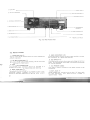
3.2 REAR PANEL
1. COOLING FAN
@
T h ~ sfan cools the RF amplifier section to Insure rehable and
efficient operation.
2. RF METER CONTROL @
This adjusts the R F output meter reading. Set for 2/3 scale
reading during CW transmission.
b-
3 . ANTENNA CONNECTOR
This SO-239 coax connector should be attached to a
suitable 50R antenna for transmitting and receiving.
4. BIAS CONTROL @
This adjusts the bias voltage to the 6 1 4 6 8 amplifier tubes.
Clockwise rotation increases the idling plate current.
Section 4 describes adjustment t o 6 0 ma.
5. G N D (GROUND) LUG
To prevent electric shock, as well as RFI and BCI. connect
the transceiver to a good earth ground.
6. SG SWITCH
@
This slide switch controls the screen grid voltage to the final
tubes. For neutralizing. switch OFF. The switch remains ON
for normal operation.
7. AC POWER CABLE
This cable is used to connect an AC power source to the
transceiver.
8. KEY JACK @
Using shielded line. connect a key to this 1/4" phone jack
for CW operation. Key o p e n - t e r m i n a l voltage i s
approximately - 65V.
12. REMOTE CONNECTOR
9. ANTI VOX CONTROL @
Adjust the control to prevent speaker output from tripping
the VOX.
This connector is used to interconnect a linear amplifier or
other accessory item. See page 2 4 for detail.
10. SPEAKER JACK @
The receiver audio output can be connected through this
jack to an external 4 to 16 ohm speaker. The internal
speaker is disconnected when an external speaker is connected.
This DIN connector is used to interface the KENWOOD
VFO-240 external VFO. The interconnecting cable is
provided with the VFO.
FUNCTION
PIN
This fuse protects the transmitter power supply against short
circuits. Never use a higher amperage fuse than specified: it
will eventually cause extensive damage. If the fuse blows,
try t o determine the cause before replacing.
For 120 volt operation use a 6 ampere fuse and for
220/240 volt operation. a 4 ampere fuse.
11. EXTERNAL VFO CONNECTOR
PIN
13. AC FUSE
14. PREDRILLED HOLES
These are provided for owner-installed switches or
connectors.
FUNCTION
1
VFO slgnal
5
VFO control
2
Relay control
( + on transm~t)
6
D~splaycontrol
3
t9V
7
Ground
4
CW freq shlfl control
8
t 12V
VOLTAGE SELECTOR SWITCH
The 220/240 VAC line model (in Europe) is equipped with a
voltage selector switch on the rear panel.
Set this switch to suit your line voltage, if necessary.
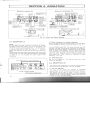
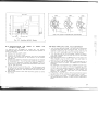
(2) RF G A l N CONTROL
(5) IF SHlFT
RF GAlN IS controlled by changing the AGC threshold
voltage. Adjust the RF GAlN so the S-meter does not
deflect excessively. This also reduces nolse d u r ~ n g
reception. For normal operation, this control should be turned fully clockwise for maximum sensitivity.
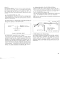
The IF SHlFT control is used to shift the passband of the IF
fdter without changmg receive frequency. By turning this
control in either direction, the IF passband is shifted as
shown in Fig. 4-3.
The IF SHlFT is effective in eliminating interference when
the receive signal is superimposed on nearby signals during
operation in both SSB or CW mode.
Max~mum" S m e t e r readmg
of an incoming signaL
*:
R F GAlN
J
Turned ~n0 d ~ r e c l ~ o n
Full
S~gnalsweaker
than this level
are attenuated.
\
Po~nterdeflect~onwith
RF gain control adjusted
Counterclockwise.
1
Turned ~n@ d ~ r e c t ~ o n
I F f ~ l t e rpassband
character~stlc
I
clockwise
position
e8
t
R F GAIN
0
I0
Turn
counter-
Fig. 4-3
RF GAlN Control Operation
clockwise
(3) AGC (AUTOMATIC G A l N CONTROL)
Set the AGC switch to the appropriate position: Generally
for SSB. SLOW, for CW FAST. and for very weak signals, the
AGC may be turned OFF.
Simultaneous Use of the RF G A l N CONTROL and AGC
Switch
If a strong signal (such as a local station) appears in the vicinity of the intended receive signal. the S meter may show
unusual deflection due to the AGC voltage developed from
the strong disturbing signal. If this occurs, turn the RF GAlN
down so the meter pointer remains at about the or~ginal
deflection peak and turn the AGC switch OFF. This w ~ l l
eliminate the unwanted AGC voltage and permit clear
IF SHIFT
Turn In
IF SHIFT
d~rectlonto
IF SHIFT
Turn In @ direct~onto
elmmate mterference
el~m~nate
~nterference
from s~gnalB
from s~gnalA.
Fig. 4-3 IF SHlFT CONTROL
reception.
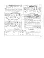
(a) USB MODE (10 MHz and above)
First set the RIT/XIT control to center, and turn the RIT
switch ON.
The RIT/XIT control allows shifting the receive frequency by
approximately + 2 kHz without changing the transmit
frequency.
With the RIT switch ON, the receive frequency can be
adjusted by uslng the RIT control.
With both the RIT and XIT switches ON, both the transmit
and receive frequencies can be shifted.
For XIT switch operation, refer to Section 4.4 "Transmission
(11)".
NOTE:
When the RIT is ON. transmit frequency is different from the
receive frequency. For normal operation, leave the RIT
switch OFF. It should be turned ON only when needed.
Adjust the IF SHIFT control in the ( + ) direction and lower
frequencies are cut. Adjust the control in the ( - ) direction
and high frequencies are cut.
(b) LSB MODE (7 M H z and below)
+
Adjust the control in the ( ) direction and higher
frequencies are cut. Adjust the control in the ( - ) direction
and low frequencies are cut.
(C) CW MODE
By using the IF SHIFT in conjunction with the RIT, tone
quality can be adjusted.
(6) NARROW SWITCH
In the NARROW position without optional filters no signals
are received. Optional filters (CW: YK-88C. YK-88CN. SSB:
YK-88SN) for NARROW operation are available for improved radio interference rejection. Any two filters can be
used according to your application. When two CW filters,
YK-88C and YK-88CN are used, the WIDE position in CW
mode is 0.5 kHz.
(7) NOISE BLANKER (NB)
For pulse type noise. such as generated by automotive ignition systems. turn the NB switch ON. Adjusting the NB
LEVEL control varies the blanker's threshold, eliminating
even low level noises.
If high level s~gnalor noise is present on an adjacent
frequency, do not use excessive NB threshold LEVEL as it
may distort the received signal.
If you are operating near other strong signals, use the RF
ATT along with the noise blanker level control.
4.3 TRANSMISSION (I)
This section covers adjustment of the transceiver for
transmission.
Refer to Fig. 4-1 for initial transmitter switch settings. Set
the main tuning to the desired operating frequency. (Refer
to Table 4-1 for a summary of the following.)
Fig. 4-4 Testing w i t h a Dummy Load or Power Meter
1. Connect a 5OQ antenna for the band you will operate or a
dummy load. and connect a key. SWR must be 2: 1 or
better. The life of the final tubes is directly related to
the SWR of the antenna, and to the length of tuning
periods.
2. Turn POWER and HEATER Switches ON.
3 3 . Place the MODE switch to SSB, METER switch to Ip.
4. Place the SFAND-BY switch to SEND and adjust bias to
6 0 mA with the BIAS control on the rear panel, Fig. 45.
CAUTION:
If the plate current is higher than 6 0 mA do not leave the
stand-by switch on for more than a few seconds. Excessive
plate current shortens the life of the final tubes.
CAUTION:
DO NOT turn the BANDSWITCH while the transceiver is in
transmit mode.
Fig. 4-6 Adjusting Final Tube Bias
4.5.
Place U
E switch t o Z E . METER switch
to ALC.
Peak the DRIVE control. If the meter pegs or goes out
of the ALC range, reduce the CARRIER control setting
for an on-scale reading. (the CAR control is a level
adjustment, while the drive control is a resonating
adjustment.) Fig. 4-6
-
Ouickly adjust the PLATE control and
then the LOAD control alternately to
--
NOTE:
The TUNE position permits tuning of the final tank circuit at
reduced power without danger to the tubes. In the TUNE
position, the screen voltage to the finals is reduced
approximately 50% and the keying circuit is closed.
Adjust DRIVE control for
maximum on-scale meter
deflection.
I
~
$
Fig. 4-8 Final Tuning
9 the-.
6. Place t h e m switch t o and
be typically only about 5 ma. (
Fig. 4-7
m)
o
Dip will
w and p e a k t h e
# 7. Place t h e w t o =and peak the LOAD control.
.% 8.
Fig. 4-6 Peaking the Drive Control
*9.
Place the @ode switch to CW, M s r ! switch to Ip. Close
the key and IMMEDIATELY r e d i ~the PLcontrol.
Reduce the carrier control setting if Ip reads over
265ma. Open the key.
Place the meter switch to RF.
Close the key and repeak the LOAD for maximum RF
output. You may at your option also redip the PLATE for
maximum RF output. Fig. 4-8
Open the key. You are tuned up for CW operation. If
necessary, adjust the RF METER control on the rear panel to bring the output reading to about 2/3 scale.
This is a meter adjustment. not an output adjustment.
NOTE:
Dip point may not always coincide with maximum output,
because neutralization is accomplished on the 10 meter
band.
For this reason, you may simply adjust both the PLATE
and the LOAD controls for maximum output as described
in both tune-up procedure and summary Table 4-1.
6
Adjust PLATE control for dip.
Fig. 4-7 Plate Adjustment e-
Table 4-1. Summary of Transmitter Tuning Procedure
MODE Switch
METER Switch
Stand-by Switch
USE or LSB
IP
REC+ SEND
TUNE
A LC
REC+ SEND
Procedure
Adjust BIAS control for 6 0 ma.
Peak the RF reading with the PLATE and LOAD
controls.
TUNE
RF
REC+ SEND
Peak RF output by alternately adjusting the
CW
RF
REC+ SEND
PLATE and LOAD controls.
(1) SSB OPERATION
(1
Tune the TS-530s as described in steps 1 through 9. Set
the MODE switch per Table 4-2, to USE or LSB and connect
In DX (long distance) operation, it may be desirable to
increased talk-power by using the speech processor.
The speech processor in the TS-530s combines an audio
a microphone to the MIC input.
compression amplifier with changes in ALC time constant to
SPEECH PROCESSOR
NOTE:
provide extra audio punch and to increase average SSB
International Amateur practice dictates using USB or LSB as
output power, while suppressing sideband splatter.
To
activate. turn on the PROC switch, and readjust mic gain.
shown in Table 4-2.
Operated as described. distortion will be minimum.
To operate SSB. connect a microphone. (The Key and
CARRIER control have no effect in SSB mode.) Place the
MODE switch to SSB, METER switch to ALC. Adjust the
MIC gain control for an on-scale ALC reading on voice
peaks. (Disregard RF and Ip meter readings in SSB-they are'
not accurate or relevant.)
I
I
I
1
1.8 MHz Band
3.5 MHz Band
I
I
LS B
LS B
7
MHz Band
LS B
10
MHz Band
USB
14
MHzBand
USB
18
MHzBand
21
MHzBand
I
I
USB
USB
24.5 MHz Band
USB
28
USB
MHz Band
I
I
However, tone quality will be affected.
disabled
When a high-output microphone is used, input overload and
distortion will result. To prevent this, use an attenuator in
the microphone circuit as shown below, or connect a 10 33 kl2 resistor (depending on microphone used) across the
microphone input. ("Normal" mic control setting should be
approximately 12 O'clock).
10k
I
I
It is therefore
advisable to conduct normal operation with the processor
-
77;
33 kfl ldependmg on mlcropone used )
from m~crophone
the MIC connecter
The MC-50 m~crophoneIS recommended (Microphone sensitivity: - 55 + 3 dB for approx. 5 cm distance to the rnic.)
TABLE 4 - 2 Mode By Band
PTT (Push t o talk) OPERATION
(2) VOX (Voice Operated Transmit) OPERATION
By using a microphone equipped with a PTT switch, the
transceiver is ready for P l T operation. To key, depress the
PlT switch with the stand-by switch left in the REC position.
NOTE:
1. Transmission is impossible with the BAND switch set to
AUX, 18 or 24.5.
2.
Do not transmit when the BAND switch is set to AUX or
is midway between AUX and 1.5.
Doing so will
damage the 12BY7A driver tube.
Adjust the transceiver as described in the previous paragraph. Flip the VOX switch on and while speaking into the
microphone, increase the VOX GAIN control until the VOX
relay just operates. For VOX operation it is sometimes
desireable to close-talk the microphone to prevent
background noises from tripping the transmitter.
Check that the ALC reading for voice peaks is still within
range on the meter. If necessary. adjust the MIC control for
proper ALC reading.
If the VOX circuit is activated by speaker output, adjust the
ANTI-VOX control (on the rear panel) as necessary for
proper VOX operation.
4.4 TRANSMISSION (11)
To obtain maximum transmitter performance from your
TS-530s you should understand the proper operation of the
following controls and switches.
Do not use excessive VOX or ANTI VOX gain more than
necessary to control VOX operation. If the VOX circuit
transfers between words. or holds too long. adjust the
release time constant by the DELAY control.
(3) XIT
OPERATION WITH C W FILTERS (OPTION)
By using XIT, transmit frequency can be shifted independent
of receive frequency.
With the XIT switch ON, the XIT is controlled by the RIT/XIT
knob and transmit frequency can be shifted by about k 2
kHz. When both the RIT and XIT switches are ON, both
receive and transmit are shifted without adjusting the main
tuning.
(4)
cw
OPERATION (Fig. 4-91
Tune and load the TS-530s as described in Sections 4.3.
Using shielded line, connect a key to the rear panel KEY jack.
set the MODE switch to CW, and set the stand-by switch to
SEND for transmitting.
CW transmission is automatically monitored through the
transceiver's speaker. Sidetone audio gain can be adjusted
through the opening in the bottom cover.
Set the IF SHIFT to its center position and the RIT OFF.
Adjust the main tuning for maximum S-meter deflection.
Receive signal pitch will be about 8 0 0 Hz, indicating correct
tuning. For optional CW filter information see page 23.
KEY CONNECTION (Fig. 4-10)
Your key should be connected as illustrated in Fig. 4-10.
When using an electronic keyer. make sure that polarity is
correct. Use shielded line from the key to transceiver.
NOTE:
When using an electronic keyer, set polarity of the keyer for
NEGATIVE keying.
- 65V
Use shielded cable.
4
To Key
I
Displayed receive
frequency
I/
CND
Real transmit-receive
frequency
(D~splayedin transmission)
Before connecting.
check that polarity is
correct. The KEY jack
provides - 65V.
Beat frequency
800 Hz
Fig. 4-10 Key connection
Fig. 4-9 CW ZERO BEAT
SEMI-BREAK-IN OPERATION
OPERATION WITHOUT CW FILTERS
To receive CW. set the IF SHIFT control t o its center position
and the RIT switch t o OFF. Adjust the main tuning for about
an 8 0 0 Hz beat and your transmit frequency will be tuned
(zeroed) to the transmit frequency of the station you are
receiving. If the 0 beat cannot be obtained easily, adjust the
IF shift knob. then return the mode switch to CW. The
transmit frequency of the unit is adjusted to that of the mate
station. You may now adjust the RIT for a pitch which suits
your preference. If interference is encountered, adjust the IF
SHIFT. For more convenient and effective CW operation,
use of the optional CW filters is recommended.
The TS-530s has a built-in side-tone oscillator to permit
semi-break-in operation. besides the normal CW operation.
~ u r i nsemi-break-in
~
operation, the transceiver is set in
transmit mode when the key is depressed, and returns to
receive mode when the key is released. For semi-break-in
operation. place the STANDBY switch to REC and turn the
VOX GAIN control ON. Adjust the DELAY control for your
preference.
4.5 DIGITAL DISPLAY CALIBRATION
4.6 ANALOG DIAL CALIBRATION
Connect the antenna and set the BAND switch to WWV.
Turn the main tuning dial to receive 1 0 MHz WWV. Adjust
the dial until a low-frequency beat is heard. A marker signal
will be superimposed on the WWV signal. A double beat
(two beat signals of high and low frequencies) will now be
heard. Adjust the IF shift for low AF response. While
receiving this double beat, adjust the Standard oscillator
trimmer through the reference frequency adjustment access
opening (on the bottom of the TS-530s) so the two beats
are heard as a single beat. Repeat this procedure 2 or 3
times. This completes calibration of the Digital Display.
After calibration turn of the CAL switch.
The dial scale is graduated at 1 kHz intervals. One revolution of the main dial covers 25 kHz. To calibrate the scale,
turn the MIC control t o the CAL position. Zero-beat in either
SSB or CW mode. Hold the main tuning knob from rotating
and slip the calibration ring t o the nearest major (5 kHz)
graduation. The dial is now calibrated.
NOTE:
For exact frequency, read the Digital Display.
Access (STD.OSC. F.ADJ)
._---
Insulated tuning tool
Fig. 4-1 1 Digital Display Calibration
I
I
Fig. 4-12 Analog Dial Calibration
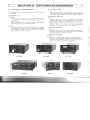
PHONE PATCH
MICROPHONE
PC-1: (Available only where phone patch operation is
legal.)
Hybrid phone: patch with VU meter for null and
audio gain measurements.
The PC-1 Phone Patch provides connection between
a transceiver and a telephone line.
Providing excellent performance, it is designed with
high isolation between receive input and transmit
output.
Its compact design permits easy installation in a
limited space.
8 HEAD PHONES
HS-4: 811 communications headphones.
HS-5: Deluxe 8Q headphone set.
HS-6: Deluxe 12.5Q lightweight headphone set.
MC-50: Desk Microphone ( 5 0 k9/500R)
MC-35s: Noise Cancelling Hand Microphone ( 5 0 kQ)
MC-30s: Noise Cancelling Hand Microphone (500i2)
FILTER
SSB:
CW:
YK-88SN : 1.8 kHz SSB filter
YK-88C : 500 Hz CW fllter
YK-88CN : 270 Hz CW filter
DIGITAL WORLD CLOCK
HC- 10:
The HC-10 is a highly advanced world clock with dual
display which can memorized 1 0 world major cities and
2 additional regions.
KB-1
Deluxe flywheel VFO tuning knob.
PC- 1
HS- 5
HC-10
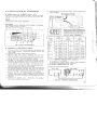
5.2 INSTALLATION OF ACCESSORIES
10. Apply power and verify your work. Filter installation is
now complete.
REMOVING THE CABINET (See Fig. 5-1)
Figure 5-1 illustrates cabinet removal. Remove the eight
top-cover and eight bottom-cover screws and lift away the
panels.
NOTE:
This product uses metric hardware.
CAUTION:
The speaker lead is attached to the chassis, so be careful
when removing the top cover.
The lead can be unplugged. if necessary.
When two CW filters, YK-88C and YK88CN are used. mount the YK-88C in the
SSB NARROW FILTER position and the
YK-88CN in the CW FILTER position.
Jumper connectors A and B (as shown)
according to the optional filters used.
J
Optional
Filter
Jumper
connector
Fig. 5-2 Filter installation
SSB
CW
NAR SW
NAR SW
YK-88XX
Without
filter
~ptional
Fig. 5-1 Removing the Case
SN
C
OPTIONAL FILTER INSTALLATION
1. Using a number 2 Phillips screwdriver. remove the top
cover (eight screws). Unplug the speaker and set the
cover aside.
2. Remove the bottom cover (eight screws).
3. Remove the six screws holding the IF unit
X48- 13 10-00 and swing the printed-circuit board over.
4. Using a 45-W (or less) soldering pencil, clear the six holes for the filter, if they are filled with solder.
5. YK-88s. C, or CN there is no polarity to the filter. Install
the filter into its position on the IF unit. Solder the two
mounting tabs and the four input and output pins to the
circuit boards. Solder sparingly, and heat the connections only long enough to insure a good solder joint.
Don't overheat the filter or circuit board.
6. Carefully inspect your soldering. Be certain that all pins
are actually soldered. and that you have not soldered
across any spots on the board or between any of the
pins on the filter. Clip the pins flush to the board.
7. Replace the IF unit. Make certain no wires will be
pinched underneath the board. Replace the six screws.
8. Move the A and B connectors as illustrated, following
Table 5-1.
9. Reinstall the bottom cover. Reconnect the speaker
lead, and reinstall the top cover.
C
+ CN
1 CW I SSN 1 2.4 kHz
Table 5-1 Optional Filter Selection
No reception in this position
In transmission, the SSB (WIDE) filter is used regardless
of MODE or NAR-WIDE switch positions.
VFO-240 CONNECTION (Fig. 5-31
Connect the VFO-240 as shown.
I
I
Fig. 5-3 VFO-240 CONNECTION
8 REMOTE CONNECTIONS
8 PHONE PATCH OPERATION
Fig. 5-4 shows the REMOTE connector. This DIN plug can
be used for attaching a linear amplifier or other external
accessories to the transceiver. Always use shielded line for
all functions.
The PC-1 Phone Patch can be used with the TS-530s.
Recommended settings are:
NOTE:
ALWAYS use sh~eldedlme for all connections.
ALC IN put
From STBY switch
From AF out ( 8 R l
IPTT circuit for foot
r--
---- --
I
c
I
I
I
1
I
1
I
I
I
PC-1
RX Gain
4
TX Gain
4
Null as necessary
TS-530s Vox Gain
1
AF Gain
4
Mic Gain
5
Anti Vox Max
Most other phone patches will work satisfactorily without
any modification to the radio, requiring only an external
speaker connection, and that the Mic line be run through the
patch.
For those operators who desire a Patch input similar to the
TS-520s or TS-820s. an input connection and terminal
must be added at the Mic input preamp circuit.
I
,
< T
1
I
GND
Use a 100 k l l resistor in series. with a 1 0 kQ to ground on
the input side of the 1 0 0 k i l resistor. Use shielded line, an3
connect as follows:
On the IF unit X48-1310-00 install the fixed divider at the
junction of R61, 1Ok n. C50. 100 pF and C51, 1 pF (input of
Q1 1). Add an RCA jack at one of the predrilled hole on the
rear panel for input.
Fig. 5-4
Operation with a linear amplifier. Refer to Fig. 5-4.
Pin 6 ALC input
Connector metal shell ground
Pin 2 Ground to connector metal shell and control
line braid.
Pin 4 Control line center conductor.
Use shielded line for both ALC and RL (control line).
~ 5-5
i ~
.Optional Special
Phone Patch Input.
EXTENSION FEET
SSTV, AFSK OPERATION
The TS-530s will adapt very well t o slow scan television or
AFSK RTTY operation. For SSTV. the only cabling required
are connections between the MIC connector of the TS-530s
and the camera output. and between the SPEAKER jack and
the monitor input.
The TS-530s is provided with two extension feet which can
be used to elevate the front panel. In some operating
positions the tilt makes it easier to read the dial and meter.
Fig. 5 - 6 shows how t o install the feet.
I
When transmitting. adjust the transmitter output so that final input power is less than 100W (less than 125 mA Ip). or
for approximately 1/2 of normal output power, for AFSK,
connect the T.U, output to the MIC input, and speaker
output to the T.U. Input.
Fig. 5-6 Attaching t h e Extension Feet
=
SECTION 6. MAINTENANCE AND ALIGNMENT
CAUTION:
DANGEROUS HIGH VOLTAGES .ARE PRESENT WITHIN
THE CASE OF THE TS-530s WHEN THE TRANSCEIVER IS
TURNED ON.
EXERCISE EXTREME CAUTION TO AVOID ELECTRIC
SHOCK.
6.1 GENERAL
Your TS-530s has been factory aligned and tested to
specification before shipment. Under normal circumstances
the transceiver will operate in accordance with these
operating instructions. All adjustable trimmers and coils in
your transceiver were preset at the factory and should only
be readjusted by a qualified technician with proper test
equipment.
Attempting service or alignment without factory authorization can void the transceivers warranty.
RIT ZERO (IF UNIT)
When the RIT circuit is turned on, and the RIT control is set
to zero, the receive frequency should be exactly the same as
the transmit frequency. If the frequency is not the same.
adjust the RIT zero preset control, VR5.
To zero the RIT, turn on the calibrator and tune the VFO for
about a 1000 Hz calibrator tone. Turn the RIT control to
zero. Turn the RIT switch ON and adjust VR5 for the same
1000 Hz tone. Push the RIT switch ON and OFF to be sure
the tones are identical.
The knobs, front panel and cabinet of the TS-530s are likely
to become soiled after extended use. The knobs should be
removed from the transceiver and cleaned with a neutral
soap and warm water. Use a neutral soap (not harsh
chemicals) and a damp cloth to clean the cabinet and front
panel.
FUSE REPLACEMENT
Fig. 6-1
Coil Pack Locations
w
FRONT Panel
F A N MOTOR LUBRICATION
Every 6 months dust out the final compartment, and apply a
few drops of light machine oil to the front and rear fan motor
bearings.
BAND Switch
1.5
Frequency for
adjustments
1.9
MHz
WARNING:
Be certain to disconnect power, and to discharge high
voltage before servicing in the final compartment.
6.2 SERVICE POSITION
The TS-530s should be placed on its side, with the final
section up, for any alignment or service. This position
permits adequate ventilation for the final tubes as well as
easy accessibility to the modules. Most of the described
adjustments can be made without removing the boards from
the transceiver.
1
6.3 RECEIVER ADJUSTMENTS
CLEANING
When the fuse blows, there is some cause. Be sure to find
the cause before attempting operation. Use a 6 amp fuse
for 120V AC operation and a 4 amp. fuse for 220/240V AC
operation. Under no circumstances use a higher amperage
fuse than specified: This can cause extensive damage.
Also. the warranty will be void if an oversized fuse is used.
z
Table 6-1 Alignment Order
8 ADJUSTMENT OF ANT A N D M I X COILS
8 TRANSMIT DRIVE COlL ADJUSTMENT
(RF UNIT)
The ANT and MIX coils are included in the coil pack unit.
Use the 25 kHz calibrator as a signal. Connect a 50R dummy
load to terminate the receiver input. Set the DRIVE control
to 12 o'clock. Adjust the ANT and MIX coils for maximum S
meter deflection. following the frequency table. Start with
the 1.8 MHz band and then proceed to other bands. To adjust the 10m band. use only 28.8 MHz in the 28.5 MHz
band.
(RF UNIT)
The drive coils are part of the coil pack unit. Set the SG
switch on the rear panel to OFF and center the DRIVE control (12 o'clock). Set the METER switch to ALC and the
MODE switch to CW or TUNE.
With the standby switch in the SEND position. adjust the
drive coils for maximum ALC deflection for each band using
the same frequency and in the same order as for adjustment
of the ANT and MIX coils.
During adjustment, adjust the CAR control so there is just
enough injection to swing the ALC meter.
8 ADJUSTMENT OF RECEIVE IF COILS
(RF AND I F UNITS)
Receive a marker signal using any frequency. Adjust the
DRIVE and the main tuning for maximum S meter deflection. Adjust T2 on the RF unit, L2, L5, L6, L7 and L10 on the
IF unit for maximum S meter indication. DO NOT adjust L8.
S METER ADJUSTMENT (IF UNIT)
Disconnect the antenna with the transceiver in receive
mode. Zero-point adjustment:
Adjust VR1 for meter pointer zero indication. If a standard
SIGNAL GENERATOR (SSG) is available, adjust VR2 so the Smeter indicates "S-9". at 14.175 MHz for a 40 dB (50pV)
signal.
6.4 TRANSMITTER ADJUSTMENTS
TRANSMITTER NEUTRALIZATION
(See Internal View Bottom)
The TS-530s requires neutralization every time the final
tubes are changed.
Tune up the TS-530s into a 5 0 ohm dummy load at 28.5
MHz for CW operation as described in Section 4 . Set the
SG switch to OFF and place a sensitive RF milli-voltmeter
across the dummy load. Flip the stand-by switch to SEND
and adjust TC1 (at the bottom of the final section) for a
minimum reading on the voltmeter. After the final section is
neutralized, flip the stand-by switch to REC and slide the SG
switch ON.
A receiver tuned to 28.5 MHz works very well for neutralizing if an RF voltmeter is not available. Instead of tuning for
a minimum voltage, tune for a minimum S-meter reading.
NOTE:
Since the drive tube operates into a fixed load (the finals) it
is not always necessary to replace this tube when replacing
the finals.
-
-
CAUTION:
Neutralization of the final section should be carried out with
the chassis shield in place. Dangerous high voltages are
present in the final section when the transceiver is turned
on. Use an insulated tool to make this adjustment.
8 TRANSMIT I F COlL ADJUSTMENT (RF UNIT)
Using any frequency, place the transceiver in transmit mode
in the CW or TUNE position. Adjust T4 on the RF unit for
maximum ALC deflection.
8 CARRIER BALANCE ADJUSTMENT (IF UNIT)
With a 509 dummy load connected to the ANT terminal,
adjust for maximum output at 14.175 MHz. Reduce mic
gain to zero. Set the transceiver in LSB mode and adjust the
RF METER control on the rear panel for maximum
sensitivity. The RF meter will deflect if the carrier is unbalanced. To balance the carrier. alternately adjust trimmer
TC1 and trimpot VR4 until the meter indicates minimum.
Switch to USB mode and if the pointer deflects, readjust so
the pointer deflects equally for both LSB and USB.
8 ADJUSTMENT OF SIDE TONE LEVEL (AF UNIT)
Adjust VR 1 to your preference.
6.5 TRANSMITTING ON WARC BANDS
(Fig. 6-2)
As supplied, the TS-530s will receive but not transmit on
the 17, and 12 meter WARC bands. If transmit capability
is desired, a minor wiring change is required.
1. For 2 bands: Break the line between the RF unit
X44-1360-01, connector # 6, Pin # 1 (TOF terminal)
and AF unit X49-1 150-00, connector #7, Pin # 4
(TOF terminal).
2. Or, for individual Bands: On the RF unit X44-1360-01:
Band
1 8 MHz
24.5 M H z
Remove (or Cut) Part
Top view
Fig. 6-3 Power Transformer Connection
I
RF unit
Fig. 6-2 Enabling WARC Bands
6 . 6 OPERATION O N 2 2 0 V or 2 4 0 V A C
(U.S.A.) (Fig. 6-3)
To operate the TS-530s on 240V AC. the power
transformer split primaries must be rewired from parallel to
series connection.
1. Unplug the AC power cable.
2. Remove the bottom cover.
3. Remove the jumper wires between the two @ terminals
and two 120 terminals on the bottom of the power
transformer.
4. Connect the adjacent 120 and @ terminals at the middle
of the transformer. This will provide 240V AC operation.
For 220V AC operation, connect the adjacent 120 to 9
winding and move the white lead and bypass caps from
120 to 100 terminal.
5. Cahnge the AC fuse from 6A to 4A. Tag the power cord
at the back of the radio to indicate that the transformer is
strapped for 240V AC, and the power fuse should be 4A.
and not 6A.
6. Replace the bottom cover and reconnect power to verify
your work.
TS-530s ANALOG DIAL ADJUSTMENT
1. Turn the main dial fully CCW. The red cursor should line
up with the VFO start mark on the sub-dial. If it does not,
remove the main knob (2 mm allen), loosen and line 12
mm nut up the scale start point to the red cursor.
2. Turn the main knob to 5 0 kHz analog. Adjust the aluminum slip sub-dial to line up with any one of the larger
black dial marks.
3. Note the digital error: If it is MORE than 2 kHz adjust the
VFO trimmer cap TC1 (front under the seal tape) to
exactly 50.0 on the digital readout.
4. Turn the main knob to 450 analog. If the digital error is
less than 2 kHz it is in spec. If the digital error is greater,
proceed:
For instance if the digital error is 14.454.0 (plus 4 kHz),
multiply the error times 4 (16 kHz) and adjust the VFO
timmer cap to the desired frequency (14.450.0) LESS the
error, or 14.434.0. Next adjust the VFO inductor L3
(center under the seal tape) back up to the desired
frequency of 14.450.0.
5. I f the error in step 4 was in the minus direction, reverse
the direction of the correction adjustment in step 4.
6. VFO linearity final check: The digital readout and analog
dial should agree to within +2 kHz at every 100 kHz dial
point.
BUFF AMP
ZSC1815
AMP
JIPCI 158
AMP
2SC1815
BM
I F AMP
BUFF AMP
TX MIX
DRV AMP
RE PWR
61468 * 2
yA&+
-
METER AMP
ZSA1015
METER AMP
ZSK19
ALC TIME CONST
2SK30
VOX DELAl
METER
NB GATE
IS1587XA
NB FILTER
IF AMP
2SK125
RX MIX
2SK125X2
BUFF AMP
2SK125
RF AMP
3SK73
ANTI VOX
AF AMP
DET
1
I
1
AGC LINE
BUFF AMP
2SK19
NOISE AMP
2SC46OX 2
NOISE AMP
ZSC460
NB GATE DRIVE
ZSC1815
I
NJM78L05A
NB AGC AMP
ZSC945
5v
CAR
OUT
MARKER
OUT
VCO
OUT
I-
I
I
PLL UNIT
n
CAR FREQUENCY
vco
FREQUENCY
1
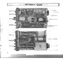
INTERNAL VIEW
B
~ n m . m ~ ~ ~ ~ ~ ~ m . m ~ . ~ ~ ~ ~ ~ n ~ ~ ~ ~ ~ ~ ~ ~ ~ ~ n u - ~ ~ ~ ~ ~ ~ ~ ~ ~ ~~ n
~ ~ ~ ~~ ~. n ~ ~~ ~n ~. ~
~ ~~ ~~ ~~ ~. ~n ~~ ~~ s. ~~ ~r ~n ~~ ~~ ~~ . ~~ n~ m
~
FINAL UNlT
(X56- 1 380-00)
NEUTRALIZAT
RECTIFIER UNlT
(X43- 1370-02)
POWER TRANSFORMER
REFERENCE FREQUENCY
ADJ. TRIMMER
(X48- 1 3 t 0-00)
POWER TRANSFORMER
-FAN
I*
*
A
61468
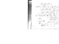
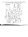
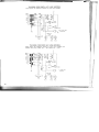
TS-530s SCHEMATIC DIAGRAM
PLL UNIT (X50-1680-01)
~~~~~~~I~IU-I*U.~~I~-~~~-~~III.~III.I*I**I*IO(~-IO(~~D-DI~~.~~~~~))IIII~III-IO)IO)III.II*.-UIII.I)IIIIYDYDIIILILE~(..E~(..UI.OOI).I)
..
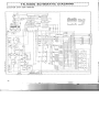
TS-530s SCHEMATIC DIAGRAM
.
.
I
)
7
5.11...m~~. I I ~ ~ . ~ I ~ I ~ ~ ~ ~ I I ~ ~ ~ ~ I I ~ ~ ~ I I I ~ ~ ~ ~ M I I I ~ ~ ~ I I ~ ~ ~ I U I ~ ~ ~ ~ I ~ . ~ ~ ~ I ~ ~ ~ I I I I ~ I I I ~ ~ ~ ~ I ~ ~ ~~ ~~~~. I~I ~I IHO~~~. M
~ U~ Y~ ~* .U~ -U~I ~
* .I ~I ~
Y I* ~
Y -* ~
UU
) *~. ~
H )-*~. IHI I ~
L ~- U
~ .U
- *~I ~
I IU~ U
~U
~~
U ~UY* Y* Y
. .W
. ~
~ *I ~
. ~
~~Y
~~~~~I
COUNTER UNIT (X54-1540-00)
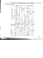
TS-530s SCHEMATIC DIAGRAM
AF UNlT (X49-1150-00)
N N N N N N N
i
i
f
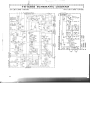
VFO UNlT (X40-1170-00)
TS-530s 220/240V A C L l N E M O D E L
Place S23, AC selector switch to your line voltage.
h@-7
220
50/60Hz
/ 240 VAC
1
&
R28 33
1 /2W
TS-530s 120/220V A C LlNE M O D E L
Place S23, AC selector switch to your line voltage and
replace the fuse (120V AC -+ 6A. 220V AC -+ 4A).
!~2
,
POWERS W '
120 / 220 VAC
50/60HZ
w 9 $9
FAN
PLI
PL2
PL3
I
Model TS-530s
Serial No.
Date of Purchase
/
/
Dealer
A product of
TRIO-KENWOOD CORPORATION
17-5, 2-chome, shibuya. shibuya-ku Tokyo 150, Japan
!
1
I
TRIO-KENWOOD
COMMUNICATlONS
1 1 1 1 West Walnut Street. Com~ton.California. 9 0 2 2 0 , U.S.A.
TRIO-KENWOOD COMMUNICAllONS, OmbH
D-6374 Steinbach TS. lndustriestrasse 8A. West Germany
TRIO-KENWOOD ELECTRONICS, NmVm
Leuvensesteenweg 5 0 4 . 8-1 9 3 0 Zaventem, Belgium
TRIO-KENWOOD CAUSTRAUAI PlVm LTD.
4 E Woodcock Place, Lane Cove N.S.W.'2066. Australia
Q35302 PRINTED IN JAPAN 850-2791-00 ( G )@@