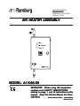
1
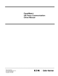
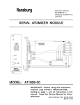
SERVICE MANUAL
LN-9245-00.6
(Replaces LN-9245-00.5)
February - 2008
AIR HEA
TER ASSEMBL
Y
HEATER
ASSEMBLY
MODEL: A1
1065-05
A11065-05
IMPOR
TANT
IMPORT
ANT:: Before using this equipment,
carefully read SAFETY PRECAUTIONS,
starting on page 1, and all instructions in this
manual. Keep this Service Manual for future
reference.
Service Manual Price: €15.00
15.00 (Euro)
$20.00 (U.S.)
N O T E : This manual has been changed from revision LN-9245-00.5 to revision LN-9245-00.6
Reasons for this change are noted under “Manual Change Summary” inside the back
cover of this manual.
LN-9245-00.6
Air Heater Assembly - Contents
CONTENTS
PAGE
SAFETY:
1-4
SAFETY PRECAUTIONS............................................................................................................ 1
HAZARDS / SAFEGUARDS........................................................................................................ 2-4
INTRODUCTION:
5-6
GENERAL DESCRIPTION.......................................................................................................... 5
FEATURES AND BENEFITS...................................................................................................... 5
SPECIFICATIONS....................................................................................................................... 6
INSTALLATION:
7-12
LOCATION...................................................................................................................................
INPUT POWER............................................................................................................................
PNEUMATIC CONNECTIONS...................................................................................................
INSTALLATION OPTIONS..........................................................................................................
FRONT PANEL DISPLAY AND FUNCTIONS...........................................................................
7
7
7-8
8-9
10-11
OPERATION:
13-16
PRINCIPLES OF OPERATION................................................................................................... 13
WIRING DIAGRAM SCHEMATIC............................................................................................... 14
POWER AND CONTROL WIRING DIAGRAM.......................................................................... 15
START-UP.................................................................................................................................... 16
MAINTENANCE:
17-18
HEATER REMOVAL.................................................................................................................... 17
TROUBLESHOOTING GUIDE.................................................................................................... 18
PARTS IDENTIFICATION:
19-20
A110065-05 AIR HEATER ASSEMBLY / PARTS LIST.............................................................. 19-20
ACCESSORIES........................................................................................................................... 20
WARRANTY POLICIES:
21
LIMITED WARRANTY..................................................................................................................21
LN-9245-00.6
Air Heater Assembly - Safety
SAFETY
SAFETY PRECAUTIONS
Before operating, maintaining or servicing any
ITW Ransburg electrostatic coating system, read
and understand all of the technical and safety
literature for your ITW Ransburg products. This
manual contains information that is important for
you to know and understand. This information
relates to USER SAFETY and PREVENTING
EQUIPMENT PROBLEMS. To help you recognize
this information, we use the following symbols.
Please pay particular attention to these sections.
A WARNING! states information to alert you
to a situation that might cause serious injury
if instructions are not followed.
A CAUTION! states information that tells
how to prevent damage to equipment or how
to avoid a situation that might cause minor
injury.
A NOTE is information relevant to the
procedure in progress.
While this manual lists standard specifications
and service procedures, some minor deviations
may be found between this literature and your
equipment. Differences in local codes and plant
requirements, material delivery requirements, etc.,
make such variations inevitable. Compare this
manual with your system installation drawings
and appropriate ITW Ransburg equipment
manuals to reconcile such differences.
!
WARNING
The user MUST read and be familiar
with the Safety Section in this manual and
the ITW Ransburg safety literature therein
identified.
>
> This manual MUST be read and thoroughly understood by ALL personnel who
operate, clean or maintain this equipment!
Special care should be taken to ensure that
the WARNINGS and safety requirements
for operating and servicing the equipment
are followed. The user should be aware of
and adhere to ALL local building and fire
codes and ordinances as well as NFPA33 SAFETY STANDARD, prior to
installing, operating, and/or servicing this
equipment.
!
WARNING
> The hazards shown on the following
page may occur during the normal use of
this equipment. Please read the hazard
chart beginning on page 2.
Careful study and continued use of this manual will
provide a better understanding of the equipment
and process, resulting in more efficient operation,
longer trouble-free service and faster, easier
troubleshooting. If you do not have the manuals
and safety literature for your Ransburg system,
contact your local ITW Ransburg representative
or ITW Ransburg.
1
LN-9245-00.6
Air Heater Assembly - Safety
AREA
HAZARD
SAFEGUARDS
Tells where hazards
Tells what the hazard is.
Tells how to avoid the hazard.
Fire Hazard
Fire extinguishing equipment must be present in the
spray area and tested periodically.
may occur.
Spray Area
Improper or inadequate operation
and maintenance procedures will Spray areas must be kept clean to prevent the
cause a fire hazard.
accumulation of combustible residues.
Protection against inadvertent
arcing that is capable of causing
fire or explosion is lost if any
safety interlocks are disabled
during operation. Frequent power
supply shutdown indicates a
problem in the system requiring
correction.
Smoking must never be allowed in the spray area.
The high voltage supplied to the atomizer must be
turned off prior to cleaning, flushing or maintenance.
When using solvents for cleaning:
Those used for equipment flushing should have flash
points equal to or higher than those of the coating
material.
Those used for general cleaning must have flash
points above 100oF (37.8oC).
Spray booth ventilation must be kept at the rates
required by NFPA-33, OSHA, and local codes. In
addition, ventilation must be maintained during
cleaning operations using flammable or combustible
solvents.
Electrostatic arcing must be prevented.
Test only in areas free of combustible material.
Testing may require high voltage to be on, but only as
instructed.
Non-factory replacement parts or unauthorized
equipment modifications may cause fire or injury.
If used, the key switch bypass is intended for use only
during setup operations. Production should never be
done with safety interlocks disabled.
Never use equipment intended for use in waterborne
installations to spray solvent based materials.
The paint process and equipment should be set up
and operated in accordance with NFPA-33, NEC, and
OSHA requirements.
LN-9245-00.6
2
Air Heater Assembly - Safety
AREA
HAZARD
SAFEGUARDS
Tells where hazards
Tells what the hazard is.
Tells how to avoid the hazard.
may occur.
General Use and
Maintenance
Improper operation or maintenance Personnel must be given training in accordance with
may create a hazard.
the requirements of NFPA-33.
Personnel must be properly trained Instructions and safety precautions must be read and
in the use of this equipment.
understood prior to using this equipment.
Comply with appropriate local, state, and national
codes governing ventilation, fire protection, operation
maintenance, and housekeeping. Reference OSHA,
NFPA-33, and your insurance company requirements.
Electrical
Equipment
High voltage equipment is utilized.
Arcing in areas of flammable or
combustible materials may occur.
Personnel are exposed to high
voltage during operation and
maintenance.
The power supply, optional remote control cabinet,
and all other electrical equipment must be located
outside Class I or II, Division 1 and 2 hazardous
areas. Refer to NFPA-33.
Turn the power supply OFF before working on the
equipment.
Protection against inadvertent
arcing that may cause a fire or Test only in areas free of flammable or combustible
explosion is lost if safety circuits material.
are disabled during operation.
Testing may require high voltage to be on, but only
Frequent power supply shut-down as instructed.
indicates a problem in the system
Production should never be done with the safety
which requires correction.
circuits disabled.
An electrical arc can ignite coating
materials and cause a fire or Before turning the high voltage on, make sure no
objects are within the sparking distance.
explosion.
Explosion Hazard / Halogenated hydrocarbon solvents Aluminum is widely used in other spray application
for example: methylene chloride equipment - such as material pumps, regulators,
Incompatible
and 1,1,1,-Trichloroethane are not triggering valves, etc. Halogenated hydrocarbon
Materials
chemically compatible with the
aluminum that might be used in
many system components. The
chemical reaction caused by these
solvents reacting with aluminum
can become violent and lead to an
equipment explosion.
3
solvents must never be used with aluminum
equipment during spraying, flushing, or cleaning.
Read the label or data sheet for the material you
intend to spray. If in doubt as to whether or not a
coating or cleaning material is compatible, contact
your material supplier. Any other type of solvent may
be used with aluminum equipment.
LN-9245-00.6
Air Heater Assembly - Safety
AREA
HAZARD
SAFEGUARDS
Tells where hazards
Tells what the hazard is.
Tells how to avoid the hazard.
may occur.
Toxic Substances Certain material may be harmful if Follow the requirements of the Material Safety Data
inhaled, or if there is contact with Sheet supplied by coating material manufacturer.
the skin.
Adequate exhaust must be provided to keep the air
free of accumulations of toxic materials.
Use a mask or respirator whenever there is a chance
of inhaling sprayed materials. The mask must be
compatible with the material being sprayed and its
concentration. Equipment must be as prescribed by
an industrial hygienist or safety expert, and be
NIOSH approved.
LN-9245-00.6
4
Air Heater Assembly - Introduction
INTRODUCTION
GENERAL DESCRIPTION
In automated finishing applications, the expansion
of pressurized air causes cooling which may
result in condensation on surfaces of electrostatic
applicators. The ITW Ransburg Air Heater
Assembly is designed to reduce or eliminate
condensation that may form in or on the ITW
Ransburg TurboDisk and Rotary Atomizers, or
other pressurized applicators under certain
operating conditions.
• Heats drive-air to optimum temperature Heats as required to keep rotator housing
warm enough to prevent condensation by
maintaining exhaust temperatures above the
dew point.
• The actual heater process setting depends on
applicator fluid flow rate, booth conditions, air
flow, inlet and ambient air temperatures. The
heater should be set as low as possible, sufficient
to maintain the applicator surface temperatures
above the dewpoint of the booth environment.
Ambient temperature and relative humidity in most
installations is hard to maintain. The Air Heater
Assembly is designed to maintain the temperature
of your operating air supply to ensure no moisture
or condensation will occur on/in the applicator or
its feed or exhaust lines. This helps reduce high
voltage faults and rejected parts due to excess
moisture issues.
FEA
TURES AND
FEATURES
BENEFITS
• Heats up quickly and accurately - Allows
system users to ramp up production in a minimum of time.
• Self contained - Small, compact cabinet features plug'n play components making it easy
to fit into existing systems or add into planned
system designs.
• Cabinet is "touch-safe" - Exterior of the
heater is cool to the touch.
• Precision control - Provides users with accurate temperature feedback via audible and
visual displays and alarms.
5
LN-9245-00.6
Air Heater Assembly - Introduction
SPECIFICA
TIONS
SPECIFICATIONS
Environmental / Physical
Mechanical
Dimensions:
Air Supply
Pressure:
16.5-inch H X 10.31-inch W X 5.5-inch D
41.91 cm H X 26.18 cm W X 13.97 cm D
Weight:
23 lbs./10.43 kilograms
Air Inlet & Outlet:
1/2-inch NPT Pipe Thread
Air Flow:
150 psi (1034 kPa)
maximum
1 SCFM (141.6 SLPM)
minimum
60 SCFM maximum
(1699.0 Liter/minimum)
Electrical
Filtration:
Input/Dual Voltage: 120/240 VAC
+ 10%/15 amps/50-60 hertz
Single Phase
(J1 / J2 jumpers prewired @
240 VAC)
Air Temperature
Output Range:
50 micron
(Additional filtration may be
required depending on
applicator used. Refer to
an "Applicator Manual" for
required filtration.)
50°F to 150°F
(10°C to 66°C)
Mounting Location: Non-hazardous location
Air Flow and Pressure Drop
Comparisons
A11065-05 HEATER
PRESSURE DROP @
85 PSI INLET FLOWING
PRESSURE DROP-PSIG
5
4
3
2
1
0
0
10
20
30
40
50
60
70
AIR FLOW-SCFM
LN-9245-00.6
6
Air Heater Assembly - Installation
INST
ALLA
TION
INSTALLA
ALLATION
LOCA
TION
LOCATION
!
WARNING
> The air heater MUST be located
outside of any hazardous area(s) as
close to applicator as possible. (See
NFPA-33.)
> This manual must be read and thoroughly understood by ALL personnel who
operate, clean, or maintain this equipment.
Special care should be taken to ensure
that the WARNINGS and requirements
for operating and servicing are safely
followed.
Install the air heater near the applicator, but in an
area outside of the hazardous location. The unit
should be located so that it is not exposed to water,
paints or solvents, and high temperatures. (The
ambient temperature should not exceed 120°F.)
!
CAUTION
> Do not locate the unit near or adjacent
to heat producing equipment such as
oven, high wattage lamps, steam pipes,
etc.
INPUT POWER
Input supply voltage connection should be made
from a fused disconnect. Route the input power
wires through the side of the cabinet. Generally,
conduit should be used for the input power.
(Always comply with national and local electrical
codes.)
PNEUMA
TIC
PNEUMATIC
CONNECTIONS
Use appropriate size piping to connect the air
heater to a filtered inlet source. The air heater
compressed air input is at the bottom of the unit
and is identified as "IN". Connect the heated air
output located at the top of the unit identified as "hot
outlet pipe" to the coating applicator(s) using 1/2inch OD, nylon 11/12-inch tubing, with proper
pressure rating.
A secondary sensing air supply must be connected
to the pressure switch [8] through 1/4-inch OD
tube fitting [29].
If the unit is being wired directly to the PLC
electrical connections, the pressure switch must
be by-passed. (Refer to "Figure 1: Installation
Options" for assistance.)
!
!
WARNING
> The air heater cabinet must be properly connected to earth ground.
7
WARNING
> All hardware and tubing used between
the air heater and applicator must have
proper working pressure (150 psig) and
temperature (150°F) ratings.
LN-9245-00.6
Air Heater Assembly - Installation
NOTE
> Recommended air filtration for the air
heater is 50 micron and must be free of
oil. Additional filtration may be required
depending on applicator used. (Refer to
Applicator manual for required filtration.)
!
WARNING
DO NOT operate air heater without a
minimum of 1 SCFM of air flow through
the unit.
>
This electrical circuit must be connected using a
minimum 1 amp dry contact relay (such as PLC
contact). This can be completed by the following:
1. Remove the present wire from TB8-1.
2. Using a wire nut, connect the wire removed in
step 1 to a longer wire and route to one side of the
remote contact.
3. Run a wire from the other side of the remote
contact back to TB8-1.
4. Add pressure switch changes, A1.
When the remote contact is closed, the air heater
will turn on.
INST
ALLA
TION OPTIONS
INSTALLA
ALLATION
(See Figure 1)
Heater Pressure Switch Interlock Options for
Activation:
1. Pilot from one of the following items which
corresponds and signals air is flowing:
a. Volume booster - requires a minimum of 1
psig.
b. PLC pneumatic output - requires a minimum
of 1 psig.
c. Air regulator - requires a minimum of 1 psig.
!
CAUTION
> Never activate heater without air flow.
2. Directly from a remote electrical control (such
as a turbine speed control or PLC). This contact
must correspond and signal that air is flowing
through the heater.
LN-9245-00.6
8
Air Heater Assembly - Installation
Figure 1:
9
Installation Options
LN-9245-00.6
Air Heater Assembly - Installation
!
CAUTION
> Air filters must be located before the
air heater. Heated air may damage air
filters.
> The use of an in-line lubricator before
the air heater is NOT recommended. Oil
laden air passing across the heating
elements results in burnt contaminates
which will accumulate and plug applicator
ports. This action may cause premature
atomizer turbine failure.
> It is the user's responsibility to
ensure clean air at all times. Failures resulting from contaminated air
will not be covered under warranty.
FRONT P
ANEL DISPLA
Y AND FUNCTIONS
PANEL
DISPLAY
FUJI MICRO CONTROLLER "X", MODEL PXG4
LN-9245-00.6
10
Air Heater Assembly - Installation
OPERA
TION P
AR
TS
OPERATION
PAR
ARTS
USER Key
Key
Press this key in monitoring mode display or
setup mode display returns you to the PV/SV
display. Pressing this key on the PV/SV display
allows you to set the function for uTey under the
system menu (5Y5 Ch 7). (The factory set
function for this key is switching between auto
and manual.)
Pressing once will increase the setting value by
one. Holding down the button will continue to
increase the value. It changes SV on the PV/
SV display. It is also used to move between
items in channel screen display and parameter
screen display.
SEL Key
Pressing once will decrease the setting value
by one. Holding down the button will continue to
decrease the value. It changes SV on the PV/
SV display. It is also used to move between
items in channel screen display and parameter
screen display.
Key
Switches the PV/SV display to the monitoring
mode display or setup mode display. Switches to
setup mode when parameter display and this key
functions as the select key when changing
parameters. Holding this key down in channel
display or parameter display returns you to the
PV/SV display. Pressing this key at PV/SV
display in manual mode, manual output value is
shown in the lower display.
DISPLA
Y
DISPLAY
SV Display
Display
C1/C2 Lamp
Displays the condition of the control output. Lights
ON at 100% output and goes out at 0% output. For
values between 0% and 100%, the output is
indicated by the length of time the lamp flickers.
When acting as a valve control, the C1 lamp will
light with OPEN output, and the CS lamp will flicker
with CLOSE output.
DO1/2/3 Lamp
Lights ON when there is digital output is on state
(DO1, DO2, DO3). The lamp flickers when delay
behavior is on.
PV Display
Displays the set value (SV). Also can display the
output value during manual mode. Displays the
parameter setting value when setting parameters.
Displays (rEN) during remote SV operation and
5oFR and set value alternately during soft start.
SV Lamp
Lights when displaying the set value (SV). Goes
out when displaying the manual output value. The
lamp flickers while performing ramp soak or lamp
SV operations.
MAN/AT/SELF Lamp
Normally lights up during manual mode and blinks
during auto-tuning or self-tuning.
Displays the measurement value (PV). Displays
the name of the parameter when setting parameters.
NOTE
> Expect alarm light to flash when auto
tuning.
11
LN-9245-00.6
Air Heater Assembly - Installation
NOTES
LN-9245-00.6
12
Air Heater Assembly - Operation
OPERA
TION
OPERATION
PRINCIPLES OF
OPERA
TION
OPERATION
NOTES
The ITW Air Heater system is shipped as 230V/
1 phase 50/60 Hz operation but can be converted
with simple jumper changes to 115 volt operation.
Heater and controls are contained in a single,
steel NEMA Type 12 enclosure vented to the
atmosphere through access ports for compressed
air delivery.
Three LED indicator lights indicate the status of
the system. Green indicates a "power on"
condition. Red indicates an "alarm condition"
resulting in shutdown of power to the heater.
Amber indicates "insufficient air flow" for safe
operation. The red or amber light remains steady
when ON or can be jumper selected to flash when
ON. In addition, an audible warning option is also
jumper selectable to sound in intermittent warning
when either the red or the amber light is lit.
If an alarm condition occurs such as high
temperature or insufficient air flow, the power to
the heater is interrupted by the safety contactor.
When the alarm condition is removed by the
heater cooling off or the airflow increasing, the
heater will be energized and operate until the
system is turned off or the next alarm condition
occurs.
The heart of the control process is the temperature
controller. Upon startup, or immediately following
the acknowledgement of any alarm condition, the
controller's PID programming provides a fast,
smooth approach to the final temperature setpoint. The PID parameter is set per "Auto-Tuning
Procedure" (see "Controller" manual for "AutoTuning Procedure and all detailed controller
functions").
No cooling is required for the system. Air flow of
at least one (1) SCFM (28.3 SLPM) will satisfy
heater needs.
13
LN-9245-00.6
Air Heater Assembly - Operation
Figure 2:
LN-9245-00.6
Wiring Diagram Schematic
14
Air Heater Assembly - Operation
Figure 3:
15
Power and Control Wiring Diagram
LN-9245-00.6
Air Heater Assembly - Operation
NOTES
ST
AR
T-UP
STAR
ART
1. Apply main power to unit.
2. Turn on and set air at a minimum of 1 SCFM
with a pneumatic pilot signal to the pressure switch
of at least 1 psig.
3. Adjust temperature to desired setting using
the key pad on face panel (maximum setting is
150°F).
NOTE
> Heating the drive-air to between 120°F
and 140°F will usually keep the rotator
housing warm enough to prevent condensation. Use ONLY enough heat to prevent moisture buildup!
4. The unit is now ready for normal operation.
!
CAUTION
> When turning the air heater off, first
remove power and allow the unit to cool
prior to turning off air flow. Failure to do
so may create excessive heat in the
heating element and may cause permanent damage or reduced service life of
heating element.
LN-9245-00.6
16
Air Heater Assembly - Maintenance
MAINTENANCE
HEA
TER REMOV
AL
HEATER
REMOVAL
NOTES
When removing the heater from the system, assure
the following:
• The air supply is off and locked out.
• Main supply power is off and locked out.
• The heating element section, attached fittings,
and tubing are cool enough to touch.
17
LN-9245-00.6
Air Heater Assembly - Maintenance
TROUBLESHOOTING GUIDE
General Problem
Possible Causes
Corrective Action
No Heat Output
1. Power to unit not On
1. Turn Power On.
2. Blown fuse(s) in temperature controller
2. Replace fuse(s) with same type and determine
cause.
3. Air not turned On to unit or
pressure switch
3. Turn air On.
4. Air pressure too low at
pressure switch
4. Increase air pressure signal to the pressure
switch.
5. High limit thermostat switch
off
5. Manually reset switch and investigate reason
for switch turning off.
LN-9245-00.6
18
Air Heater Assembly - Parts Identification
PAR
TS IDENTIFICA
TION
ARTS
IDENTIFICATION
Figure 4:
19
A11065-05 Air Heater Assembly
LN-9245-00.6
Air Heater Assembly - Parts Identification
A1
1065-05 AIR HEA
TER ASSEMBL
Y - P
AR
TS LIST
A11065-05
HEATER
ASSEMBLY
PAR
ARTS
(Figure 4)
Item #
1
2
3
4
5
6
7
8
9
10
11
12
13
14
15
16
17
18
19
20
21
22
23
24
25
26
27
28
29
30
Part #
Description
A11028-00
A11027-00
A11021-00
A11019-00
A11022-00
A11738-00
A11024-00
77235-02
A11026-00
A11005-00
SSH-7739
SSW-8230
5307-01
TRM-35-038
A10996-00
A10997-00
---LSF10072-00
LSF10065-00
3364-04
A11064-00
78167-00
TRC-35-103
7715-00
A11065-11
LSF10065-00
ASI-4004
LN-9245-00
LSF10002
A11737-00
Cool Touch In-Line Air Heater
Thermocouple (Air Heater)
PC Board Assembly (TC0002 - Air Heater)
PC Board Assembly (TC0003 - Air Heater)
Fuse, 15A, CER, ABC (Air Heater)
Temperature Controller (Air Heater)
DPDT Switch (Air Heater)
Pressure Switch (Air Heater)
Relay, Solid State (Air Heater)
Enclosure (Air Heater)
Sheet Metal Plug
PLC Outlet Fitting
Conduit Nut
Ground Label
Decal, Heat Cover
Label, Set (Air Heater)
---Male Elbow, 1/2" OD Tube X 1/2" NPT
Connector, Male
Tee, Pipe 1/2" NPT
Coupling, Pipe 1/2" NPT Stainless Steel
SAE 45° Male Connector, Air Inlet
Serial Tag
Serial No. Label
Purchased Air Heater
1/2" OD Tube Connector, Air Inlet
Temperature Conversion Chart
Manual, Air Heater Assembly
Fitting, 1/4" T X 1/8" NPT, Bulkhead
High Limit Thermostat, Manual Reset
Qty
1
1
1
1
2
1
1
1
1
1
1
1
1
1
1
1
-1
1
1
1
1
1
1
1
1
1
1
1
1
ACCESSORIES
Part #
A12060-00
LN-9245-00.6
Description
PLC Kit (Optional)
20
Air Heater Assembly - Warranty Policies
WARRANTY POLICIES
LIMITED W
ARRANTY
WARRANTY
ITW Ransburg will replace or repair without charge
any part and/or equipment that falls within the
specified time (see below) because of faulty
workmanship or material, provided that the
equipment has been used and maintained in
accordance with ITW Ransburg's written safety
and operating instructions, and has been used
under normal operating conditions. Normal wear
items are excluded.
THE USE OF OTHER THAN ITW RANSBURG APPROVED PARTS, VOID ALL
WARRANTIES.
SPARE PARTS: One hundred and eighty (180)
days from date of purchase, except for rebuilt
parts (any part number ending in "R") for which the
warranty period is ninety (90) days.
EQUIPMENT: When purchased as a complete
unit, (i.e., guns, power supplies, control units,
etc.), is one (1) year from date of purchase.
WRAPPING THE GUN IN PLASTIC WILL
VOID THIS WARRANTY.
21
ITW RANSBURG'S ONLY OBLIGATION
UNDER THIS WARRANTY IS TO REPLACE
PARTS THAT HAVE FAILED BECAUSE
OF FAULTY WORKMANSHIP OR MATERIALS. THERE ARE NO IMPLIED WARRANTIES NOR WARRANTIES OF EITHER
MERCHANTABILITY OR FITNESS FOR A
PARTICULAR PURPOSE.
ITW RANSBURG ASSUMES NO LIABILITY FOR
INJURY, DAMAGE TO PROPERTY OR
FOR CONSEQUENTIAL DAMAGES FOR
LOSS OF GOODWILL OR PRODUCTION
OR INCOME, WHICH RESULT FROM USE
OR MISUSE OF THE EQUIPMENT BY
PURCHASER OR OTHERS.
EXCLUSIONS:
If, in ITW Ransburg's opinion the warranty item in
question, or other items damaged by this part was
improperly installed, operated or maintained, ITW
Ransburg will assume no responsibility for repair
or replacement of the item or items. The purchaser,
therefore will assume all responsibility for any cost
of repair or replacement and service related costs
if applicable.
LN-9245-00.6
MANUAL CHANGE SUMMAR
Y
SUMMARY
This manual was published to replace Service
Manual LN-9245-00.5 Air Heaster Assembly,
to make the following changes:
1. Revised "Figure 4 - A11065-05 Air Heater
Assembly" in the "Parts Identification" section.
2. Removed "A11065-05 Air Heater Assembly
Parts List - Item #17 - A11029-00 - Communication
Card" in the "Parts Identification" section.
LN-9245-00.6
Service Manual Price: €15.00
15.00 (Euro)
$20.00 (U.S.)
Manufacturing
1910 North Wayne Street
Angola, Indiana 46703-9100
Telephone: 260/665-8800
Fax: 260/665-8516
Technical/Service Assistance
Automotive Assembly and Tier I
Industrial Systems
Ransburg Guns
www.itwransburg.com
Telephone: 800/626-3565 Fax: 419/470-2040
Telephone: 800/233-3366 Fax: 419/470-2071
Telephone: 800/233-3366 Fax: 419/470-2071
Technical Support Representative will direct you to the appropriate telephone
number for ordering Spare Parts.
© 2008 Illinois Tool Works Inc. All rights reserved.
Models and specifications subject to change without notice.
Form No. LN-9245-00.6
Litho in U.S.A.
02/08