1
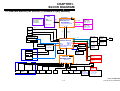
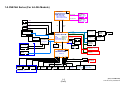
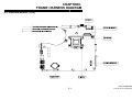
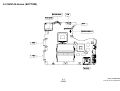
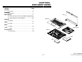
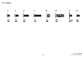
SVE14A Series
SERVICE MANUAL
Ver.1-2012C
Revision History
e
d
i
f
n
o
C
y
n
o
S
9-890-885-01
l
a
i
t
n
Design and specifications are subject to change
without notice.
PERSONAL COMPUTER
Service and Inspection Precautions
Sony, VAIO and CLIE are trademarks or regisSony
regis
teredtrademarks of Sony. Microsoft, Windows,
Windows Media, Outlook, Bookshelf and other
Microsoft products are trademarks or registered
trademarks of Microsoft Corporation in the
United States and other countries. The word
Bluetooth and the Bluetooth logo are trademarks
off Bluetooth
Bl t th SIG,
SIG Inc.
I
AMD the
AMD,
th AMD logo,
l
other
th
AMD product names and combinations thereof
are trademarks of Advanced Micro Devices, Inc.
Intel Inside logo, Pentium, Celeron and Core are
trademarks or registered trademarks of Intel Corporation. Transmeta, the Transmeta logo, Crusoe
Processor, the Crusoe logo and combinations
th
thereof
f are trademarks
t d
k off Transmeta
T
t Corporation
C
ti
in the USA and other countries. Graffi ti, HotSync, PalmModem, and Palm OS are registered
trademarks, and the Hotsync logo and Palm are
trademarks of Palm, Inc. or its subsidiaries. (M)
and Motrola are trademarks of Motrora, Inc. Other
Motrola products and services with (R) mark like
Dragomball are the trademarks of Motrola, Inc.
All other names of systems, products and services
in this manual are trademarks or registered tradeMarks of their respective owners. In this manual,
the (TM) or (R) mark are not specified.
Caution Markings for Lithium/Ion Battery - The
following or similar texts shall be provided on
battery pack of equipment or in both the operating
and the service instructions.
1. Obey precautionary markings and
Instructions
CAUTION: Danger of explosion if battery is
incorrectly replaced. Replace only with the same
or equivalent
i l t type
t
recommended
d d by
b the
th manufacturer. Discard used batteries according to the
manufacturer’s instructions.
Labels and stamps on the cabinet, chassis, and
components identify areas requiring special precautions Be sure to observe these precautions,
cautions.
precautions
as well as all precautions listed in the operating
manual and other associated documents.
CAUTION: The battery pack used in this device
may present a fi re or chemical burn hazard if mistreated. Do not disassemble, heat above 60̓C
(140̓F) or incinerate.
i i
t Dispose
Di
off used
d battery
b tt
promptly. Keep away from children.
2. Use designated parts only
The set’s components possess important safety
characteristics,
h
t i ti
such
h as noncombustibility
b tibilit and
d
the ability to tolerate large voltages. Be sure that
replacement parts possess the same safety characteristics as the originals. Also remember that the
Μ mark, which appears in circuit diagrams and
parts lists, denotes components that have particularly important safety functions; be extra sure to
use only
l th
the d
designated
i
t d components.
t
CAUTION: Changing the back up battery.
• Overcharging, short circuiting, reverse charging, multilation or incineration of the cells must
be avoided to prevent one or more of the following occurrences; release of toxic materials,
release of hydrogen and/or oxygen gas, rise in
surface temperature.
• If a cell has leaked or vented, it should be
replaced immediately while avoiding to touch
it without any protection.
3. Always follow the original design
when mounting parts and routing
Wires
The original layout includes various safety feafea
tures, such as inclusion of insulating materials
(tubes and tape) and the mounting of parts above
the printer board. In addition, internal wiring has
been routed and clamped so as to keep it away
from hot or high-voltage parts. When mounting
parts or routing wires, therefore, be sure to duPli t th
Plicate
the original
i i l llayout.
t
The components identified by mark contain
confidential information.
Strictly follow the instructions whenever the
components repaired and/or replaced.
2
4. Inspect after completing service
After servicing, inspect to make sure that all
screws, components, and wiring have been
returned to their original condition. Also check
the area around the repair
p location to ensure that
repair work has caused no damage, and confirm
safety.
5. When replacing chip
components...
Never reuse components. Also remember that
the negative side of tantalum capacitors is easily
damaged by heat.
6. When handling flexible print
boards...
• The temperature of the soldering-iron tip
should be about 270̓C.
• Do not apply the tip more than three times to
the same pattern.
• Handle patterns with care; never apply force.
Caution: Remember that hard disk drives are
easily damaged by vibration. Always handle
with care. [Sony Confidential]
SVE14A Series (9-890-885-XX)
TABLE OF CON
NTENTS
Section
Title
Page
Section
CHAPTER1. BLOCK DIAGRAM
CHAPTER1
1-1.SVE14A Series (For Ext-Gfx (THAMES-XT(M)) Models)
……………………....................................................... 1-1
1-2.SVE14A Series (For Int-Gfx Models) ........................... 1-2
(to 1
1-2)
2)
CHAPTER2. FRAME HARNESS DIAGRAM
2-1.SVE14A Series (TOP)………………………...……...…. 2-1
2-2.SVE14A Series (BOTTOM)……………………....…..….2-2
(to 2-2)
CHAPTER3 EXPLODED VIEWS
CHAPTER3.
Screws
S-1. Screws……………………………………..…........... 3-2
Palmrest
P-1. Palmrest………………………………….......…...… 3-3
Main Board
M-1. Main Board (For Ext-Gfx (THAMES-XT(M)) Models)
………………........................................................ 3-4
M-2. Main Board (For Int-Gfx Models) ……………….... 3-5
Bottom
B-1. Bottom……………………………………...…...…... 3-6
ODD
D-1. ODD………………………………………….……… 3-7
HDD
H 1 HDD………………………………………….………
H-1.
HDD
3-8
LCD
L-1. LCD…………………………................................... 3-9
Accessories
A-1.
A
1. Accessories………………………….…...…….…… 3
3-10
10
(to 3-10)
Title
Page
CHAPTER4.OTHERS
4-1. Replacing the CPU ……………………………………..….. 4-1
4-2. Holding Method of Motherboard……………...……..……. 4-2
4-3. Handing and Holding Method of LCD…………….......….. 4-3
(to 4-3)
x History of the changes is shown as the “Revision
Revision
History” at the end of this data.
3
[Sony Confidential]
SVE14A Series (9-890-885-XX)
CHA
APTER1.
BLOCK DIA
AGRAM
1-1.SVE14A Series (For Ext-Gfx (THAMES-XT(M)) Mo
odels)
GFX
DDR3 VRAM
AMD
Thames-XT
VRAM 512MB/1GB/2GB
64Mx16bitx4pcs
64Mx16bitx8pcs
128Mx16bitx8pcs
Processor
PECI
(IVB) Dual/Quad Core
(SNB) Dual Core
PCI-E
Gen2
PCIE X16
Micro-FCPGA-988B
(988-pin rPGA socket)
TDP: Dua/Quad Core(35W)
29mm X 29mm
HDMI
TMDS
LVDS
LVDS
P
HD+(1600x900)
HD(1366x768)
FDI
SO-DIMM 1
1600/1333 MHZ
DDR(III) 204 pin
Reverse type P
1600/1333 MHZ
P
37.5 mm X 37.5 mm
P
DMI X4
Gen2
CRT
CRTP
SO-DIMM 0
1600/1333 MHZ
DDR(III) 204 pin
Reverse type P
1600/1333 MHZ
Camera Module
Camera 0.3M and HD
PCH (PPT)
Panther Point-M
P
Digital Mic
USB2.0
Int. Speaker
1Walt x 2
Realtek
ALC269Q_VA
P
HDA
3
PCIE
3
USB 2.0
PCH SPI
XTAL
Ext. Mic In Jack
P
LPC
Transformer
NETSWAP
NS692412 P
P
2 USB3.0
(USB 2.0x 12)
(USB3.0 x 4)
HM76
SATA 6Gb/s
TDP 4W
SATA
(PCIE x 8)
989 Ball FCBGA (SATA x 6)
SATA 3Gb/s HDD P
25 mm X 25 mm
P
w/ Class D Amp.
P
DB*B(Function)
Ethernet GbE
RTL8111F-CG
3
SATA
ODD P
R5U220
Card Reader
RJ45
P
MS Duo(HG)
SD Card
P
P
Mini-PCIE Card
(BT+WLAN)
(WLAN only)
P
BIOS ROM
64M bit x1
25MHZ
ShareROM P
Headphone Jack
P
PECI
USB 2.0
CONN.X2
(W/ BATT Charger)
USB 3.0 X1
(W/ USB2.0 X1)
P
Nuvoton
NPCE895LA0BX
P
USB 3.0 X1
(W/ USB2.0 X1)
TFBGA-144
DB*A(Switch)
Page 67~69
SPI
PWM/TACH
EC ROM
P
SMBus
GPIO
ALS_LX
PS/2
35001 Bus
G sensor P
LIS331DLHTR
SMBus 2
Status LED
P
PowerButton
&Switch
P
Light sensor
P
P
P
FAN
Lid Switch
K/B backlit
P
BATT ID
BATT CONN
P
K/B
P
Touch PAD
ClickPad
Thermal sensor
G7811P81U
Local Sensor:DDR3
Remote Sensor:GPU
P
1--1
HW Thermal Protection *3
Temp.SW 1:CPU
P
Temp.SW 2:AMBIENT
Temp.SW 3:GPU
[Sony Confidential]
SVE14A Series (9-890-885-XX)
1-2.SVE14A Series (For Int-Gfx Models)
Processor
PECI
(IVB) Dual/Quad Core
(SNB) Dual Core
SO-DIMM 0
1333/1600 MHZ
DDR(III) 204 pin
Reverse type P
1333/1600 MHZ
Micro-FCPGA-988B
(988-pin rPGA socket)
TDP: Dua/Quad Core(35W)
HDMI
SO-DIMM 1
1333/1600 MHZ
DDR(III) 204 pin
Reverse type P
1333/1600 MHZ
P
37.5 mm X 37.5 mm
TMDS
P
LVDS
HD+(1600x900)
HD(1366x768)
LVDS
P
FDI
DMI X4
Gen2
CRT
CRTP
Camera Module
Camera 0.3M and HD
PCH (PPT)
Panther Point-M
P
Digital Mic
HDA
Int. Speaker
1 Walt x 2
P
Realtek
ALC269Q-VA
3
USB2.0
3
USB 2.0
XTAL
P
P
SATA 6Gb/s
SATA 3Gb/s
R5U220
Card Reader
SATA
HDD P
P
MS Duo(HG)
SD Card
P
P
Mini-PCIE Card
(BT+WLAN)
(WLAN only)
SATA
ODD P
P
LPC
BIOS ROM
64M bit x1
25MHZ
(SHBM) P
Headphone Jack
USB3.0 X1 (W/ Batt ChargerX1)
P
(W/ USB2.0 X1)
PECI
Nuvoton
NPCE895LA0BX
USB 2.0
CONN.X2
RJ45
P
USB 3.0
PCH SPI
Ext. Mic In Jack
Transformer
NETSWAP
NS692412
P
w/ Class D Amp.
P
DB*B(Function)Page 55~58
PCIE
2
(USB2.0 x 12)
HM76
(USB3.0 x 4)
TDP 4W
(PCIE x 8)
989 Ball FCBGA
(SATA x 6)
25 mm X 25 mm
Ethernet GbE
RTL8111F-CG
3
P
P
USB3.0 X1
(W/ USB2.0 X1)
TFBGA-144
P
SPI
ALS_LX
SMBus
PWM/TACH
EC ROM
P
GPIO
G sensor
LIS331DLHTR
P
PS/2
35001 Bus
SMBus 2
PowerButton
&Switch
Status LED
Light sensor
P
P
P
FAN
Lid Switch
BATT ID
K/B backlit
P
BATT CONN
P
K/B
Touch PAD
P
(Clickpad)
Thermal sensor
NCT7718W
Local Sensor: DDRIII
P
HW Thermal Protection *2
Temp.SW 1:CPU
Temp.SW 2:AMBIENT
DB*A(Switch)
1--2
(EN
ND)
[Sony Confidential]
SVE14A Series (9-890-885-XX)
CHA
APTER2.
FRAME HARNESS DIA
AGRAM
2-1.SVE14A Series (TOP)
2--1
[Sony Confidential]
SVE14A Series (9-890-885-XX)
2-2.SVE14A Series (BOTTOM)
2--2
(EN
ND)
[Sony Confidential]
SVE14A Series (9-890-885-XX)
CHA
APTER3.
EXPLODED
D VIEWS
Section
Screws
Page
S-1.Screws…………………………………………….… 3-2
Palmrest
P-1.Palmrest………………………………………….… 3-3
LCD
Main Board
M-1. Main Board (For Ext-Gfx (THAMES-XT(M)) Models)
……..................................................................... 3-4
M-2. Main Board (For Int-Gfx Models) ………………... 3
3-5
5
Palmrest
Bottom
ODD
HDD
LCD
B-1.Bottom………………………………………………. 3-6
D-1.ODD……………………………………………….… 3-7
H-1.HDD…………………………………………………. 3-8
Main Board
L-1.LCD………………………..………………………… 3-9
Bottom
Accessories
A-1.Accessories……………………………….…….….. 3-10
ODD
HDD
3--1
[Sony Confidential]
SVE14A Series (9-890-885-XX)
S-1. Screws
3--2
[Sony Confidential]
SVE14A Series (9-890-885-XX)
P-1. Palmrest
3--3
[Sony Confidential]
SVE14A Series (9-890-885-XX)
M-1. Main Board (For Ext-Gfx (THAMES-XT(M)) Models)
3--4
[Sony Confidential]
SVE14A Series (9-890-885-XX)
M-2. Main Board (For Int-Gfx Models)
3--5
[Sony Confidential]
SVE14A Series (9-890-885-XX)
B-1. Bottom
3--6
[Sony Confidential]
SVE14A Series (9-890-885-XX)
D-1. ODD
3--7
[Sony Confidential]
SVE14A Series (9-890-885-XX)
H-1. HDD
3--8
[Sony Confidential]
SVE14A Series (9-890-885-XX)
L-1. LCD
3--9
[Sony Confidential]
SVE14A Series (9-890-885-XX)
A-1. Accessories
2005
P
Power
C
Cord
d
2006
AC Ad
Adapter
t
2006
AC Adapter(Stick Type)
2007
Battery Pack
2008
Carrying Case
2009
Bluetooth Mouse
2010
Keyboard Skin
2011
Carrying Pouch
2012
Cable Clip
3-10
ND)
(EN
[Sony Confidential]
SVE14A Series (9-890-885-XX)
CHA
APTER4.
OTHERS
4-1. Replacing the CPU
1. Removing the CPU
2. Installing the CPU
1. Insert a flat-blade screwdriver into the notch as shown
illustration and rotate it so that the protrusion comes to the
lock release position.
2. Pull the CPU gently upward to lift it out of the CPU socket
1. Align the triangle reference mark of the mark the CPU with that of the CPU
socket and insert all the pins of the CPU to the corresponding holes of the
CPU socket.
2. Insert the flat head (-) screwdriver into the specified position and rotate the
screwdriver to the LOCK position.
1
1
Unlock
2
Lock
Reference marks
2
2
Unlock
Lock
1
4--1
[Sony Confidential]
SVE14A Series (9-890-885-XX)
4-2 Holding Method of Motherboard
1. When operating with both hands, gently hold the middle of Main board edge as show
w.
2. When operating with one-hand, gently hold the middle of Main board edge and keep vertical.
(Level)
(Vertical)
4--2
[Sony Confidential]
SVE14A Series (9-890-885-XX)
4-3 Handing and Holding Method of LCD
1. Handling
g Method of LCD
1) Take LCD Panel out of packing box with
its both sides.
Note not to press the PCB.
2) Holding the opposite side of PCB with
p of shielding
g bag
g
one hand,, take off the tape
with the other hand.
3) Holding one side of LCD Panel with one
hand, take off the shielding
g bag
g with the
other hand.
4) Besides the protector sheet, there is
also another soft film on the surface of
Samsung LCD. The soft film is under the
protector sheet. Remove it carefully with
one tape.
2. Holding Method of LCD
(Front View)
(Rear View)
4--3
(EN
ND)
[Sony Confidential]
SVE14A Series (9-890-885-XX)
SVE14A Series
This manual and the constituent data may not be replicated, copied nor
reprinted in whole or in part without prior written authorization of Sony
Corporation
9-890-885-01
Sony Corporation
21
English
2012CF00-1
© 2012 Sony Corporation
Published by Sony Corporation VAIO & Mobile Business Group
CS & Quality Div. VAIO Global CS Dept.
Revision History
Suffix
Ver.
Date
-01
01
Ver 1
Ver.1
2012 03 26
2012.03.26
Contents
QM No.
First Edition
<Remarks>
515
[Sony Confidential]
SVE14A Series (9-890-885-XX)