1
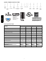
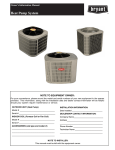
280A EVOLUTIONR EXTREME
VARIABLE SPEED HEAT PUMP
WITH PURONr REFRIGERANT
(2 -- 5 Ton)
Advance Product Data
INDUSTRY LEADING
FEATURES / BENEFITS
Energy Efficiency
S Up to 20.5 SEER/13.0 HSPF
(based on tested combinations)
S Microtube Technologyt refrigeration system
S Indoor air quality accessories available
Sound
S Sound level as low as 58 dBA in low speed .
Comfort
S Variable speed compressor with capacity range from 40--100%
S Air cooled Inverter variable speed drive
—
System requires Evolution Control
(SYSTXBBUID01--D or SYSTXBBUIZ01--D software
version 23 or newer)
Reliability
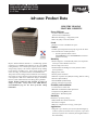
Bryant’s 280A Evolutionr Extreme is a breakthrough product
providing up to 13 HSPF heating efficiency and up to 20.5 SEER
cooling efficiency. The variable speed capacity control results in
strong heating capacity as the outdoor temperature drops resulting
in less reliance on auxiliary heat. Lower speed operation, when
needed in cooling, for enhanced comfort and dehumidification.
This product has been designed and manufactured to meet Energy
Starr criteria for energy efficiency when matched with appropriate
coil components. Refer to the combination ratings in the Product
Data for system combinations that meet Energy Starr guidelines.
NOTE: Ratings contained in this document are subject to
change at any time. Always refer to the AHRI directory
(www.ahridirectory.org) for the most up--to--date ratings
information.
S Puronr refrigerant -- environmentally sound, won’t deplete the
ozone layer and low lifetime service cost.
S Front--seating service valves
S Evolutionr Extreme Intelligence actively monitors critical
system parameters
S High pressure switch
S Suction pressure transducer
S Electronic expansion valve (EXV) for heating, TXV for cooling
S Filter drier (field installed)
S External Muffler (field installed)
S Internal crankcase heater standard
Flexibility and installation:
S
S
S
S
2 control wires to outdoor unit
Minimum and maximum airflow adjustments
Compressor heating RPM control
Hybrid Heatt Dual Fuel capable
Durability
DuraGuardt protection package:
S Solid, Durable sheet metal construction
S Steel louver coil guard
S Baked--on, complete outer coverage, powder paint
Applications
S Long--line -- up to 250 feet (76.2 m) total equivalent length, up
to 200 feet (60.96 m) condenser above evaporator, or up to 80 ft.
(24.38 m) evaporator above condenser (See Longline Guide for
more information.)
MODEL NUMBER NOMENCLATURE
1
N
2
N
3
N
4
A
5
A/N
6
N
7
N
8
N
9
N
10
A/N
11
A/N
12
N
14
A
2
8
0
A
N
V
0
3
6
0
0
0
A
Product
Family
2=HP
Tier
SEER
Major
Series
A=Puron
Voltage
Variations
Open
Open
Open
Series
N= 208 ---230 ---1
or 208/230 ---1
V = Variable
Speed
0=Not
Defined
0=Not
Defined
0=Not
Defined
A=
Original
Series
8=
0 = 20 SEER
Evolution
Series
280A
the environmentally sound refrigerant
Cooling Capacity
Use of the AHRI Certified
TM Mark indicates a
manufacturer’s
participation in the
program For verification
of certification for individual
products, go to
www.ahridirectory.org.
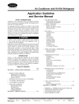
This product has been designed and manufactured to
meet Energy Star® criteria for energy efficiency when
matched with appropriate coil components. However,
proper refrigerant charge and proper air flow are critical
to achieve rated capacity and efficiency. Installation of
this product should follow all manufacturing refrigerant
charging and air flow instructions. Failure to confirm
proper charge and air flow may reduce energy
efficiency and shorten equipment life.
STANDARD FEATURES
FEATURES
Unit Size --- Voltage, Series
024 ---A
036 ---A
048 ---A
060 ---A
Puron Refrigerant
X
X
X
X
Louvered Coil Guard
X
X
X
X
Field Installed Filter Drier / External Muffler
X
X
X
X
Front Seating Service Valves
X
X
X
X
Internal Pressure and Temperature Protection
X
X
X
X
Long Line capability
X
X
X
X
Suction Pressure Transducer
X
X
X
X
High Pressure Switch
X
X
X
X
Crankcase Heater
X
X
X
X
Low ambient cooling down to 0_F capability
with Evolution Control
X
X
X
X
Utility Interface Connections
X
X
X
X
Enhanced Diagnostics with Evolution Control
X
X
X
X
Deluxe Sound Blanket
X
X
X
X
Outdoor Air Temperature Sensor
X
X
X
X
X = Standard
2
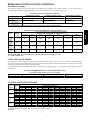
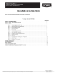
REFRIGERANT PIPING LENGTH LIMITATIONS
Maximum Line Lengths:
The maximum allowable total equivalent length for heat pumps varies depending on the vertical separation. See the tables below for
allowable lengths depending on whether the outdoor unit is on the same level, above or below the outdoor unit.
Maximum Line Lengths for Heat Pump Applications
Units on equal level
MAXIMUM ACTUAL LENGTH
ft (m)
200 (61)
MAXIMUM EQUIVALENT LENGTH{
ft (m)
250 (76.2)
MAXIMUM VERTICAL SEPARATION ft (m)
N/A
200 (61)
250 (76.2)
200 (61)
Outdoor unit ABOVE
indoor unit
Outdoor unit BELOW
indoor unit
See Table ’Maximum Total Equivalent Length: Outdoor Unit BELOW Indoor Unit’
{ Total equivalent length accounts for losses due to elbows or fitting. See the Long Line Guideline for details.
Size
Liquid Line
Diameter
w/ TXV
024
HP with
Puron
036
HP with
Puron
048
HP with
Puron
060
HP with
Puron
HP with Puronr Refrigerant --- Maximum Total Equivalent Length{
Vertical Separation ft (m) Outdoor unit BELOW indoor unit;
21--- 30
31--- 40
41--- 50
51--- 60
61--- 70
(6.4 --- 9.1)
(9.4 --- 12.2)
(12.5 --- 15.2)
(15.5 --- 18.3)
(18.6 --- 21.3)
0--- 20
(0 --- 6.1)
71--- 80
(21.6 --- 24.4)
3/8
250*
250*
250*
250*
250*
250*
250*
3//8
250*
250*
250*
250*
250*
250*
250*
3/8
250*
250*
250*
250*
230
160
--- ---
3/8
250*
225*
190
150
110
--- ---
--- ---
* Maximum actual length not to exceed 200 ft (61 m)
{ Total equivalent length accounts for losses due to elbows or fitting. See the Long Line Guideline for details.
--- --- = outside acceptable range
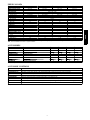
LONG LINE APPLICATIONS
An application is considered Long Line when the refrigerant level in the system requires the use of accessories to maintain acceptable
refrigerant management for systems reliability. Defining a system as long line depends on the liquid line diameter, actual length of the tubing,
and vertical separation between the indoor and outdoor units.
For Heat Pump systems, the chart below shows when an application is considered Long Line. Beyond these lengths, long line accessories
are required:
HP WITH PURONr REFRIGERANT LONG LINE DESCRIPTION ft (m)
Beyond these lengths, long line accessories are required
Liquid Line Size
Units On Same Level
Outdoor Below Indoor
Outdoor Above Indoor
3/8
80 (24.4)
20 (6.1) vertical or 80 (24.4) total
80 (24.4)
Note: See Long Line Guideline for details
COOLING CAPACITY LOSS TABLE
Nominal
Size
(Btuh)
24000
36000
48000
60000
Line OD
(in.)
5/8
3/4
7/8
5/8
3/4
7/8
3/4
7/8
1 1/8
3/4
7/8
1 1/8
25
0.5
0.1
0.0
1.1
0.3
0.0
0.7
0.3
0.0
1.0
0.4
0.0
50
1.2
0.4
0.1
2.4
0.8
0.3
1.6
0.7
0.1
2.3
1.0
0.1
75
1.8
0.6
0.3
3.7
1.3
0.5
2.4
1.1
0.2
3.5
1.7
0.3
80
1.9
0.7
0.3
4.0
1.4
0.6
2.6
1.2
0.3
3.8
1.8
0.4
280A Cooling Capacity Loss (%)
Total Equivalent Line Length (ft)
100
125
150
2.4
3.0
3.7
0.8
1.1
1.3
0.4
0.5
0.6
5.0
6.3
7.7
1.8
2.3
2.8
0.8
1.0
1.3
3.2
4.1
4.9
1.6
2.0
2.4
0.4
0.5
0.6
4.8
6.0
7.3
2.3
2.9
3.5
0.5
0.7
0.8
Rating Line Size in Bold
TE Length Greater than 80 ft requires Long Line Accessory Liquid Line Solenoid
3
175
4.3
1.5
0.7
9.0
3.2
1.5
5.7
2.8
0.7
8.5
4.2
1.0
200
4.9
1.8
0.8
10.3
3.7
1.8
6.5
3.2
0.8
9.8
4.8
1.2
225
5.5
2.0
1.0
11.6
4.2
2.0
7.4
3.6
0.9
11.0
5.4
1.4
250
6.2
2.3
1.1
12.9
4.7
2.3
8.2
4.1
1.0
12.3
6.0
1.5
280A
Maximum Total Equivalent Length{ -- Outdoor Unit BELOW Indoor Unit
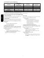
EQUIPMENT SIZING GUIDELINES
If primary load is cooling, size the same as any other air conditioning system. If primary load is heating, use the chart below for maximum
size for heating.
MAXIMUM RECOMMENDED EQUIPMENT SIZE -- HEATING
COOLING LOAD (tons)
MAXIMUM RECOMMENDED EQUIPMENT SIZE FOR HEATING*
2
2.5
36
36
3
3.5
48
60
4
60
5
60
* Make sure duct work is capable of delivering required airflow . Make sure combination rating exists for desired combination.
280A
MIN/MAX AIRFLOW TABLES
The indoor airflow delivered by this system varies significantly
based on outdoor temperature, indoor unit combination, and
system demand. The airflows on these tables are for duct design
considerations. Duct systems capable of these ranges will ensure
the system will deliver full capacity at all outdoor temperatures.
Minimum and maximum airflows can be adjusted from these
numbers in the Evolution Control Heat Pump Setup screen.
Cooling --- Comfort Mode
Max Capacity
Min Capacity
Minimum Cooling
(Dehum or Zoning)
24
726
651
398
36
1168
651
398
48
1394
1186
693
60
1650
1186
693
Size
Cooling --- Efficiency Mode
Size
Max Capacity
Min Capacity
24
949
830
36
1334
830
48
1593
1355
60
1885
1355
Heating --- Comfort Mode
Size
Max Capacity
Min Capacity
24
698
440
36
1140
451
48
1354
751
60
1354
751
Heating --- Efficiency Mode
Size
Max Capacity
Min Capacity
24
900
750
36
1350
750
48
1600
890
60
1750
901
4
UNIT SIZE SERIES
024--- A
036--- A
048--- A
060--- A
Operating Weight lb (kg)
324 (147)
324 (147)
334 (152)
334 (152)
Shipping Weight lb (kg)
367 (167)
367 (167)
375 (170)
375 (170)
Compressor Type
Variable Speed Scroll
REFRIGERANT
Puron® (R---410A)
Control
TXV (Puron® Hard Shutoff)
Charge lb (kg)
13.00 (5.90)
13.00 (5.90)
13.30 (6.03)
13.30 (6.03)
Outdoor Htg Exp. Device
EXV
EXV
EXV
EXV
COND FAN
Forward Swept Propeller Type, Direct Drive
Air Discharge
Vertical
Air Qty (CFM)
2700
4269
4350
5000
Motor HP
1/3
1/3
1/3
1/3
Motor RPM
500 ---900
500 ---900
500 ---900
500 ---900
COND COIL
Face Area (Sq ft)
30.25
30.25
30.25
30.25
Fins per In.
20
20
20
20
Rows
2
2
2
2
Circuits
8
8
9
9
VALVE CONNECT. (In. ID)
Vapor
7/8
7/8
7/8
7/8
Liquid
3/8
REFRIGERANT TUBES (In. OD)
Rated Vapor*
7/8
7/8
1 ---1/8
1 ---1/8
Max Liquid Line
3/8
* Units are rated with 25 ft (7.6 m) of lineset length. See Vapor Line Sizing and Cooling Capacity Loss table when using other sizes and lengths of lineset.
Note: See unit Installation Instruction for proper installation.
ACCESSORIES
KIT NUMBER
KHAEM0101EMI
KHALS0401LLS
KHASS0606MPK*
KSASF0101AAA
KSATX0301PUR
KSATX0401PUR
KSATX0501PUR
STANDARD
KIT NAME
ELECTRO --- MAGNETIC INTERFERENCE KIT
SOLENOID VALVE
SNOW STAND
SUPPORT FEET
TXV
TXV
TXV
CRANKCASE HEATER
024---A
X
X
X
X
X
036---A
X
X
X
X
X
048---A
X
X
X
X
060---A
X
X
X
X
X
S
S
S
X
S
x = Accessory S = Standard * Available from RCD
ACCESSORY CONTROLS
CONTROL
DESCRIPTION
SYSTXBBUID01--- D*
Evolution Control Deluxe 7 ---Day Programmable (Wall ---mounted system control.)
SYSTXBBUIZ01--- D*
Evolution Control Deluxe Zoning 7 ---Day Programmable (Wall ---mounted control for a multi---zone system.)
SYSTXBB4ZC01
Evolution 4 ---Zone Damper Control Module (Wall ---mounted control for a four ---zone system.)
SYSTXBBSMS01
Evolution Smart Sensor (Optional wall control used to monitor temperature and/or fan control in an individual zone.)
SYSTXBBRRS01
Evolution Remote Room Sensor (Monitors temperature in an individual zone.)
SYSTXBBRWF01
Evolution System Access Module (Hardware for wireless access and control via phone or internet.)
SYSTXBBNIM01
Evolution Network Interface Module (Connects Heat Recovery and Energy Recovery Ventilators on non ---zoning applications.)
SYSTXBBLBPU01--- C
Decorative Back Plate for Evolution Control (Decorative wall plate.)
* Requires software version 23 or newer
5
280A
PHYSICAL DATA
ACCESSORY USAGE GUIDELINE
ACCESSORY
Crankcase Heater
Evaporator Freeze Protection
Liquid --- Line Solenoid Valve
Low--- Ambient Control
Puron Refrigerant Balance Port Hard --ShutOff TXV
Support Feet
Winter Start Control
REQUIRED FOR
LOW --- AMBIENT COOLING APPLICATIONS
(Below 55°F/12.8_C)
REQUIRED FOR LONG LINE APPLICATIONS*
(Over 80 ft/24.38 m)
REQUIRED FOR SEA COAST
APPLICATIONS (Within 2
miles/3.22 km)
Standard
Standard with Evolution Control
No
Standard with Evolution Control
Standard
No
Standard
No
No
No
Yes{
Yes{
Yes{
Recommended
Standard with Evolution Control
No
No
Recommended
No
No
Yes
* For tubing set lengths between 80 and 200 ft. (24.38 and 60.96 m) horizontal or 20 ft. (6.10 m) vertical differential (total equivalent length), refer to the Long
Line Guideline—Air Conditioners and Heat Pumps using Puron® Refrigerant.
{ Required on all indoor units. Standard on all new Greenspeed™ compatible fan coils and furnace coils.
280A
Accessory Description and Usage (Listed Alphabetically)
1. Compressor Start Assist
The inverter drive gently starts the variable speed compressor at all
times. No other start device is compatible with this unit.
2. Crankcase Heater
Compressor motor winding resistance heater which is internal to
compressor to keep the lubricant warm during off cycles. Improves
compressor lubrication on restart and minimizes the chance of
liquid slugging.
Usage:
Used in low ambient cooling applications.
Used in long line applications.
3. Liquid--Line Solenoid Valve (LLS)
An electrically operated shutoff valve which stops and starts
refrigerant liquid flow in response to compressor operation. It is to
be installed at the outdoor unit to control refrigerant off cycle
migration in the heating mode.
Usage Guideline:
An LLS is required in all long line heat pump
applications to control refrigerant off cycle migration in
the heating mode. See Long Line Guideline.
Suggested for all commercial applications.
4. Snow Stand
Coated wire rack which supports unit 18 in. (457.2 mm) above
mounting pad to allow for drainage from unit base.
Usage Guideline:
Suggested in the following applications:
Heat pump installations in heavy snowfall areas.
Heat pump installations in snow drift locations.
Heat pump installations in areas of prolonged
subfreezing temperatures.
All commercial installations.
5. Thermostatic Expansion Valve (TXV) Bi--Flow
A modulating flow--control valve which meters refrigerant liquid
flow rate into the evaporator in response to the superheat of the
refrigerant gas leaving the evaporator.
Usage Guideline:
Accessory required to meet AHRI rating and system
reliability, where indoor not equipped.
Required in all heat pump applications designed with
Puron refrigerant.
6. Electro--Magnetic Interference Kit
Usage Guideline:
May be required to address radio frequency interference
for equipment, such as HAM radios, operating between 6
and 30 mHz.
6
LRA
RLA
FLA
024--- A
24
16.5
2.9
23.5
12
12
52 (15.9)
50 (16.2)
MAX
FUSE*
* or
CKT
BRK
AMPS
30
036--- A
24
16.5
2.9
23.5
12
12
52 (15.9)
50 (16.2)
40
42
27.0
2.9
36.6
8
8
84 (25.6)
80 (24.3)
50
UNIT
SIZE --VOLTAGE,
SERIES
048--- A
OPER VOLTS*
COMPR
FAN
V/PH
MCA
MAX
208 ---230 ---1
253
MIN
197
MIN
WIRE
SIZE{
MIN
WIRE
SIZE{
MAX
LENGTH
ft (m)}
MAX
LENGTH
ft (m)}
60°C
75°C
60°C
75°C
060--- A
42
27.0
2.9
36.6
8
8
84 (25.6)
80 (24.3)
50
* Permissible limits of the voltage range at which the unit will operate satisfactorily
{ If wire is applied at ambient greater than 30_C, consult table 310 ---16 of the NEC (NFPA 70). The ampacity of non ---metallic---sheathed cable (NM),
trade name ROMEX, shall be that of 60_C conditions, per the NEC (NFPA 70) Article 336 ---26. If other than uncoated (no ---plated), 60 or 75_C
insulation, copper wire (solid wire for 10 AWG or smaller, stranded wire for larger than 10 AWG) is used, consult applicable tables of the NEC (NFPA 70).
} Length shown is as measured 1 way along wire path between unit and service panel for voltage drop not to exceed 2%.
** Time ---Delay fuse.
FLA --- Full Load Amps
LRA --- Locked Rotor Amps
MCA --- Minimum Circuit Amps
RLA --- Rated Load Amps
NOTE: Control circuit is 24 ---V on all units and requires external power source. Copper wire must be used from service disconnect to unit.
All motors/compressors contain internal overload protection.
Complies with 2010 requirements of ASHRAE Standards 90.1
SOUND POWER LEVEL (dBA)
Typical Octave Band
Min Speed
Max Speed
Spectrum
Cooling
Cooling
(without tone adjustment)
Freq (Hz)
1800 RPM
3200 RPM
125
62.0
63.0
250
57.0
56.5
500
54.5
57.5
0024--- A
1000
52.0
58.0
2000
47.5
54.0
4000
44.5
48.0
8000
52.5
54.5
Sound Rating (dBA)
58
63
Freq (Hz)
1800 RPM
4500 RPM
125
62.0
64.5
250
57.0
60.5
500
54.5
61.0
0036--- A
1000
52.0
61.0
2000
47.5
56.0
4000
44.5
51.0
8000
52.5
54.5
Sound Rating (dBA)
58
65
Freq (Hz)
1800 RPM
3450 RPM
125
62.0
70.0
250
60.5
67.5
500
56.0
67.0
0048--- A
1000
59.0
63.0
2000
54.0
60.0
4000
52.5
56.0
8000
58.5
58.5
Sound Rating (dBA)
65
70
Freq (Hz)
1800 RPM
4250 RPM
50
62.0
65.0
100
60.5
67.5
200
56.0
67.5
0060--- A
400
59.0
66.5
800
54.0
61.0
1600
52.5
60.5
3150
58.5
59.0
Sound Rating (dBA)
65
72
NOTE: Tested in compliance with AHRI 270 ---2008 but not listed with AHRI.
* 024 & 036 tested at 44_F Outdoor Air Temperature. 048 & 060 tested at 40_F
**Testable RPM limited by outdoor temp. Max unit RPM is 6500 for the 4 ton and 7000 for the 3 and 5 ton.
Unit Size --- Voltage, Series
*Min Speed
Heating
*Max Speed
Heating
1800 RPM
63.0
61.5
58.5
54.5
51.5
48.0
54.0
62
1800 RPM
63.0
61.5
58.5
54.5
51.5
48.0
54.0
62
1800 RPM
66.0
63.0
63.0
58.0
53.5
50.0
57.0
64
1800 RPM
66.0
63.0
63.0
58.0
53.5
50.0
57.0
64
5700 RPM
73.5
63.0
66.0
63.5
64.5
59.5
61.5
71
6850**
67.0
67.5
69.0
67.0
67.0
63.0
61.5
75
6300**
73.5
69.5
73.5
72.0
66.5
65.5
63.0
76
6300**
73.5
69.5
73.5
72.0
66.5
65.5
63.0
76
CHARGING SUBCOOLING (TXV--TYPE EXPANSION DEVICE)
UNIT SIZE --- VOLTAGE, SERIES
024--- A
036--- A
048--- A
060--- A
REQUIRED SUBCOOLING _F (_C) --- See UI
Subcooling recommendation displayed on UI in Charging Mode must be followed
7
280A
ELECTRICAL DATA
8
DIMENSIONS -- ENGLISH
280A
9
DIMENSIONS -- SI
280A
10
0.00
5.00
10.00
15.00
20.00
25.00
30.00
35.00
-10 (-23.3)
0 (-17.8)
10 (-12.2)
30 (-1.1)
40 (4.4)
OUTDOOR TEMPERATURE F (C)
20 (-6.7)
50 (10)
60 (15.6)
70 (21.1)
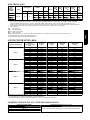
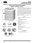
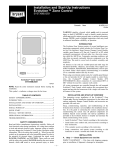
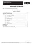
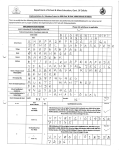
BASED ON INDOOR ENT. AIR AT
70°F(21.1°C )
Maximum Capacies
Minimum Capacies
280ANA024 BALANCE POINT WORK SHEET
(MINIMUM & MAXIMUM HEATING CAPACITIES)
280A BALANCE POINT WORKSHEET
BUILDING HEAT LOSS, UNIT INTEGRATED HEATING CAPACITY, MBTUH
280A
80 (26.7)
0.00
2.9
5.9
8.8
KW
11
BUILDING HEAT LOSS, UNIT INTEGRATED HEATING CAPACITY, MBTUH
0.00
5.00
10.00
15.00
20.00
25.00
30.00
35.00
40.00
45.00
-10 (-23.3)
0 (-17.8)
10 (-12.2)
30 (-1.1)
40 (4.4)
OUTDOOR TEMPERATURE F (C)
20 (-6.7)
280A
60 (15.6)
70 (21.1)
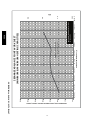
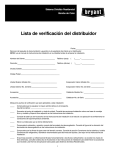
BASED ON INDOOR ENT. AIR AT
70°F(21.1°C )
50 (10)
Maximum Capacies
Minimum Capacies
280ANA036 BALANCE POINT WORKSHEET
(MINIMUM & MAXIMUM HEATING CAPACITIES)
280A BALANCE POINT WORKSHEET CONT.
80 (26.7)
0.0
2.9
5.9
8.8
KW
12
-10 (-23.3)
0 (-17.8)
10 (-12.2)
20 (-6.7)
Minimum Capacies
0.00
10.00
20.00
40 (4.4)
OUTDOOR TEMPERATURE F (C)
30 (-1.1)
Maximum Capacies
50 (10)
BASED ON INDOOR ENT. AIR AT
70°F(21.1°C)
60 (15.6)
70 (21.1)
11.7
40.00
0.0
80 (26.7)
2.9
5.9
8.8
14.8
50.00
30.00
17.6
20.5
60.00
70.00
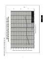
280ANA048 BALANCE POINT WORK SHEET
MINIMUM AND MAXIMUM HEATING CAPACITIES
280A BALANCE POINT WORKSHEET CONT.
BUILDING HEAT LOSS, UNIT INTEGRATED HEATING CAPACITY, MBTUH
280A
KW
13
BUILDING HEAT LOSS, UNIT INTEGRATED HEATING CAPACITY, MBTUH
-10 (-23.3)
0 (-17.8)
10 (-12.2)
20 (-6.7)
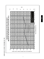
Minimum Capacies
0.00
10.00
40 (4.4)
OUTDOOR TEMPERATURE F (C)
30 (-1.1)
Maximum Capacies
BASED ON INDOOR ENT. AIR AT
70°F(21.1°C)
50 (10)
280A
60 (15.6 )
70 (21.1)
80 (26.7)
0.0
2.9
5.9
20.00
11.7
40.00
8.8
14.8
50.00
30.00
17.6
20.5
60.00
70.00
280ANA060 BALANCE POINT WORK SHEET
MINIMUM AND MAXIMUM HEATING CAPACITIES
280A BALANCE POINT WORKSHEET CONT.
KW
14
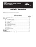
24”
(609.6)
Service
12”
(304.8)
12”
(304.8)
24”
(609.6)
Note: Numbers in ( ) = mm
24”
(609.6)
24”
(609.6)
Service
Wall
6”
(152.4 mm)
24”
(609.6)
Service
Wall
24”
(609.6)
12”
(304.8)
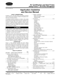
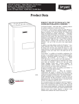
Clearances (various examples)
24”
(609.6)
Service
12”
(304.8)
24”
Service
Wall
6”
(152.4)
IMPORTANT: When installing multiple units in an alcove, roof well, or partially enclosed area, ensure there is adequate ventilation to prevent re--circulation of discharge air.
CLEARANCES
280A
Wall
A07833
GUIDE SPECIFICATIONS
GENERAL
System Description
—
—
—
—
Compressor
Quality Assurance
—
—
—
—
—
—
—
Unit will be rated in accordance with the latest edition of
AHRI Standard 240.
Unit will be certified for capacity and efficiency, and
listed in the latest AHRI directory.
Unit construction will comply with latest edition of
ASHRAE and with NEC.
Unit will be constructed in accordance with UL
standards and will carry the UL label of approval. Unit
will have C--UL approval.
Unit cabinet will be capable of withstanding Federal Test
Method Standard No. 141 (Method 6061) 500--hr salt
spray test.
Air--cooled condenser coils are pressure tested and the
outdoor units are leak tested.
Unit constructed in ISO9001 approved facility.
—
—
—
Condenser Coil
—
—
—
Unit will be shipped as single package only and is stored
and handled per unit manufacturer’s recommendations.
—
Warranty (for inclusion by specifying engineer)
—
U.S. and Canada only.
PRODUCTS
—
Factory--assembled, single--piece, air--cooled heat pump
unit. Contained within the unit enclosure is all factory
wiring, piping, controls, compressor, refrigerant charge
Puronr (R--410A) refrigerant, and special features
required prior to field start--up.
—
Unit Cabinet
—
Unit cabinet will be constructed of galvanized steel,
bonderized, and coated with a powder coat paint.
—
Fans
—
Condenser fan will be direct--drive propeller type,
forward swept blade, discharging air upward.
Refrigeration circuit components will include liquid--line
front--seating shutoff valve with sweat connections,
vapor--line front--seating shutoff valve with sweat
connections, system charge of Puronr (R--410A)
refrigerant, POE compressor oil, accumulator, charge
compensator, electronic expansion valve, and reversing
valve.
Unit will be equipped with high--pressure switch, suction
pressure transducer, and filter drier for Puronr refrigerant
and an electronic expansion valve (EXV) for metering in
heating mode.
Operating Characteristics
Equipment
—
Condenser coil will be air cooled.
Coil will be constructed of aluminum fins mechanically
bonded to copper tubes which are then cleaned,
dehydrated, and sealed.
Refrigeration Components
Delivery, Storage, and Handling
—
Compressor will be hermetically sealed.
Compressor will be mounted on rubber vibration
isolators.
Compressor will be covered with a sound absorbing
blanket.
The capacity of the unit will meet or exceed _____ Btuh
at a suction temperature of _____ _F (_C). The power
consumption at full load will not exceed _____ kW.
Combination of the unit and the evaporator or fan coil
unit will have a total net cooling capacity of _____ Btuh
or greater at conditions of _____ CFM entering air
temperature at the evaporator at _____ _F (_C) wet bulb
and _____ _F (_C) dry bulb, and air entering the unit at
_____ _F (_C).
The system will have a SEER of _____ Btuh/watt or
greater at DOE conditions.
Electrical Requirements
—
—
—
Nominal unit electrical characteristics will be _____ v,
single phase, 60 hz. The unit will be capable of
satisfactory operation within voltage limits of _____ v to
_____ v.
Unit electrical power will be single point connection.
Control circuit will be 24v.
Special Features
—
—
15
Refer to section of this literature identifying accessories
and descriptions for specific features and available
enhancements.
Evolution control with appropriate software version is
required for full featured operation.
280A
Outdoor--mounted, air--cooled, split--system heat pump unit
suitable for ground or rooftop installation. Unit consists of a
hermetic compressor, an air--cooled coil, forward--swept blade
propeller--type condenser fan, and a control box. Unit will
discharge supply air upward as shown on contract drawings. Unit
will be used in a refrigeration circuit to match up to a packaged fan
coil or coil unit.
AIR--COOLED, SPLIT--SYSTEM HEAT PUMP
280ANA
2 TO 5 NOMINAL TONS
Condenser fan motors will be totally enclosed, 1--phase
type with class B insulation and permanently lubricated.
Shafts will be corrosion resistant.
Fan blades will be statically and dynamically balanced.
Condenser fan openings will be equipped with coated
steel wire safety guards.
SYSTEM DESIGN SUMMARY
1.
2.
3.
4.
5.
6.
7.
8.
9.
280A
10.
11.
Intended for outdoor installation with free air inlet and outlet. Outdoor fan external static pressure available is less than 0.01--in. wc.
This product is qualified for low ambient cooling operation (below 55_F / 12.8_C) with an Evolution User Interface ONLY.
The maximum outdoor operating ambient in cooling mode is 125_F (51.67_C).
Minimum outdoor operating air temperature for heating mode is –15_F (–26.1_C).
Maximum outdoor operating air temperature for heating mode is 66_F (18.9_C).
For reliable operation, unit should be level in all horizontal planes.
For interconnecting refrigerant tube lengths greater than 80 ft (23.4 m) and/or elevation differences between indoor and outdoor units
greater than 20 ft (6.1 m), consult Residential Piping and Longline Guideline and Service Manual available from equipment distributor.
If any refrigerant tubing is buried, provide a 6 in. (152.4 mm) vertical rise to the valve connections at the unit. Refrigerant tubing
lengths up to 36 in. (914.4 mm) may be buried without further consideration. Do not bury refrigerant lines longer than 36 in. (914.4
mm).
Use only copper wire for electric connection at unit. Aluminum and clad aluminum are not acceptable for the type of connector
provided.
Do not apply capillary tube indoor coils to these units.
Factory--supplied filter drier must be installed.
EBryant Heating & Cooling Systems 7310 W. Morris St. Indianapolis, IN 46231
Printed in U.S.A.
Edition Date: 01/12
Manufacturer reserves the right to discontinue, or change at any time, specifications or designs without notice and without incurring obligations.
16
Catalog No. APD280A ---01
Replaces: New