1
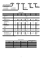
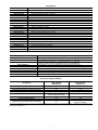
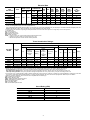
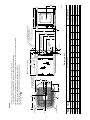
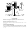
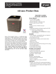
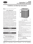
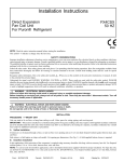
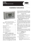
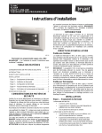
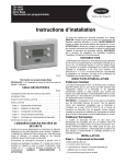
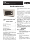
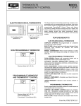
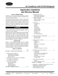
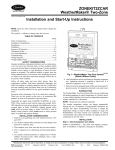
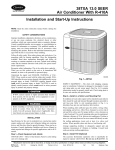
38YXA
13 SEER Split-System
Heat Pump with R-410A
Visit www.carrier.com
Preliminary Product Fact Sheet
Data for Preliminary Use Only
The model 38YXA Heat Pump uses the environmentally-safe refrigerant R-410A. The unit is available in nominal sizes 024 through 060.
The unit features a copper tube, enhanced aluminum fin coil for a
compact, low-profile appearance with vertical air discharge.
This unit also features Carrier’s Silencer System which allows
outstanding performance with reduced sound levels. The Silencer
System consists of a compressor sound hood and vibration isolation
plate to muffle compressor noise, a discharge muffler to minimize low
frequency sound and pressure pulsation generated by compressor
discharge gas, an energy-efficient fan and fan motor to move air more
efficiently, and the InViroFlow™ design for an improved airflow
pattern which requires less energy.
All units contain scroll compressors specially designed for use with
R-410A.
•
•
•
•
•
•
•
•
•
•
•
•
•
•
•
•
FEATURES
SEER up to 14.5 and HSPF up to 8.5 with specified Carrier
equipment
Silencer System
Environmentally-safe refrigerant R-410A
High-pressure switch
Low-pressure switch
PressureGuard™ heating vapor pressure switch
R-410A liquid-line filter drier
Compressor sound hood and vibration isolation plate
Patent-pending accumulator
Discharge muffler
Cycle protector
Crankcase heater on 048 and 060 sizes
Copper tube aluminum fin coil
External brass back seating service valves with sweat connections
AccuRater® piston
Condenser coil grille
Electric lug nut
•
•
LIMITED WARRANTY
1-year parts only warranty on all parts
Additional 9-year warranty on compressor, no labor
•
A92446
This product meets GREEN
SEAL criteria for manufacturing, energy efficiency,
sound levels and packaging.
It contains no CFCs or
HCFCs.
As an ENERGY STARSM Carrier
Corporation has determined that
this product meets the ENERGY
STAR guidelines for energy efficiency.
REGISTERED QUALITY SYSTEM
Manufacturer reserves the right to discontinue, or change at any time, specifications or designs without notice and without incurring obligations.
Book 1 4
PC 101
Catalog No. 523-854
Printed in U.S.A.
Form 38YXA-1PF
Pg 1
11-97
Replaces: New
Tab 5a 5a
38YXA
024
3
0
1
Deluxe 13 SEER Split-System
Heat Pump with R-410A
Packaging
Nominal Capacity
024—24,000 Btuh
030—30,000 Btuh
036—36,000 Btuh
Series
042—42,000 Btuh
048—48,000 Btuh
060—60,000 Btuh
Electrical
3—208/230-1
Physical Data
UNIT SIZE-SERIES
OPERATING WEIGHT (Lb)
COMPRESSOR
Manufacturer
Type
REFRIGERANT
Control
Charge (Lb) @ 15 Ft
CONDENSER FAN
Air Discharge
Air Quantity (CFM)
Motor HP
Motor RPM
CONDENSER COIL
Face Area (Sq Ft)
Fins per In.
Rows
Circuits
VALVE CONNECTION (In. ID)
Vapor
Liquid
REFRIGERANT TUBES* (In. OD)
Vapor (0–50 Ft Tube Length)
Vapor (Alternate)
Vapor (RST Not Permitted)
Liquid (All Applications)
024-30
201
030-30
194
7.18
6.63
2400
1/8
825
2800
1/5
825
18.18
25
1
2
15.15
25
1
3
5/8
3/4
5/8
3/4 ACR
3/4
3/4
7/8
1-1/8
036-30
207
042-30
208
Copeland
Scroll
R-410A
TXV (Cooling)
8.87
8.63
Propeller Type, Direct Drive
Vertical
2800
2800
1/5
1/5
825
825
Copper Tube, Aluminum Plate Fin
12.12
12.12
20
20
2
2
3
3
Sweat
3/4
7/8
3/8
3/4
7/8
1-1/8
7/8
7/8
3/4 and 1-1/8
3/8
048-30
253
060-31
282
13.25
13.25
3300
1/4
1100
3300
1/4
1100
18.18
20
2
4
18.18
20
2
5
7/8
7/8
7/8
7/8
3/4 and 1-1/8
1-1/8
7/8
3/4
* Tube diameters are for lengths up to 50 ft. For tubing lengths greater than 50 ft, consult the Application Guideline and Service Manual for Residential Split-System Air
Conditioners and Heat Pumps Using R-410A Refrigerant.
Metering Device
UNIT SIZE-SERIES
OUTDOOR PISTON
INDOOR TXV*
024-30
030-30
036-30
042-30
048-30
060-31
46
52
57
59
61
73
KSATX0201HSZ
KSATX0201HSZ
KSATX0301HSZ
KSATX0301HSZ
KSATX0401HSZ
KSATX0501HSZ
REQUIRED SUBCOOLING
(°F)
11
9
9
11
10
12
* TXV must be installed when indoor coil is not equipped with an R-410A approved TXV. TXV listed is for any approved coil combination. All
TXVs are R-410A specific bi-flow hard shutoff.
2
Accessories
ORDERING NO.
KAATD0101TDR
KSALA0301410
KAAFT0101AAA
KHAIR0101AAA
KSAHS1501AAA
KSAHS1601AAA
KAACS0201PTC
KAACH1201AAA
Standard
KHAOT0301FST
KHAOT0201SEC
KHASA0101AAA
KHAIC0101AAA
KSATX0201HSZ
KSATX0301HSZ
KSATX0401HSZ
KSATX0501HSZ
KH45LG140 (RCD)
KH45LG141 (RCD)
KHALS0401LLS
KSASF0101AAA
KHASS0206MPK
DESCRIPTION
Time-Delay Relay—All Sizes
Low-Ambient Pressure Switch—All Sizes
Evaporator Freeze Thermostat—All Sizes
Isolation Relay—All Sizes
Start Assist—Capacitor and Relay—Sizes 024–042
Start Assist—Capacitor and Relay—Size 048, 060
Start Assist—PTC—All Sizes
Crankcase Heater—Sizes 024–042
Crankcase Heater—Sizes 048, 060
Outdoor Thermostat—All Sizes
Secondary Outdoor Thermostat—All Sizes
Service Alarm—All Sizes
Interface Control (Optimizer II®)—All Sizes
Bi-Flow TXV (Hard Shutoff)—Sizes 024, 030
Bi-Flow TXV (Hard Shutoff)—Sizes 036, 042
Bi-Flow TXV (Hard Shutoff)—Size 048
Bi-Flow TXV (Hard Shutoff)—Size 060
Bi-Flow Filter Drier (Suction Line)—Sizes 024–036
Bi-Flow Filter Drier (Suction Line)—Sizes 042–060
Liquid-Line Solenoid Valve—All Sizes
Support Feet—4 In. (4)—All Sizes
Snow Stand—18 In.—All Sizes
THERMOSTAT/SUBBASE PKG
TSTATCCNHP01-A
TSTATCCPHP01-A
TSTATCCPDF01-A
TSTATCCPRH01-A
--HH--07AT-215
TSTATXXSEN01
TSTATXXNBP01
TSTATXXPBP01
TSTATXXCNV10
DESCRIPTION
Thermostat—Auto Changeover, Non-Programmable, °F/°C, 2-Stage Heat, 1-Stage Cool
Thermostat—Auto Changeover, 7-Day Programmable, °F/°C, 2-Stage Heat, 1-Stage Cool
Thermostat—Auto Changeover, 7-Day Programmable, °F/°C, Dual Fuel
Must be used with Outdoor Air Temperature Sensor (TSTATXXSEN01)
Thermidistat™ Control—Programmable Thermostat with Humidity Control
Thermostat—Manual Changeover, Non-Programmable, °F, 2-Stage Heat, 1-Stage Cool
Outdoor Air Temperature Sensor
Backplate for Non-Programmable Thermostat
Backplate for Programmable Thermostat
Thermostat Conversion Kit (4 to 5 Wire)—10 Pack
Accessory Usage Guideline
Support Feet
R-410A Hard Shutoff TXV
REQUIRED FOR LOW-AMBIENT
APPLICATIONS
(BELOW 55°F)
Yes
Yes
Yes
Yes
See Low-Ambient
Pressure Switch Instructions
Recommended
Yes†
R-410A Liquid-Line Solenoid Valve for Heating
No
ACCESSORY
Crankcase Heater
Evaporator Freeze Thermostat
Compressor Start Assist—Capacitor and Relay
R-410A Low-Ambient Pressure Switch
Wind Baffle
REQUIRED FOR LONG-LINE
APPLICATIONS*
(OVER 50 FT)
Yes
No
Yes
No
No
No
Yes†
See Long-Line
Application Guideline
* For tubing line sets between 50 and 175 ft, refer to the Application Guideline and Service Manual for Residential Split-System Air Conditioners and Heat Pumps using
R-410A Refrigerant.
† Required for all applications.
3
Electrical Data
UNIT
SIZE-SERIES
024-30
030-30
036-30
042-30
048-30
060-31
OPER VOLTS*
COMPRESSOR
V/PH
Max
208/230/1
253
Min
LRA
RLA
187
61.0
72.5
83.0
104.0
109.0
158.0
15.1
14.7
15.4
21.1
20.5
27.6
FAN
FLA
MCA
0.8
1.1
1.1
1.1
1.4
1.4
19.7
19.5
20.4
27.5
27.0
35.9
60°C
MIN
WIRE
SIZE†
14
14
12
10
10
8
75°C
MIN
WIRE
SIZE†
14
14
12
10
10
8
60°C
MAX
LENGTH
(FT)‡
39
39
60
71
74
86
75°C
MAX
LENGTH
(FT)‡
37
37
57
68
70
82
MAX FUSE**
OR
CKT BKR
AMPS
30
30
30
40
40
60
* Permissible limits of the voltage range at which unit will operate satisfactorily. Operation outside these limits may result in unit failure.
† If other than uncoated (non-plated), 60° or 75°C (140° or 167°F) insulation, copper wire (solid wire for 10 AWG and smaller, stranded wire for larger than 10 AWG)
is used, consult applicable tables of the NEC (ANSI/NFPA 70).
If wire is applied at ambient greater than 30°C (86°F), consult Table 310-16 of the NEC (ANSI/NFPA 70). The ampacity of nonmetallic-sheathed cable (NM), trade name
ROMEX, shall be that of 60°C (140°F) conductors, per the NEC (ANSI/NFPA 70) Article 336-30.
‡ Length shown is as measured 1 way along the wire path between the unit and the service panel for a voltage drop not to exceed 2 percent.
** Time-delay fuse.
FLA—Full Load Amps
LRA—Locked Rotor Amps
MCA—Minimum Circuit Amp
RLA—Rated Load Amps
NOTE: 1. Control circuit is 24v on all units and requires external power source.
2. Copper wire must be used from service disconnect to unit.
3. All motors/compressors contain internal overload protection.
Tested Combination Ratings*
ARI STANDARD RATINGS†
Cooling
SEER
UNIT SIZESERIES
024-30
030-30
036-30
042-30
048-30
060-31
INDOOR
UNIT
FX4ANF030
FX4ANF030
FX4ANF042
FV4ANF003
FV4ANF005
FV4ANB006
FactorySupplied
Enhancement
TC
25,000
29,000
35,000
40,500
45,500
58,500
TDR
TDR
TDR
TDR
TDR
TDR
&
&
&
&
&
&
TXV
TXV
TXV
TXV
TXV
TXV
Standard
Rating
13.00
13.00
13.00
13.10
13.50
13.20
High-Temp
Carrier
Gas
Furnace
or
Accessory
TDR‡
—
—
—
—
—
—
Accessory
TXV**
EER
—
—
—
—
—
—
11.50
11.40
11.30
11.30
12.00
11.00
Heating
Low-Temp
TC
COP
TC
COP
25,000
30,000
35,000
40,500
47,500
60,000
3.30
3.50
3.35
3.35
3.50
3.50
16,600
18,500
21,600
25,400
28,300
37,000
2.30
2.34
2.34
2.45
2.50
2.53
HSPF
8.00
8.00
7.70
7.70
8.50
8.00
* Outdoor section/indoor section combination tested in accordance with DOE test procedure for heat pumps.
† Ratings are net values reflecting the effects of circulating fan heat. Supplemental electric heat is not included. Ratings are based on:
Cooling Standard: 80°F (27°C) db 67°F (19°C) wb indoor entering air temperature and 95°F (35°C) db air entering outdoor unit.
High-Temp Heating Standard: 70°F (21°C) db indoor entering air temperature and 47°F (8°C) db 43°F (6°C) wb air entering outdoor unit.
Low-Temp Heating Standard: 70°F (21°C) db indoor entering air temperature and 17°F (-9°C) db 15°F (-10°C) wb air entering outdoor unit.
‡ In most cases, only 1 method should be used to achieve TDR function. Using more than 1 method in a system may cause degradation in performance. Use either
the accessory Time-Delay Relay KAATD0101TDR or a furnace equipped with TDR. All Carrier furnaces are equipped with TDR except for the 58GFA.
** Based on computer simulation. TXV must be R-410A compatible and hard shutoff type.
COP—Coefficient of Performance
EER—Energy Efficiency Ratio
HSPF—Heating Seasonal Performance Factor
SEER—Seasonal Energy Efficiency Ratio
TC—Total Capacity (Btuh)
TDR—Time-Delay Relay
TXV—Thermostatic Expansion Valve
Sound Rating (dBA)
UNIT SIZE-SERIES
024-30
030-30
036-30
042-30
048-30
060-31
SOUND RATING
70
72
74
73
76
76
4
5
SERIES
30
30
30
30
30
31
UNIT
SIZE
024
030
036
042
048
060
AIR DISCHARGE
AIR IN
AIR DISCHARGE
L
A
39-13/16
33-13/16
27-13/16
27-13/16
39-13/16
39-13/16
AIR IN
AIR IN
B
30
30
30
30
30
30
J
E
D
C
34-15/16
34-15/16
34-15/16
34-15/16
34-15/16
34-15/16
CL
K
D
4
4
4
4
4
4
KNOCKOUTS (2)
PLACES IN BASEPAN
3/8 IN. DIA TIEDOWN
E
9-3/4
9-3/4
9-3/4
9-3/4
9-3/4
9-3/4
1 3/4"
2 1/2"
F
27-1/2
21-1/2
15-1/2
15-1/2
27-1/2
27-1/2
G
33-7/8
27-7/8
21-7/8
21-7/8
33-7/8
33-7/8
UNIT DIMENSIONS
H
5/8
3/4
3/4
7/8
7/8
7/8
Dimensions (In.)
AIR DISCHARGE
C
H DIA VAPOR LINE CONN
J
8-3/16
8-3/16
8-3/16
8-3/16
8-3/16
8-3/16
2 15/16"
4 3/16"
10 1/2"
K
15-7/8
14
16-1/8
16-1/4
16-1/4
16
LIQUID LINE
CONN
3/8 IN. DIA.
A
1 1/4"
G
L
14-3/8
13-1/8
14-1/8
14
14-1/4
13-3/4
F
FIELD CONTROL SUPPLY
CONN 7/8 IN. DIA HOLE
1 9/16"
M
14-1/4
13-3/4
13-1/4
13-1/8
14-1/2
13-3/4
FIELD POWER SUPPLY CONN
7/8 IN. DIA HOLE WITH
1 1/8 IN. DIA KNOCKOUT
AND
1 3/8 IN. DIA KNOCKOUT
1. Allow 30 in. clearance to service side of unit, 48 in. above unit, 6 in.
on one side, 12 in. on remaining side, and 24 in. between units for proper airflow.
2. Minimum outdoor operating ambient in cooling mode is 55°F (unless low ambient control is used) max 125°F.
3. Maximum outdoor operating ambient in heating mode is 66°F.
4. Series designation is the 13th position of the unit model number.
5. Center of gravity .
NOTES:
M
A96517
MINIMUM MOUNTING
PAD DIMENSIONS
Support Feet
Snow Stand
26 X 32
31 X 35
26 X 32
31 X 35
26 X 32
31 X 35
26 X 32
31 X 35
26 X 32
31 X 35
26 X 32
31 X 35
ACCESS
PANEL
B
R-410A—QUICK REFERENCE GUIDE
•
R-410A refrigerant operates at 50-70 percent higher pressures than R-22. Be sure that servicing equipment and replacement
components are designed to operate with R-410A.
•
R-410A refrigerant cylinders are rose colored.
•
R-410A refrigerant cylinders have a dip tube which allows liquid to flow out of cylinder in upright position.
•
Recovery cylinder service pressure rating must be 400 psig, DOT 4BA400 or DOT BW400.
•
R-410A systems should be charged with liquid refrigerant. Use a commercial type metering device in the manifold hose.
•
Manifold sets should be 800 psig high side and 250 psig low side with 550 psig low-side retard.
•
Use hoses with 800 psig service pressure rating.
•
Leak detectors should be designed to detect HFC refrigerant.
•
R-410A, as with other HFCs, is only compatible with POE oils.
•
Vacuum pumps will not remove moisture from oil.
•
Do not use liquid-line filter driers with rated working pressures less than 600 psig.
•
Do not install a suction-line filter drier in liquid line.
•
POE oils absorb moisture rapidly. Do not expose oil to atmosphere.
•
POE oils may cause damage to certain plastics and roofing materials.
•
Wrap all filter driers and service valves with wet cloth when brazing.
•
A liquid-line filter drier is required on every unit.
•
Do not use an R-22 TXV.
•
If indoor unit is equipped with an R-22 TXV, it must be changed to an R-410A TXV.
•
Never open system to atmosphere while it is under a vacuum.
•
When system must be opened for service, break vacuum with dry nitrogen prior to opening to atmosphere.
•
Always replace filter drier after opening system for service.
•
Do not vent R-410A into the atmosphere.
•
Do not use capillary tube coils.
•
Observe all warnings, cautions, and bold text.
6
MATCHED SYSTEM
HEAT PUMP
COMFORT VENTILATOR
COMFORT ZONE II
CONTROL CENTER
FAN COIL
HUMIDIFIER
AIR CLEANER
A97114
SYSTEM DESIGN SUMMARY
1. Intended for outdoor installation with free air inlet and outlet. Outdoor fan external static pressure available is less than 0.01-in. wc.
2. Minimum outdoor operating air temperature for cooling mode without low-ambient operation accessory is 55°F (12.8°C).
3. Maximum outdoor operating air temperature for cooling mode is 125°F (51.7°C)
4. Minimum outdoor operating air temperature for heating mode is -30°F (-34.4°C).
5. Maximum outdoor operating air temperature for heating mode is 66°F (18.9°C).
6. For reliable operation, unit should be level in all horizontal planes.
7. Maximum elevation of indoor coil above or below base of outdoor unit is: indoor coil above = 30 ft; indoor coil below = 30 ft. (See items
8 and 9 following.)
8. For interconnecting tubing lengths greater than 50 ft, consult the Residential Split-System Application Guideline and Service Manual for
Air Conditioners and Heat Pumps using R-410A Refrigerant.
9. If ANY refrigerant tubing is buried, provide a minimum 6-in. vertical rise to the valve connections at the unit. Refrigerant tubing lengths
up to 36 in. may be buried without further considerations. Buried refrigerant tubing lengths greater than 36 in. are not recommended.
10. Use only copper wire for electric connection at unit. Aluminum and clad aluminum are not acceptable for the type of connector provided.
11. Mixmatches of indoor coil capacity of more than 1 size larger than outdoor unit capacity (unless so specified) may result in inadequate
indoor comfort.
12. Do not apply capillary tube indoor coils to these units.
13. Factory-supplied filter drier must be installed.
7
SERVICE TRAINING
Packaged Service Training programs are an excellent way to increase your
knowledge of the equipment discussed in this manual, including:
• Unit Familiarization
• Maintenance
• Installation Overview
• Operating Sequence
A large selection of product, theory, and skills programs is available, using popular
video-based formats and materials. All include video and/or slides, plus companion
book.
Classroom Service Training plus "hands-on" the products in our labs can mean
increased confidence that really pays dividends in faster troubleshooting, fewer
callbacks. Course descriptions and schedules are in our catalog.
CALL FOR FREE CATALOG 1-800-962-9212
[ ] Packaged Service Training
[ ] Classroom Service Training
A94328
Copyright 1997 CARRIER Corp. • 7310 W. Morris St. • Indianapolis, IN 46231
38yxa1pf
Manufacturer reserves the right to discontinue, or change at any time, specifications or designs without notice and without incurring obligations.
Book 1 4
PC 101
Catalog No. 523-854
Printed in U.S.A.
Form 38YXA-1PF
Pg 8
11-97
Replaces: New
Tab 5a 5a