1
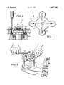
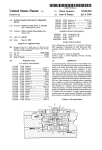
USOO5692282A
United States Patent [191
[11] Patent Number:
Baca
[45]
[54]
SEAL PULLER
[76]
Inventor;
Date of Patent:
Frank M_ Bum 6120 24th St“
3,651,557
3/1972 Bagley .
3,902,236
9/1975 Deem ...................................... .. 29/259
3,909,916
10/1975 N611 et a1. ............................... .. 29/235
4,211,446
Appl- No.1 577,552
[22] Filed:
29/258~ 263~ 282; 81/8-1
,
1/1991 Wendt ..................................... .. 29/264
1?:
$31096
armano e
Attorney Agent, or FiwStcphcn R_ Gfeincf
[57]
ABSTRACT
A seal puller for removing worn seals from transmissions
and like equipment. The seal pullm includes a planar body
References C'ted
Us, PA'I'ENT DOCUMENTS
,
1/1984 Castoe .
4,982,493
Primary Examiner—Robert C. Watson
Int. Cl- .................................................... ..
US. Cl. ................. ..
29/235; 29/259; 29/264
Field of Search ............................ .. 29/259, 235. 256.
[56]
7/1980 Shulz, S11.
4,426,758
Dec. 22, 1995
6
[51]
[52]
[58]
Dec. 2, 1997
3,611,540 10/1971 Gibu ,
Lubbock Tex 79407
[21]
5,692,282
having opposed top and bottom surfaces and a threaded
transverse bore. A plurality are positioned adjacent the
-------------------------- .
transverse bore. A bolt is threadably secured within the
transverse bore. The bolt has a threaded rod portion which
.... ..
3,078,556
2/1963 Carroll
.... .. 29/259
3,200,483
3,340,593
8/1965 Menegoni ............................... .. 29/259
9/1967 Savastano .
3,564,696
2/1971 Shepanski ............................... .. 29/256
-
agorgesgggtggmiogdth? mnsverse b0“ beneath the
y'
4 Claims, 1 Drawing Sheet
I
5
‘i
20
l_ ‘ I. J ‘ 1
5 \
U.S. Patent
34
g
Dec. 2, 1997
5,692,282
F G. 2
28
40 I8
20
36
38
FIG. I
5 1.692.282
1
2
SEAL PULLER
having a gimlet point which may be rotated by a user to
attach the seal puller to a seal. A bolt. threadably secured
FIELD OF THE INVENTION
within the transverse bore. may be rotated by a user to drive
the body of the seal puller from a supporting surface. like the
The present invention relates generally to implements for
drive axle extending from a Barrett tugger transmission. to
extract the attached seal from its seat.
applying pushing and pulling force.
The foregoing and other objects. features and advantages
of the present invention will become readily apparent upon
further review of the following detailed description of the
preferred embodiment as illustrated in the accompanying
BACKGROUND OF THE INVENTION
Motorized vehicles have long been used to move goods
and equipment with minimal effort about warehouses and
other storage facilities. Barrett Industrial Trucks. Inc.. of
Marengo. lll.. has been a leader in the development of such
vehicles. affectionately referred to as “tuggers” by those who
utilize them. Unfortunately. however. the performance of
routine maintenance upon Barrett tuggers to keep them
working at peak e?iciency has never been particularly easy
due to their relative complexity and compact size.
One problem which often arises during maintenance
operations involves the replacement of the drive axle oil
seal. The service manual accompanying the SG 1 24 DF
model tugger. for instance. recommends that a standard
drawings.
BRIEF DESCRIPTION OF THE DRAWINGS
The present invention may be more readily described with
reference to the accompanying drawings. in which:
FIG. 1 is a top view of a seal puller in accordance with the
present invention.
FIG. 2 is a cross-sectional view of the seal puller of FIG.
1 positioned to remove an oil seal from a transmission
20
transmission assembly. a ratchet-type wrench being engaged
service technician. it is suggested. should insert the end of
the screwdriver under the seal lip and use the transmission
housing as a fulcrum to pry the seal loose. This operation is
extremely dif?cult to perform in the con?ned spaces sur
rounding the transmission and typically results in the for
with the lifting bolt.
Similar reference characters denote corresponding fea
tures consistently throughout the accompanying drawings.
mation of undesirable scratches on the seal seat. Prior to
installing a new seal. a ?ne emery cloth or stone must be
used to remove these scratches. Needless to say. much time 30
is lost repairing the minor damage to the transmission
caused by removal of the seal in the recommended fashion.
After the scratches have been polished away. seal replace
ment can typically be accomplished in a straightforward
manner. First. the outer edge of the new seal is coated with 35
liquid gasket cement to ensure against leaks. The open side
of the seal is then packed with grease and the seal is
positioned over the drive axle. The seal is next carefully
tapped into the seat provided therefor in the transmission
characteristics. For increased durability and strength. the
a rigid. ?at. metallic plate.
The body 12 and arms 14 include a number of openings
through their respective surfaces. The center of the body 12
is provided with a transverse bore 18 connecting its top and
bottom surfaces. Equidistantly positioned about the trans
such as those found in Barrett tuggers. it is a principal object
of the present invention to provide a seal puller which can
be used to rapidly remove seals of different sizes from
con?ned areas in a variety of equipment without harm to the
verse bore 18 are a plurality of elongated apertures or slots
50
It is an object of the invention to provide improved
elements. and arrangements thereof. in a seal puller which is
lightweight. inexpensive, dependable and fully effective in
accomplishing its intended purposes.
Brie?y. the seal puller in accordance with the present
invention achieves the intended objects by featuring a planar
body having opposed top and bottom surfaces and a
threaded transverse bore connecting the top and bottom
surfaces. Adjacent the transverse bore. a plurality of elon
gated slots connect the top and bottom surfaces of the planar
body. In each of the elongated slots is positioned a screw
20. As shown. each slot 20 extends radially outward from the
body 12 and partially into an arm 14. Each slot 20 also
extends along the central. longitudinal axis of a correspond
oily environments.
even when the seal puller is coated with oil or grease.
to that of the oil seal 16 being replaced and. thus. shields a
body 12 and arms 14 are preferably cut as a single unit from
SUlVIMARY OF THE INVENTION
It is a further object of the invention to provide a seal
puller which may be readily grasped in the hands of user
the seal puller 10 includes a generally circular body 12
having a plurality of integral arms 14 extending radially
outward from the periphery of the body 12. The diameter of
the body 12 is preferably sized to be substantially equivalent
user from contact with any oil or grease which may be
In light of the problems encountered in removing oil seals
It is another object of the invention to provide a seal puller
which is durable and not subject to erosion or degadation in
DETAILED DESCRIPTION OF THE
PREFERRED EMBODBvIENT
Referring now to FIGS.. a seal puller in accordance with
the present invention is illustrated generally at 10. As shown.
carried by the seal 16 during use of the seal puller 10. The
arms 14. on the other hand. preferably have a length which
may be readily grasped by the ?ngers of a user and are
provided with an ovoid outline to enhance their handling
housing. A properly installed seal will seat substantially
?ush with the outside of the transmission housing.
equipment itself.
assembly.
FIG. 3 is a perspective view of the seal puller on the
screwdriver be utilized to wrest the oil seal from its seat. A
55
ing arm and preferably has a width that is less than twenty
percent of that of the arm at its narrowest location.
A hexagonal nut 22 is secured by a weld 2A to the top
surface of the body 12 so that the central axis of the nut
corresponds with the central axis of the transverse bore 18.
A bolt 26 is threadably secured to the nut 22. As shown. the
threaded rod portion 28 of the bolt 26 is sized to extend
through the transverse bore 18 and outwardly from the
bottom surface of the body 12. The head 30 of the bolt 26
may, of course. be rotated by a conventional ratchet wrench
32 or like device to vary the length of the extension of the
threaded rod portion 28 from the bottom surface of the body
12.
Fitted for axial movement within each of the slots 20 is a
penetrating-type screw 34. As shown. each screw 34
5 £92,282
3
4
includes a threaded shaft 36 that is sized to extend through
a slot 20 and beneath the body 12 or arm 14 (depending upon
arm portions between said inner end thereof and said
the relative positioning of the screw 34 along the length of
the slot). The threaded shaft 36 includes a gimlet point 38 at
planar body portion and foster a strong grip upon
said seal puller;
its free end to assist the screw 34 in penetrating the oil seal
a plurality of screws each being slidably engaged with a
respective one of said slots. each of said screws having
intermediate point thereof will slide toward said
16 in a manner which will be described more fully herein
below. The head 40 of the screw 34 has a diameter greater
a head sized to prevent passage through one of said
than the width of the slot 20 and is. thus. retained against the
top surface of the seal puller 10 during use.
To use the seal puller 10 to remove a worn oil seal 16. the 10
drive wheel (not shown) must ?rst be removed from the
drive axle 42. Next. the body 12 of the puller 10 is positioned
adjacent the worn oil seal 16. Using the seal puller 10 as a
template. the locations of a plurality of small holes to be
threaded rod portion for penetrating a worn seal; and.
a bolt threadably secured within said transverse bore. said
bolt having a second threaded rod portion adapted to be
the slots 20 and the adjacent seal 16. Holes 44 are provided
extended from said bottom surface of said planar body
in the worn seal 16 by drilling with a standard power drill or
portion.
punching with a sharpened awl. As shown. the holes 44 only
penetrate the metallic outer ?ange 46 of the oil seal 16 and
38 of the screws 34 to penetrate the seal 16 and become
20
securely a?ixed thereto.
Once each of the screws 34 have been secured to the worn
seal 16 by rotation of the screwdriver 48. the bolt 26 may be
rotated by a ratchet wrench 32 to drive the threaded rod
portion 28 against the end of the drive axle 42 and lift the
25
seal evenly from its seat 50. The worn seal 16 may be
discarded and replaced with a new seal in the usual fashion.
Although the preferred seal puller 10 is sized to best
accommodate a seal 16 having a 4 inch (10 cm) diameter. it
will assist in removing seals having a diameters ranging
from 2 to 8 inches (5 to 20 cm) due to the adjustability
offered by the elongated slots 20.
While the invention has been described with a high degree
of particularity. it will be appreciated by those skilled in the
intermediate point thereof will slide toward said body
35
desirable to utilize a seal puller having more. or less. than the
four arms 14 illustrated. Further. to reduce the overall cost
of invention. the nut 22 may be eliminated and replaced by
threading the inner peripheral surface of the transverse bore
a threaded transverse bore having a central axis
55
a plurality of arm portions extending outwardly from
said planar body portion. each of said arm portions
having a slot with a longitudinal axis oriented to
intersect said transverse bore. each of said arm
portions also having an inner end secured to said
planar body portion. an outer free end spaced from
said innm' end. and an intermediate point located
between said inner end and said outer free end. each
of said arm portions further having a greater width at
said intermediate point thereof than at said inner end 65
engaged with the opposite sides of any one of said
bolt having a second threaded rod portion adapted to be
projected from said transverse bore beneath said bot
tom surface of said body.
3. The seal puller according to claim 2 wherein said arms
are ovoid in outline for ease of handling by a user.
50
perpendicular to the top and bottom surfaces of said
thereof whereby the ?ngers of a hand of a user
and foster a strong grip upon said seal puller;
a plurality of screws each being slidably engaged with a
respective one of said slots. each of said screws having
a head sized to prevent passage through one of said
slots and positioned atop one of said arms. each of said
screws also having a ?rst threaded rod portion extend
ing from said head and through one of said slots. and
each of said screws further having a gimlet point at the
free end of said ?rst threaded rod portion for penetrat
ing a worn seal; and,
a bolt threadably secured within said transverse bore. said
45
a planar body portion having opposed top and bottom
surfaces. said planar body portion fm‘ther including
planar body portion; and.
each of said arms having a slot with a longitudinal axis
oriented to intersect said transverse bore. each of said
arms also having an inner end secured to said body. an
outer free end spaced from said inner end. and an
intermediate point located between said inner end and
said outer free end. each of said arms further having a
greater width at said intermediate point thereof than at
said inner end thereof whereby the ?ngers of a hand of
art that numerous modi?cations and substitutions may be
1. A seal puller. comprising:
a thin. ?at. metallic plate including:
2. A seal puller. comprising:
a body including opposed ?rst top and bottom surfaces.
said body further including a threaded transverse bore;
a plurality of arms extending outwardly from said body.
a user engaged with the opposite sides of any one of
said arms between said inner end thereof and said
made thereto. For example. the number and location of the
arms 14 and their corresponding slots 20 may be varied in
accordance with need. Thus. in certain applications it may be
18 so as to threadably accept the bolt 26. Therefore. it is to
be understood that the present invention is not limited to the
sole embodiment described above. but encompasses any and
all embodiments within the scope of the following claims.
I claim:
threaded rod portion extending from said head and
through one of said slots. and each of said screws
fln'ther having a gimlet point at the free end of said ?rst
made in the worn seal 16 are marked at the intersections of
have a diameter su?iciently large to permit the gimlet points
slots and being positioned atop one of said arm
portions. each of said screws also having a ?rst
4. A seal puller. comprising:
a planar body including opposed ?rst top and bottom
surfaces being substantially ?at and parallel to one
another. said planar body fln'ther including a threaded
transverse bore connecting said ?rst top and bottom
surfaces;
a plurality of arms extending outwardly from said planar
body. each of said arms having opposed second top and
bottom surfaces coextensive with said ?rst top and
bottom surfaces. each of said arms having a slot with a
longitudinal axis oriented to intersect said transverse
bore. each of said arms also having an inner end
secured to said planar body. an outer free end spaced
from said inner end. and an intermediate point located
between said inner end and said outer free end. each of
said arms further having an ovoid form wherein the
width of each of said arms at said intermediate point
thereof is greater than the width of each of said arms at
5,692,282
5
said inner end thereof whereby the ?ngers of a hand of
a user engaged with the opposite sides of any one of
said arms between said inner end thereof and said
intermediate point thereof will slide toward said planar
body and foster strong grip "P011 Said 3631 Puller;
5
a plurality of screws each being slidably engaged with a
respective one of said slots. each of said screws having
a head sized to prevent passage through one of said
slots and positioned atop one of said arms. each of said
screws also having a ?rst threaded rod portion extend-
6
ing from said head and through one of said slots. and
each of said screws further having a girnlet point at the
free end of said ?rst threaded rod portion for penetrat
ing a worn seal; and.
a bolt threadably secured within said transverse bore. said
bolt having a second threaded rod portion adapted to be
extended from said transverse bore beneath said ?rst
bottom surface of said planar body.
*
*
*
*
*