1
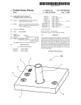
llllllllllllllIIIllillllllllllllllllllllllllllllllllllllllllllllllllllllll
USO05533544A
Unlt€d States Patent [19]
[11] Patent Number:
Good et al.
[45]
[54]
5 9 533 9 544
Date of Patent:
Jul. 9, 1996
SUPPLY BIASED PNEUMATIC PRESSURE
4,898,200
2/1990 Odajima et al. ..
RELAY
4,928,530
5/1990
Lehto etal
. 137/487.5 X
. .. . ..
. . . . ..
4,970,898 11/1990 Walish et a1
[75]
Inventors: Stanley R. Good; Barry L. Gaarder,
,
both of Marshamown’ Iowa
,
gum‘;
I'CSCO “It
e .
5,172,713
[73] Assignee: Fisher Controls International, Inc.,
73/756
73/706
..
12/1992 Hall ................................... .. 251/367 X
FOREIGN PATENT DOCUMENTS
Clayton, Mo.
..
_
[21] APP1- N°-- 456,243
[22] Filed:
May 31’ 1995
0464966A1
3/1991
European Pat. Off. .
0442033Al
8/1991
European Pat. Off. .
2647522Al 11/1990 France.
WO92/22860 12/1992 WIPO.
_
_
OTHER PUBLICATIONS
Related US. Application Data
[60]
Division of Ser. No. 114,955, Aug. 31, 1993, Pat. No.
User’s Manual for the Model 3311 “Current—to—Pressure
(I/P) Transducer”, Publication No. 4595, Rosemount Mea
gts‘g39éo2ltgwllligcghzisg ctzimimtliation-in-paft 0f Ser- N°~ 942’
surement Control Analytical Valves, Sep. 1990, pp. 3—2,
,
Op.6
,
, a an 011E
.
[2;]
................................................... .. GOSDgg/gg
[ 1
[58]
_' ' '
Field of Search ............................................... .. 137/85
[56]
References Cited
Primary Examiner_ Ger31 d A. Michalsky
Attorney, Agent, or Firm-Marshall, 0’T6616, Gerstein,
Murray & Bonm
[57]
US. PATENT DOCUMENTS
ABSTRACT
An electro-pneumatic converter device with modular com
L180’897 4/1916 Williams .
gonents argd witlziiupportmg‘glouimg structure enabling the
2,666,278
1/1954 Matasovic ......................... .. 137/557 X
3,123,094
3/1964 Toschko?"
.. 137/50513
3,245,619
4/1966
“We 1°
6 Tea 1 Y °°nvem 6 Tom a current 1° Pressure
pos1t1oner 19 a cu?em t0 Pr¢$§11rc tr?nsqucer- A valve
Kramer _ _ _ _ _ _
_ _ _ __ 137135 X
pos1t1oner with an enclosure having a houslng, a modular
3,334,642 8/1967 'Borthwick ..
3,349,787 10/1967 Thieme
137/85
137/85
base, and a separable ?eld terminal box. A self contained
cover mounted to the enclosure with no additional mounting
3,842,679 10/ 1974 lwaqet a1 4,172,388 10/1979 Gabmlson
73/423 A
73/721
components. Aplastic pneumatic relay ultrasonically welded
together to eliminate metal mounting parts and lower assem
31:25:21‘
'' ' ' ''‘
4,239,182 12,1980 Amold et a1_ ‘
4,315,432
2/1982
4,329,910
4,399,336
4,453,559
5/1982 Olsen et al. ..... ..
8/1983 dc versterre et a1
6/1984 Vamum ..
Newton . . . . . . . . . .
''‘"
bly time. Open channels in a_ housing surface cooperating
251/612
. . . .. 73/431
glth‘a gasgeth to priniideb?uldppassageways between the
ousmg an
t 6 m0
‘1 ax
‘188
TBS/sure gauges are remov'
91/375 R
137/437_5
137/85
ably mounted 911 a modular ufllt for loci/H1011 qompletely
within the houslng. A ?oating interconnect terrmnal board
permits self-aligning of mating terminals as the modular unit
4,627,286 12/1986 Pehlgrim
73/431
is inserted into the housing. A supply biased pneumatic
‘£653,330
73/756
P ressure relay has supply pressure channeled to the supply
3/ 1937 Hedtke
grown
,
,
rown
port and also to a supply bias cavity through a capillary hole.
..................................... ..
4,819,543
4/1989 Leinen ................................ .. 91/363 R
4,855,659
8/1989 Riensche ............................. .. 137/85 X
<- EXHAUST
\
4 Claims, 14 Drawing Sheets
US. Patent
Jul. 9, 1996
Sheet 1 0f 14
5,533,544
US. Patent
Jul. 9, 1996
Sheet 2 of 14
5,533,544
US. Patent
Jul. 9, 1996
Sheet 3 of 14
F165
5,533,544
US. Patent
Jul. 9, 1996
Sheet 4 of 14
H64
5,533,544
US. Patent
Jul. 9, 1996
FIG4A
48
)
Sheet 5 0f 14
5,533,544
US. Patent
F168
Jul. 9, 1996
Sheet 6 0f 14
5,533,544
US. Patent
Jul. 9, 1996
Sheet 7 0f 14
@QE
%
l52:6'
5,533,544
US. Patent
Jul. 9, 1996
Sheet 8 of 14
F/G. /O
5,533,544
US. Patent
Jul. 9, 1996
Sheet 9 of 14
5,533,544
F/G..//
ZOO
\ 204
2/0
266
384
262
392
406
404 400 4/0
402
US. Patent
Jul. 9, 1996
Sheet 10 0f 14
5,533,544
US. Patent
EAF/G.
206
Jul. 9, 1996
Sheet 11 of 14
5,533,544
U.S. Patent
Jul. 9, 1996
Sheet 12 0f 14
5,533,544
F/G. /5
354 230
D
r
P
344
262
264-\
i
F/G /4
258
350
348
‘i
206
t
/
ML‘!
|
I
I
4! '
274
272
W‘
/
304 ~_%
09259; ‘A
PRESSURE
J
258
)
336
2
/
_3O6
l
I
354
\
I
230
SUPPLY
PRESSURE
5,533,544
1
2
SUPPLY BIASED PNEUMATIC PRESSURE
RELAY
linkage with the valve stem. Both analog valve positioner
units and digital valve controller units are separately avail
able.
This is a divisional of application Ser. No. 08/114,955,
?led Aug. 31, 1993, now U.S. Pat. No. 5,439,021, which is
Typically, the customer chooses the type of instrument
needed in order to ?t within his present system. Thus, a
customer may initially choose to purchase a pressure trans—
a continuation-in-part of application Ser. No. 07/942,758,
?led Sep. 9, 1992, abandoned.
This invention relates to pressure relay devices and in
particular to supply biased pneumatic pressure relays useful
in current to pressure transducers and valve positioner
devices.
10
chased a pressure transducer instrument, he must purchase a
new valve positioner device in the proper data format to ?t
BACKGROUND OF THE INVENTION
Electro-pneumatic converters, such as current to pressure
his changed system.
transducers are in common use as ?eld instruments mounted
It is therefore further desired to provide an electro
in pipeline systems for controlling the process ?uid. Sub
pneumatic instrument which is usable and readily convert
sequently these devices are installed in potentially hazardous
explosive environments. Such devices receive, for example,
a variable current input signal of between 4-20 mA and
eventually provide a variable pressure output to an actuator
20
ible from a pressure transducer to a valve positioner or vice
versa. In addition, it is desired to enable a user to readily
convert from an analog data handling capability to a digital
data handling capability or vice versa. Furthermore, it is
for a ?uid control valve. Since these devices can be
employed in a potentially explosive environment, to provide
an explosion proof device the electrical and pneumatic
components are isolated within an explosion proof portion
ducer instrument in analog form as most conveniently
adaptable to his present system. If the customer’s system
changes or he wishes to modify his system to operate in
digital form, the customer must then purchase the required
separate instruments. Also, if the customer wants to change
to a valve positioner con?guration when he initially pur
desired to enable the instrument user to incorporate and to
change to any desired communications data protocol.
25
of the transducer/positioner unit, except for the pressure
In existing electro-pneumatic instruments, the instrument
housing is usually formed of a casting. The casting must then
be drilled with precise holes to form passageways and
gauges which are normally located on the unit exterior.
interconnected passageways to enable the desired commu~
With presently available electro-pneumatic converters
operating in a potentially explosively hazardous area, in the
nication of ?uid between components. Forming of the
event either service of the unit or normal maintenance is 30
required, the electric power must be disconnected and/or the
entire unit must be removed from the potentially hazardous
desired passageways by drilling intersecting holes in the
casting requires time consuming precision drilling and set up
of the housings for drilling. Present instruments also utilize
many individual sub-assembly components requiring stock
area in order to be worked on. Occasionally, for instance, the
ing and assembly time. The instrument covers, for instance,
pneumatic elements must be adjusted or removed and
normally require two or more pins and locks or other
replaced. In present units, if the seal of the explosion proof 35 multi-part fasteners to mount the cover to the instrument.
portion of the unit is removed in order to get access to these
This requires an inventory of the several parts and an
pneumatic elements, then a potentially unsafe condition is
created where any spark caused in the electrical elements
inordinate amount of assembly time to assemble the cover to
the instrument.
could ignite potentially explosive gases. Accordingly, shut
ting down the electrical power in order to service or remove 40
the unit from the hazardous area is time consuming, costly,
based materials. Machine screws are used to assemble the
and wasteful.
In addition, with the electrical and pneumatic components
maintained within an explosion proof portion of the trans
ducer/positioner unit, the mounting of the pressure gauges
on the portion outside the explosion proof portion of the unit
is required. However, this exposes the pressure gauges to the
atmosphere as well as to physical damage from uninten
tional blows to the pressure gauges protruding even slightly
from the transducer/positioner exterior surface.
Accordingly, it is desired to provide an electro-pneumatic
Pneumatic relays, used extensively in positioners and
transducers, normally have been made from aluminum
aluminum relay body components together while clamping
rubber diaphragms and O-rings to provide the pressure seals.
Assembly of these numerous sub-assembly components of
present pneumatic relays is tedious and costly in the manu
facturing environment.
It is desired therefore to eliminate components or at least
reduce the number of components required for an electro
50
pneumatic instrument.
SUMMARY OF THE INVENTION
converter which can be used in a potentially explosive
In accordance with the present invention there is provided
environment and wherein pneumatic components can be
serviced without requiring electrical shutdown or removal of 55 a versatile modular con?guration for an electro-pneumatic
the entire unit from the hazardous area.
instrument that can serve as a platform of construction for a
In addition, it is desired to provide an electro~pneumatic
converter where the pressure gauges can be protected from
the atmosphere as well as from any unintentional physical
wide range of output devices which includes, for example:
a digital pressure transducer; a digital valve controller; an
analog valve positioner; and an analog pressure transducer.
All of the aforementioned output devices available from the
present invention can provide the following features:
damage.
60
Currently available pressure transducer instruments con
1. A modular con?guration with a ?eld termination com
partment, an electronics compartment, and a pneumatic
tain a pressure to current sensor to convert a pressure signal
to a current signal in supplying feedback to the instrument.
Analog pressure transducer units are available, as well as
respective digital pressure transducer units. Also currently
available are separate valve positioner units which incorpo
rate feedback from the valve supplied from a mechanical
65
compartment which are all environmentally segregated from
each other;
2. A modular con?guration which is explosion proof, and
allows maintenance and serviceability of the pneumatic
5,533,544
3
4
elements without interfering with the electrical components;
a closed con?guration and yet can be readily removed from
the module base if desired in an open con?guration.
In accordance with a further aspect of the present inven
and
3. A modular con?guration permitting user selected varia
tions in feedback and mountings to accommodate both
sliding stem valve actuators and rotary shaft valve actuators.
tion, there is provided a pneumatic relay with plastic molded
structural body components. These components are ultra
sonically welded together in a manner that clamps the
diaphragm to provide the pressure seals, thus eliminating the
need for machine screws. Thus, the number of sub~assembly
components are minimized and the assembly costs for the
In accordance with the principles of the present invention,
there is provided an electro-pneumatic instrument of modu»
lar construction which is readily convertible from a pressure
transducer to a valve positioner and vice versa. In the
preferred embodiment of the invention, the convertible
pneumatic relay are drastically reduced by almost one-half.
instrument includes an enclosure having a housing de?ning
a hollow interior, and a modular base containing electrical
and pneumatic components, where the modular base is
There is also provided an electro'pneumatic converter in
the form of a current to pressure transducer/positioner unit
having an enclosure which includes a housing and module
removably insertable into the housing. A housing portion is
included on the housing and is adapted for receiving and
mounting therein a potentiometer and shaft in converting the
15
instrument to a valve positioner. The housing portion com
municates with the hollow interior to enable the potentiom
eter output to be connected to the electrical components on
the modular base via the housing portion and the housing
direction. This segregated compartment preferably contains
the electrical components. Another segregatedv compartment
The housing portion may be formed of an elongated
cylindrical boss extending along the housing and which
is de?ned between the dividing interior wall and a second
includes a pocket interior to receive the potentiometer at one
25
interior and a bushing is threadably mounted on the elon
portion of the module base opposite the dividing interior
wall in a second direction opposite from the ?rst direction
for preferably containing the pneumatic components iso
gated cylindrical boss to supportably mount the potentiom
lated from the electrical components.
A removable cover is preferably provided for the segre
eter shaft.
In converting a valve positioner utilizing the present
gated compartment containing the pneumatic components.
electro-pneumatic instrument of the present invention to a
pressure transducer, this can be readily provided by remov
Accordingly, removing the cover enables access to the
ing the potentiometer from the housing portion, disconnect
ing the potentiometer output cable from the main printed
circuit board mounted on the modular base, and replacing
the main circuit board to accommodate the signals appro—
partmented portion of the unit forming two segregated
compartments for the respective electrical and pneumatic
components. A dividing interior wall between opposite sides
of the module base de?nes a segregated compartment
between the dividing interior wall and a ?rst portion of the
module base opposite the dividing interior wall in a ?rst
hollow interior.
end. The pocket interior intersects with the housing hollow
base for electrical and pneumatic components with a com
35
pneumatic component segregated compartment for servicing
the pneumatic components while maintaining the electrical
components isolated. Therefore, with the present invention,
the explosion proof electronic compartment remains isolated
and undisturbed and all of the explosion proof elements can
remain intact while one services the pneumatic elements in
The preferred embodiment also includes an electrical
the unit of the present invention. Thus, there is no need to
terminal box mounted on the housing with a passageway
disconnect the electrical power while working on the pneu
between the housing interior and the terminal box. An 40 matic elements in the unit of the present invention.
electrical terminal board is replaceably mounted in the
The signi?cant advantage of this aspect of the invention
terminal box which includes a removable cover for access
includes the ability to adjust or remove and replace the
thereto. A cable harness is connected to the electrical ter
pneumatic elements while the power is connected without
minal board in the terminal box and extends through the
breaking the seal of the explosion proof portion of the
passageway and the housing hollow interior for connection 45 transducer/positioner. Other signi?cant advantages include
to the main circuit board on the modular base. The terminal
the ability to provide additional maintenance features, such
board and cable harness are replaceable to accommodate
as stroking the pneumatic elements fully opened or closed to
corresponding desired formats and functions, such as ana
perform maintenance diagnosis of the unit. The pneumatic
log, digital, communication or data protocols.
elements can also be adjusted to change pneumatic zero
In accordance with another aspect of the present inven 50 during maintenance or troubleshooting. Also, access to the
priate to a pressure transducer as is known in the art.
tion, a housing is provided with a substantially ?at housing
supply pressure primary restriction which may become
clogged and requires cleanout is readily provided in accor
mounting surface with open channels or slots within the
surface. A modular base has a modular base mounting
surface opposite to the housing mounting surface. A gasket
is provided intermediate the housing mounting surface and
the modular base mounting surface. The gasket covers the
open channels so as to de?ne the housing ?uid passageways,
55
dance with this invention.
In accordance with another aspect of the present inven
tion, an electro-pneumatic converter unit includes an enclo
sure having a housing de?ning a hollow interior and a
modular base removably insertable into the housing hollow
and further includes apertures for communicating the hous
interior so as to be surrounded by the enclosure. Electrical
ing ?uid passageways to the modular base ?uid passage
and pneumatic converter components are mounted on the
ways. A distinct advantage of this aspect of the invention is 60 modular base including one or more pressure gauges so that
the elimination of the need to drill precise holes through the
the pressure gauges are located within the enclosure and
housing or to precisely locate and drill intersecting holes to
thereby protected from the environment and any physical
form the desired ?uid communicating passageways.
damage. The gauges, which are mounted in the pneumatic
In accordance with still another aspect of the present
compartment are in an atmosphere which is constantly being
invention, there is provided a cover with self-contained 65 purged by the supply pressure medium, thus aifording them
mounting ears shaped for ease of inserting the ears into the
additional protection to corrosive atmospheres not seen with
module base so the cover is retained on the module base in
devices with externally mounted pressure gauges. The pres
* 5,533,544
5
6
sure gauges are preferably threadably mounted on the modu
FIGS. 12 and 12A are exploded perspective views of the
modular con?gured valve positioner of FIG. 10, the two
lar base for ease in servicing and replacement.
In accordance with still another aspect of the present
invention, the modular base includes a dividing interior wall.
First means are provided for mounting the electrical com III
ponents on one side of the dividing interior wall. Second
means are provided for mounting the pneumatic components
including pressure gauges on the opposite side of the divid
ing interior wall. Accordingly, as the modular base is insert
ably mounted into the housing interior, segregated compart—
10
ments are de?ned for respectively isolating the electrical
components from the pneumatic components.
In accordance with still another aspect of the invention
there is provided an improved pneumatic pressure relay for
arrowheads;
FIG. 13 is an elevational view showing a modular base
with some components removed for clarity;
FIG. 14 is a sectional view taken along section lines
14—14 of the modular base shown in FIG. 13;
FIG. 15 is a fragmented view partly in section showing a
pressure sensor sensing the output pressure;
FIG. 16 is an elevational view of the instrument housing
portion showing channels in the surface for ?uid passage
ways;
FIG. 17 is an elevational view of the modular base
a ?uid actuator control valve assembly. The supply pressure
is communicated to a supply bias cavity through a capillary
hole to maintain a substantially constant supply pressure of
the relay. Pressure transients in response to load changes are
isolated from the supply bias cavity by the capillary hole.
?gures being consecutively locatable along the same central
reference axis along the direction indicated by the respective
20
showing the modular base surface facing the housing surface
of FIG. 16; and
FIG. 18 is a schematic block diagram illustrating the
electro-pneumatic converter instrument readily convertible
from a valve positioner to a pressure transducer and vice
BRIEF DESCRIPTION OF THE DRAWINGS
versa.
The features of this invention which are believed to be
novel are set forth with particularity in the appended claims.
The invention may be best understood by reference to the
following description taken in conjunction with the accom
panying drawings, in which like reference numerals identify
like elements in the several ?gures and in which:
DETAILED DESCRIPTION
25
The modular and convertible aspect of the invention
illustrated in FIGS. 1—9 will be described in connection with
an embodiment comprising a current to pressure transducer.
It is to be understood that the teachings herein can as well
FIG. 1 is a front elevational view illustrating a current to 30 be applied to other electro-pneumatic converter devices to
solve problems similar to those which are solved by the
pressure transducer having an enclosure with a housing and
present invention. As an example, while this description is in
a removable module base in accordance with the present
connection with a current to pressure transducer, it is well
invention;
known in the art that such devices can readily be converted
FIG. 2 is a cross-sectional view taken along section lines
2—2 of the current to pressure transducer shown in FIG. 1, 35 to a current to pressure positioner following the teachings
herein.
with certain components removed for clarity;
The ?exible modular and convertible aspect of the inven
FIG. 3 is a sectional view of the module taken along
tion illustrated in FIGS. 10-18 will be described in connec
section lines 3—-3 of the current to pressure transducer
tion with a preferred embodiment comprising a current to
shown in FIG. 1, with certain components removed for
pressure positioner which is more readily convertible to a
clarity;
current to pressure transducer and vice versa than the
FIG. 4 is a sectional view taken along section lines 4-—4
of the current to pressure transducer shown in FIG. 2, with
embodiment of FIGS. 1—9. Accordingly, the present descrip~
certain components removed for clarity;
FIG. 4A is a fragmentary sectional view taken along
45
section lines 4A——4A of the current to pressure transducer
shown in FIG. 1;
FIG. 5 is a fragmented sectional view taken along section
lines 5——5 of the current to pressure transducer shown in
the teachings herein.
I. Convertible Current To Pressure Transducer
FIG. 1, with certain components removed for clarity;
Refening now to FIGS. 1 and 2, there is illustrated a
current to pressure transducer 10 having an enclosure which
includes a housing 12 with one portion de?ning a hollow
interior 14. The housing 12 includes a ?eld terminal box
FIG. 6 is an elevational view showing an interconnect
board for connecting electrical terminals;
FIG. 7 is an elevational view showing the interior of the
housing with the interconnect board ?oatably mounted
therein;
55
from the housing so that the appropriate cable wiring
60
FIG. 10 is a perspective view of a preferred embodiment
of the invention illustrating a valve positioner in modular
con?guration which can be readily converted to a pressure
transducer;
FIG. 11 is a sectional view of the preferred embodiment
of the invention taken along section lines 11—l1 of the
valve positioner shown in FIG. 10;
portion 16 including a ?eld terminal strip 18 for suitable
connection to an electrical signal cable for receiving a
current control signal from a distributing control system, so
as to for instance monitor a process. End cap 20 is removable
FIG. 8 is a schematic sectional view showing a shoulder
screw mounting the interconnect board in a ?oating manner;
FIG. 9 is a sectional view showing a supply biased
pneumatic pressure relay;
tion is to be understood to be for purposes of describing the
preferred embodiment and is not meant to limit the scope of
the invention and the claims. Thus, the invention and the
claims are to be given a broad interpretation consistent with
65
connections can be made to terminal 18.
Housing 12 also includes an inlet 22 for receiving a
supply pressure from a pneumatic supply source, and an
outlet port 24 through which the output pressure can be
suitably coupled to a positioner or directly to a valve
actuator. Typically, in response to a variable 4—2O mA
current control signal, current to pressure transducer 10
provides a variable pressure output at outlet 24.
5,533,544
7
8
A modular base 26 (see FIG. 3) contains the electrical
components and the pneumatic components for current to
pressure transducer 10. Typically, this will consist of a
mount and seal the metal base 28 through O-rings 32 with
respect to housing 12.
In accordance with one aspect of the present invention, it
may be noted that while the pressure components and the
electrical components have been isolated within the enclo
sure formed by housing 12 and modular base 26 to prevent
any inadvertent spark from the electrical components to
current to pressure converter device such as a I/P nozzle
block having a ?apper for converting the variable current
control signal input into a variable nozzle pressure signal; a
pressure relay receiving the variable nozzle pressure signal
and providing a variable pressure output on outlet 24; a
ignite potentially hazardous environments which may be
pressure gauge monitoring the supply pressure coupled to
inlet port 22; a second pressure gauge monitoring the
present in the pressure components, yet the pressure com
ponents can be serviced and maintained without shutting
pressure output on outlet 24; and electronic equipment such
down the power or requiring removal of unit 10 from the
as a pressure sensor and a printed circuit board with circuitry
potentially hazardous area. With respect to this aspect of the
to process the electrical signals as required.
present invention, note that removal of cover 38 and mask
Modular base 26 includes a metal base 28 having a
36 from the enclosure provides access to the pressure
threaded ring 30 and O-rings 32 so that modular base 26 can
components within pressure compartment 40 while still
be inserted into housing 12 by threadable engagement. 15 maintaining the isolation of the electrical components in
Reference may be made to FIG. 2, wherein modular base 26
electrical compartment 42.
is shown in its complete threadable mounting position when
fully inserted within housing 12.
Thus, the UP nozzle block 46 can be serviced without
turning o?’ the electrical power. For instance, the pneumatic
The modular base also includes a modular wall 34 which
provides the mounting of the pressure components on one
side and the electrical components on the other side. In the
modular base 26, and opposite wall 34, there is provided a
masking plate 36 and a clear cover plate 38 forming a
pressure compartment 40 in the modular base and de?ned
between modular wall 34 and cover plate 38. With reference
elements can be adjusted to pneumatic zero during mainte
nance or troubleshooting by affording access to a zero
to FIG. 2, it can be seen that when the modular base is
adjustment nut 70 on the UP nozzle block unit. Also, access
is permitted to a cleanout wire 72 to permit the wire to be
used to cleanup the pneumatic restriction or ori?ce in the air
supply line which can become clogged. In a similar manner,
the pressure gauges can be threadably removed from the
insertably mounted into the housing, an electrical compart
ment 42 is de?ned as part of housing interior 14 and is
speci?cally de?ned between modular wall 34 and a housing
side 44.
module and replaced, if necessary, without shutting o?’ the
power supply. Servicing of the pneumatic relay can also be
performed with the complete isolation of the electrical
components in electrical compartment 42.
25
30
With reference to FIGS. 1-3 it can be seen that the
pressure components are mounted in the modular base on
In accordance with another aspect of the present inven
tion, it may be noted that pressure gauges 50 and 52 are
one side of modular wall 34 and the electrical components
are mounted on the other side of wall 34. For example, an
mounted totally within the enclosure formed by housing 12
HP nozzle block-?apper unit 46, a pneumatic relay 48, and
35
pressure gauges 50, 52 are all mounted in pneumatic com
partment 40 on one side of wall 34. A printed circuit board
54 containing electrical components and a pressure sensor
56 are mounted on the opposite side of modular wall 34 so
that they are con?ned within electrical compartment 42
and modular base 26 so they are not subject to the environ
ment or to any physical damage from actions outside of the
housing. Yet, the pressure gauges can be removed or are
subject to repair by removing replaceable cover 38 and mask
36 to provide access to pressure compartment 40.
FIG. 4 illustrates the modular wall 34 which contains a
longitudinal passageway to communicate the inlet pneu
matic supply at an inlet end 76 into I/P nozzle block 46 and
to communicate the UP nozzle block variable pressure
when the modular base is inserted into the housing.
Accordingly, as can be seen from FIG. 2, the electronic
output into the pneumatic relay 48. Referring now to FIG.
components are isolated within segregated electrical com
partment 42 and the pressure components are isolated in 45 4A, there is illustrated modular wall 34 and the passageways
through the modular base for connecting the supply pressure
segregated pressure compartment 40 on opposite sides of
from inlet end 76 to passageways 77 and 79 to the UP nozzle
modular wall 34. All of the electrical and pneumatic com
block 46 from the main supply passage 81. The variable
ponents, including the pressure gauges, are maintained
pressure output of nozzle block 46 is supplied through a
within the instrument enclosure. It is understood, of course,
passageway 83 to interconnecting passageway 74 to the
that suitable explosion preventing devices are inserted in the
ori?ces through wall 34 which may otherwise interconnect
pneumatic relay 48.
compartments 40 and 42. As an example, with reference to
With reference to FIG. 3, it can be seen that passageway
81 connects to a transverse passageway 85 at the inlet end
FIG. 3, aperture 58 through wall 34 interconnects pressure
gauge 52 and pressure sensor 56. A commercially available
item known as a ?ame arrester 60 is inserted in aperture 58.
The ?ame arrester 60 may comprise a porous metal plug
which allows pressure to pass through the plug but which
will cool and lower the temperature of any ?ame in aperture
76 for eventual communication with inlet port 22 for receiv—
55
58 to prevent ignition of potentially hazardous environ
ments.
60
Threaded ring 30 is free to rotate with respect to metal
base 28. The threaded ring is securely captured between
engage a threaded housing portion 68 so as to securely
With reference to FIG. 4, apertures 78 are shown in the
modular wall to permit the electrical connections from
printed circuit board 54 through the modular wall to the UP
nozzle block. As indicated previously, these apertures also
contain suitable explosion proof seals to isolate and prevent
any sparks in electrical compartment 42 from causing igni
tion of potentially hazardous environment through the wall
metal base 28 on one side and two stanchions 62 mounted
to metal base 28 and having a projecting ledge 64 slightly
spaced from a rim 66 of threaded ring 30.
This enables the threaded ring to rotate and threadably
ing the pneumatic supply pressure when the modular unit is
mounted in the housing.
65
34 and into pressure compartment 40.
In accordance with another aspect of the present inven
tion, the mating of connections between the housing termi
nals and the modular terminals is provided by a blind
5,533,544
10
connection, i.e. automatically as modular base 26 is insert
ably mounted into housing 12. The electronic components
a potentiometer. For a transducer unit, a plug 120 is thread
on printed circuit board 54 are electrically connected to a
compartment 42. When the unit is to be used as a positioner,
a potentiometer can be mounted in the electrical compart
ment for electrical connection to connectors 118 and with
ably mounted into housing side 44 to close off electrical
modular terminal strip 80 containing modular terminals 82,
which as shown in FIG. 5 consist of a plurality of male
terminal pins. Printed circuit board 54 is mounted within a
the potentiometer shaft extending through an aperture with
suitable ?ame arresting devices in a plug.
plastic cover 84, preferably by epoxy molding of all of the
units within the plastic cover. Cover 84 is in turn mounted
to modular wall 34 through the use of appropriate threaded
screws 86. As shown in FIG. 5, modular terminals 82
Referring now to FIG. 9, there is illustrated an improved
pneumatic pressure relay 48 which receives a variable
protrude through cover 84 for engagement with female
housing terminals 88 contained on a housing terminal strip
pressure on outlet 124 coupled to pneumatic outlet 24 of
housing 12 (see FIG. 1) for communication with a valve
actuator. Relay 48 also includes a supply pressure inlet 126
coupled to the inlet 22 of housing 12 (see FIG. 1) for
connection to a source of pneumatic supply pressure. Relay
control pressure on inlet 122 and delivers a variable output
90 which in turn is mounted to a housing interconnect board
92.
With reference to FIGS. 6 and 7, there is indicated the
manner in which the housing interconnect board is ?oatably
mounted so as to permit self-aligning of the board with the
modular terminal pins. Housing side 44 includes a pair of
upright ribs 94 each having a threaded aperture for receiving
a respective mounting screw 96. Preferably, mounting
48 also includes an exhaust outlet 128.
Pneumatic pressure relay 48 includes a supply bias por
tion for establishing the start point of the pneumatic pressure
input range at inlet 122 for a given supply pressure at inlet
20
screws 96 are shoulder screws so that the bottom of the
shoulder butts against the rib and prevents further penetra
tion of the shoulder screw into the threaded aperture of the
rib.
Referring to the schematic illustration of FIG. 8, this
con?guration is illustrated in more detail. Threaded aperture
98 within rib 94 receives a threaded portion 100 of screw 96
until a shoulder 102 compressingly abuts against rib 94. As
seen in FIG. 8, the length of shoulder 102 is greater in
dimension than the width of housing interconnect board 92.
Therefore, the housing interconnect board can ?oat longi
tudinally along screw 96 and between the screw head and the
top of rib 94. If desired, screw head 96 can be sized for this
purpose or, a larger washer 106 may be utilized. In addition,
apertures 104 in housing interconnect board 92 are made
slightly larger in diameter than the diameter of shoulder 102.
This permits the interconnect board to slightly move trans
versally with respect to the screw. Thus, housing intercon
nect board is securely captured by screw 96 and ribs 94 but
is allowed to ?oat in position between the screw and the rib
so that the housing terminals are self-aligned with the
25
movement of diaphragm 130 in response to the variable
pressure input on inlet 122 controls the opening and closing
of the input supply and exhaust ports. A valve rod 136
includes a supply valve plug 138 at one end and an exhaust
valve plug 140 at the other end.
A valve spring 142 seated against plug 138 and cap 144
normally maintains plug 138 seated against input supply
port 132 as shown in FIG. 9. This blocks the supply pressure
from inlet 126 from reaching the actuator outlet 124 which
supply pressure otherwise would communicate through pas
sageways 146, 148, through an open input supply port 132
and through a passageway 150 to actuator outlet 124.
The drive coupling between input signal diaphragm 130
40
modular terminals during the insertable mounting of modu
lar base 26 into the housing.
To guide the modular terminals in the correct orientation
with respect to the housing terminals, a longitudinal groove
108 is provided on the inside surface of the housing. Groove
108 matches an indexing pin 110 which is ?xed within the
outer surface of metal base 28. Thus, in inserting modular
base 26 into the housing, the modular base is rotated until
indexing pin 110 is ?tted within longitudinal groove 108 to
126. The start point input pressure will change with chang
ing supply pressures and therefore allows the relay 48 to
operate at different supply pressures without hardware
changes, such as bias springs. With reference to FIG. 9, it
may be seen that relay 48 includes an input signal diaphragm
130, an input supply port 132, and an exhaust port 134. The
45
and valve rod 136 is provided through three intermediate
diaphragm mounting bodies, namely an upper body 152, a
middle body 154 and a lower body 156. An upper supply
bias diaphragm 158 is captured between bodies 152, 154 and
a lower supply bias diaphragm 160 is captured between
middle block 154 and lower block 156.
A supply bias cavity 162 is de?ned between diaphragms
158, 160, middle block 154 and an outer casing 155. A small
capillary hole 164 through casing 155 communicates the
supply bias cavity with supply pressure inlet 126 so that the
50
supply bias cavity is substantially always under the supply
pressure. Thus, the supply pressure is not only channeled to
correctly position modular terminals 82 with the housing
input supply port 132, but also enters supply bias cavity 162
terminals 88. Thereafter, as threaded ring 30 is rotated to
move the modular base into the housing, because of the
via capillary hole 164. It is desirable that once the supply
pressure is established in cavity 162, that it not change
?oating mounting of housing interconnect board 92, the
female housing terminals 88 become self-aligned with the
55
male modular terminals 82 to achieve the ?nal electrical
interconnection of the modular base with the housing inter
connect board as shown in FIG. 5.
during the operation of relay 48. Momentary ?uctuations in
the supply pressure can result when supply port 132 is
opened and closed. The capillary hole isolates the supply
bias cavity from pressure transients created when valve plug
138 opens or closes supply port 132 in response to load
A ?exible electrical cable 112 interconnects the housing 60 changes. This effectively stabilizes the valve assembly when
brief pressure ?uctuations occur due to input signal changes
interconnect board 92 with a small printed circuit board 114
which in turn is connected to a series of RFI ?lters 116 with
the ?lters 116 connected through housing 12 to appropriate
?eld terminals 18.
-
Since the transducer unit can readily be converted to a 65
positioner as known in the art, housing interconnect board
92 also includes suitable connections 118 for connection to
thereby resulting in improved performance.
FIG. 9 illustrates relay 48 in its normal position. When an
increasing variable pressure is coupled to inlet 122, input
signal diaphragm 130 is ?exed upwardly in FIG. 9 to move
bodies 156, 154, 152, exhaust plug 140, rod 136 and valve
plug 138 also upwardly to unseat the supply port 132.