1
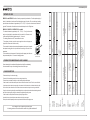
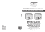
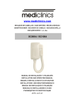
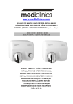
www.saniflowcorp.com
HAND DRYERS
04 / 04
M02A-UL / M02AC-UL / M02ACS-UL
M03A-UL / M03AC-UL / M03ACS-UL
USA
SPAIN
SANIFLOW CORPORATION
2655 LeJeune Rd.,
Suite 810. Coral Gables, FL 33134.
Tel.: 305 424 24 33
Fax: 305 424 24 35
[email protected]
www.saniflowcorp.com
MEDICLINICS, S.A.
Industria, 54
E-08025BARCELONA
Tel.: +34 93 446 47 00
Fax: +34 93 348 10 39
[email protected]
www.mediclinics.com
Cod.: 82917UL
INSTALLATION AND OPERATING MANUAL
www.saniflowcorp.com
INSTALLATION
Dismantling for installation
• The hand dryer is supplied with the metallic cover coupled to the base in a unscrewed stated.
• The cover should be extracted taking into account its upper rib placed in its fitting on the base.
• The cover must be removed obliquely until the upper rib has been extracted.
Take care to avoid:
• Damaging the internal parts (mainly electronic components)
• Damaging the cover. It is recommended placing it on a flat
surface facing upwards and on a cloth.
Mounting
The assembly should be preferably prepared for rear ducting.
• Drill holes of 5/16” (8 mm) in the wall, using the template
supplied. Clean the holes of the resulting dust and insert
the plugs.
• Pass the power cables from the wall through the 7/8”
(22 mm) hole situated beneath the connection board of
the appliance.
• Screw the base of the appliance tightly to the wall ensuring
the 4 silent-blocks are correctly positioned.
• Enter the power cables and earth wire into the inside
space containing the terminal strip, passing them through
the entry hole.
• To reach the terminal strip the protective top should be
opened.
• Connect the cables from the mains and earth wire to their
locations in the terminal strip. Once the electrical connection
has been made, close the protective cover again.
• Fit the metallic cover into the base, placing it from top to
bottom with a certain inclinations. Make sure the upper
rib has entered in their location in the base.
• Place the lower screws, tightening with the specially
supplied key.
1
Upper ribe
Location in the base
6
www.saniflowcorp.com
WARRANTY
·
WARRANTY
·
WARRANTY
LIMITED WARRANTY
This Product covered by this limited warranty is warranted to be free
from defects in material and workmanship under normal conditions
for a period of ten years from the date of purchase.
The manufacturer’s obligation under this Limited Warranty is applicable
only where a product defect has been claimed during the warranty
period. The manufacturer’s obligation under this Limited Warranty is
limited to either (I) replacement of the Product; or (II) replacement
of defective parts. To claim under this Limited Warranty, contact one
of Mediclinics, S.A. official dealers.
Mediclinics, S.A. shall not be responsible for any other damage, including,
but not limited to, any defects or damage caused by or resulting from:
(a) alterations to the product; (b) use of the product in an incorrect
manner or for an unreasonable use; (c) failure to use the product in
a safe and reasonable manner, and (d) repair of the product by
unauthorized personnel.
LIMITATION ON LIABILITY
THE WARRANTY SET FORTH ABOVE IS EXCLUSIVE AND NO OTHER
WARRANTY, WHETHER WRITTEN OR ORAL, IS EXPRESSED OR IMPLIED.
MEDICLINICS, S.A. SPECIFICALLY DISCLAIMS THE IMPLIED WARRANTIES
OF MERCHANTABILITY AND FITNESS FOR A PARTICULAR PURPOSE.
IN NO EVENT SHALL MEDICLINICS, S.A. BE LIABLE FOR INDIRECT,
SPECIAL, INCIDENTAL OR CONSEQUENTIAL DAMAGES (INCLUDING,
BUT NOT LIMITED TO, LOSS OF PROFITS, LOSS OF CUSTOMERS, LOSS
OF USE, DAMAGE TO GOODWILL OR TO BUSINESS REPUTATION) OR
FOR ANY OTHER LOSSES FROM ANY CAUSE, INCLUDING DAMAGES
CAUSED BY THE PRODUCT, WHETHER OR NOT MEDICLINICS, S.A. HAS
RECEIVED NOTICE OF THE POSSIBILITY OR CERTAINTY OF SUCH
DAMAGES OR LOSSES.
SOME STATES DO NOT ALLOW THE EXCLUSION OF INCIDENTAL OR
CONSEQUENTIAL DAMAGES, SO THE ABOVE LIMITATION OR EXCLUSION
MAY NOT APPLY TO YOU. THIS WARRANTY GIVES YOU SPECIFIC LEGAL
RIGHTS, AND YOU MAY ALSO HAVE OTHER RIGHTS WHICH VARY
FROM STATE TO STATE.
GARANTIA
5
·
·
WARRANTY
·
GARANTIE
·
WARRANTY · WARRANTY · WARRANTY · WARRANTY · WARRANTY · WARRANTY
·
WARRANTY · WARRANTY · WARRANTY · WARRANTY · WARRANTY · WARRANTY
·
WARRANTY
www.saniflowcorp.com
WIRING DIAGRAM
MO2A-UL, MO2AC-UL and MO2ACS-UL models
ELECTRIC DIAGRAM
M
H
ELECTRIC DIAGRAM
MO3A-UL, MO3AC-UL and MO3ACS-UL models
M-
Motor
M
M-
Motor
S-
Sensor
H
S-
Sensor
H-
Heating element
H-
Heating element
S
S
CONNECTION TO ELECTRONIC CARD
CONNECTION TO ELECTRONIC CARD
H(C)- Black heating element wire
H (C)
H (L)
H(H)
Power supply wires
110-120V
50/60Hz
H(C)- Black heating element wire
H (C)
H(L)- White heating element wire
H (L)
H(L)- White heating element wire
M- Motor wire
Power supply wires
H(H)- Red heating element wire
110-120V
50/60Hz
M- Motor wire
Connection wires to IR E/R sensor circuit
Connection wires to IR sensor circuit
BREAKDOWN LIST OF BASIC PARTS
MO2-UL & MO3-UL
MO2-UL
MO3-UL
4
RC82770UL
RC82720UL
Electronic circuit set
5
RC82600UL
RC82610UL
IR sensor circuit
6
RC82601UL
Main electronic card
7
Coal brushes set
8
White painted steel cover
1
RC82010
Satin finish stainless steel cover
1
RC82020
Bright finish stainless steel cover
1
RC82030
Motor
2
RC82748UL
Fan wheel
3
RC82777
Heating element
RC82602UL
RC95750-AMT
RC95750-STC
6
4
2
3
7
1
5
8
GARANZIA
2
www.saniflowcorp.com
3
Chrome satin
UL 499
318 CFM (9,005l/min)
5,195 LFM (95 Km/h)
120ºF (50ºC)
Certified in
accordance with:
Air flow :
Air velocity
Air temperature
Chrome bright
White Epoxy enameled
Chrome satin
Chrome bright
White Epoxy enameled
Finish
Stainless Steel
1/6” (1.5mm)
Steel
5/64” (1,9 mm)
Steel
5/64” (1,9 mm)
COVER:
Type
Thickness
Stainless Steel
1/6” (1.5mm)
12.8” (325 mm)
10.7” (272 mm)
6.5” (164 mm)
12.6” (320 mm)
10.7” (272 mm)
6.5” (164 mm)
TIMER:
Type
DIMENSIONS:
Height
Widht
Depth
IR sensor & µ-processor
0 ÷ 2.7 Hp (0 ÷ 2000 W)
12.8” (325 mm)
10.7” (272 mm)
6.5” (164 mm)
12.6” (320 mm)
10.7” (272 mm)
6.5” (164 mm)
IR sensor
2.7 Hp (2000 W)
1/3 Hp (250 W)
Universal
Fireproof
9.4 lb (4.25 Kg)
10.7 lb (4.85 Kg)
MOTOR:
Power
Type
SCROLL-FAN
0.34 ÷ 3 Hp (250÷2,250 W)
Rated power
Weight
2.1 A ÷ 18.75 A
Input voltage
M02A-UL
Consumption
Do not damage or force any part during the entire process.
All cleaning procedures of the machine must be carried out by qualified technical staff.
MODEL
• Disconnect the dryer from the mains supply.
• Remove the 2 lower holding screws from the cover using the special key.
• Remove the cover and place it carefully on a cloth avoiding scratches and scrapes.
• Clean the dust from the surface and the parts of the main card of the electronic circuit. To do this, use a soft brush.
• Use the same brush to clean the motor surface , the entrance inlet of the volute, the air outlet and the air inlet grille.
• With a soft cloth, clean the surface of the IR sensor closure screen and remove any dust covering on its surface.
• Open the volute removing the safety screw and folding the closure clips and clean the turbine and heating element of
dust. Close the volute again, putting in the closure clips and tightening the safety screw.
• Clean the dust from the perimeter of the base, especially the upper section.
• Assemble the cover, place the lower screws and connect the dryer once again.
• Start up the machine repeatedly in order to expel remains of dust after the cleaning process.
M02AC-UL
Correct cleaning of the machine will lenghten its working life considerably.
It is recommended to carry out the cleaning process at least once a year.
CLEANING METHOD
10.7 lb (4.85 Kg)
3 Hp (2,250 W)
50/60 Hz
18.75 A
PREVENTATIVE MAINTENANCE AND CLEANING
110 - 120 V
M02A-UL, M02AC-UL and
M02ACS-UL Models
M03A-UL
Pontenciometer
M02ACS-UL
• The detection distance is approximately 4 3/4” - 5 7/8” (12 - 15 cm), but other levels
may be set by adjusting the potentiometer wich is located in the IR sensors circuit.
• After removing the hands the appliance stops in 2 - 3 seconds.
• The heating element turns off 0.5 seconds before the motor.
• The appliance includes a protection system against continuous improper use
(it stops after 120 seconds of continuous use).
• These models of hand dryer has an automatic temperature control system. It supplies
the adequate heating power from 4 possible levels according to the value of room
temperature.
• These models detect the presence of fixed objects (as fixed targets) and in this case
it stops automatically after 4 - 5 seconds of starting operation.
M03AC-UL
M02A-UL / M02AC-UL / M02ACS-UL models
HEATING ELEMENT:
Power
hands, it is advisable to rinse them well first, eliminating any soap left on them. Then, once the dryer is working,
place the hands at the distance of approximately 2 3/8” - 2 3/4” (6 -7 cm) from the air outlet and rub the hands
toguether. The detection of hands is based on the emission/reception of an IR light beam.
9.4 lb (4.25 Kg)
M02A-UL and M03A-UL families of hand dryers operate by hand detection. To achieve optimum drying of
M03ACS-UL
METHOD OF USE
4