1
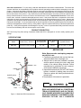
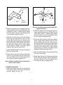
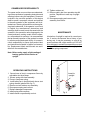
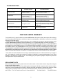
Strut Spring
Compressor
Operating Instruction & Parts Manual
Model Number
Atd-7553
Model Atd-7553
Atd Tools Inc.
114 I-70 Trade Center Drive, St. Peters, MO 63376
Printed in Taiwan
Save these instructions. For your safety, read and understand the information contained within. The owner and
operator shall have an understanding of this product and safe operating procedures before attempting to use this
product. Instructions and Safety information shall be conveyed in the operators native language before use of this
product is authorized. Make certain that the operator thoroughly understands the inherent dangers associated with
the use and misuse of the product. If any doubt exits as to the safe and proper use of this product as outlined in this
factory authorized manual, remove from service until which time it is clear. Inspect before each use. Do not use if
broken, bent, cracked or otherwise damaged parts are noted. If the product has been or suspected to have been
subjected to a shock load, discontinue use until checked out by an authorized factory service center. Owners and
operators of this equipment shall be aware that the use and subsequent repair of this equipment may require special
training and knowledge. It is recommended that an annual inspection be done by qualified personnel and that any
missing or damaged parts, decals, warning / safety labels or signs be replaced with factory authorized replacement
parts only. If this product appears to be damaged in any way, is worn or operated abnormally should be removed
from service immediately until such time as repairs can be made.
PRODUCT DESCRIPTION
Atd Tools Heavy Duty Strut Spring Compressor Model Atd-7553 is designed as an aid in safely replacing strut
springs.
SPECIFICATIONS
Model
Product Size ( L X W X H )
Atd-7553
12 1/4" X 11 7/8" X 52 5/8"
Recommended
Strut Spring Dia.
4" ~ 10"
Max. Working
Space
Hydraulic Stroke
15 1/2"
10" (14 ¼ Max. ~ 4 ¼ Min.)
BEFORE USE
Note: Never service strut spring compressor while in use.
1. Familiarize yourself with this tool and the hazards associated with its improper use.
2. Always refer to and have available a credible
service manual covering the year, make and
model of the vehicle being serviced. Follow
manufacturer's guidelines for strut removal,
service and installation procedures.
3. Inspect before each use. DO NOT USE if bent,
broken, cracked or leaking parts are noted.
Repair or replace with factory authorized components only.
4. No alteration of this device is permitted.
upright
ram
release valve
knob
hydraulic pump
handle
oil plug
base
READ AND UNDERSTAND ALL PRINTED MATERIALS PROVIDED WITH AND ON THIS DEVICE. ENSURE WORKPIECE IS COMPATIBLE
WITH AND IS SECURELY FASTENDED IN COMPRESSOR FIXTURE. ONLY COMPRESS
Figure 1 - Model Atd-7553 Nomenclature
2
SPRING SUFFICIENTLY TO REMOVE RETAINING NUT AND HARDWARE. KEEP FEET AND
HANDS FROM LOADING AREA. NEVER LEAVE
LOADED SPRING COMPRESSOR UNATTENDED. ENSURE THE USER IS THOROUGHLY FAMILIAR WITH THE CONTROLS
AND OPERATIONAL CHARACTERISTICS OF
THIS PRODUCT AND IS AWARE OF THE POTENTIAL HAZARDS ASSOCIATED WITH ITS
USE. ALWAYS WEAR SAFETY GLASSES
WHEN USING. USE ONLY ON HARD LEVEL
SURFACES. DO NOT USE THIS DEVICE FOR
ANY PURPOSE OTHER THAN THAT FOR
WHICH IT IS INTENDED. FAILURE TO HEED
THESE WARNINGS MAY RESULT IN FATAL
INJURY AND/OR PROPERTY DAMAGE.
3. Slide Strut Spring Channel (#18) onto Upright.
Attach Spring Clasp Bracket (#22) to Strut
Spring Channel and secure in horizontal position with Bolt (#8). Attach Spring Clasp Holder
(#23) to Bracket using Wing Nuts (#19), Washers (#30) and Springs (#21). Attach Spring
Clasps (#24) to Holders using Bolts (#25),
Washers (#30) and Wing Nuts (#19).
4. Attach Ram Bracket (#3) to Upright using 2 Bolts
(#31) and 2 Nuts (#32).
5. Attach Upper Wall Bracket (#11) to top of Upright using 2 Bolts (#12).
6. Attach Ram Plunger (#1) to Bracket using Ram
Position Pin (#6), Washer (#9) and Spring Clip
(#4). Insert Ram Piston into Strut Spring Channel (#18) and tighten using Bolt (#17).
NOTE: WALL MOUNT IS NOT FOR USE ON
WOODEN STUDS, SHEET ROCK OR SIMILAR
MATERIALS.
Note: Hardware needed to secure product to
wall is not included.
ASSEMBLY
(please refer fig. 7 on page 7)
B. For bench or floor mount
1. Attach Lower Wall Brackets (#14 & #16) to Upright (#13) using 4 Bolts (#15), 8 Washers (#20)
and 4 Nuts (#26), please refer fig. 3 (for bench)
or fig. 4 (for floor).
A. For beam mount
1. Attach Lower Wall Brackets (#14 & #16) to Upright (#13) using 4 Bolts (#15), 8 Washers (#20)
and 4 Nuts (#26). Please refer fig. 2.
Note: Bench table must be minimum 3/4"
thickness if hardwood or pressboard
is used.
connect to base
(1st & 3rd hole)
connect to
wall
connect to base
(1st & 3rd hole)
left lower
wall bracket
Fig. 2
2. Slide Strut Support (#7) onto Upright. Secure in
lowest possible position using 2 Bolts (#31) and
2 Nuts (#32). Attach "L" Bracket (#29), Adjustable Strut Shaft Clasp (#10) and Washer (#28)
to Strut Support using Knob (#27).
left lower
wall bracket
connect to bench
Fig. 3
3
connect to base
(2nd & 3rd hole)
Fig. 4
left lower
wall bracket
Fig. 5
Note: Do not attach lower wall brackets with
support leg option.
2. Slide Strut Support (#7) onto Upright. Secure in
lowest possible position using 2 Bolts (#31) and
2 Nuts (#32). Attach "L" Bracket (#29), Adjustable Strut Shaft Clasp (#10) and Washer (#28)
to Strut Support using Knob (#27).
2. Slide Strut Support (#7) onto Upright. Secure in
lowest possible position using 2 Bolts (#31) and
2 Nuts (#32). Attach "L" Bracket (#29), Adjustable Strut Shaft Clasp (#10) and Washer (#28)
to Strut Support using Knob (#27).
3. Slide Strut Spring Channel (#18) onto Upright.
Attach Spring Clasp Bracket (#22) to Strut
Spring Channel and secure in horizontal position with Bolt (#8). Attach Spring Clasp Holder
(#23) to Bracket using Wing Nuts (#19), Washers (#30) and Springs (#21). Attach Spring
Clasps (#24) to Holders using Bolts (#25),
Washers (#30) and Wing Nuts (#19).
4. Attach Ram Bracket (#3) to Upright using 2 Bolts
(#31) and 2 Nuts (#32).
4. Attach Ram Bracket (#3) to Upright using 2 Bolts
(#31) and 2 Nuts (#32).
5. Attach Ram Plunger (#1) to Bracket using Ram
Position Pin (#6), Washer (#9) and Spring Clip
(#4). Insert Ram Piston into Strut Spring Channel (#18) and tighten using Bolt (#17).
5. Attach Ram Plunger (#1) to Bracket using Ram
Position Pin (#6), Washer (#9) and Spring Clip
(#4). Insert Ram Piston into Strut Spring Channel (#18) and tighten using Bolt (#17).
Note: Hardware needed to secure product to
beam is not included.
C. Support leg option
1. Attach each Support Leg (#37) to Upright (#13)
using 4 Bolts (#40), 4 Nuts (#41) and 8 Washers (#42), please refer fig. 5 & 7.
4
OWNER/USER RESPONSIBILITY
10. Tighten retainer nut.
11. Remove safety bar from operation step #4
position. Reposition to near top of upright
channel.
12. Decompress spring and remove strut
assembly from fixture.
The owner and/or user must have an understanding of the manufacturer's operating instructions and
warnings before using this equipment. Personnel
involved in the use and operation of this device
shall be careful, competent, trained, and qualified
in the safe operation of the equipment and its intended use. Warning information must be emphasized and understood. If the operator is not fluent
in English, the manufacturer's instructions and
warnings shall be read to and discussed with the
operator in the operator's native language by the
owner/purchaser, making certain that the operator comprehends its contents. It is recommended
that an annual inspection of the product be made
by a factory authorized repair facility. It is owner's/
user's responsibility to ensure that product label
and instructional material is legible and accessible. Replacement labels and manuals are available from the manufacturer.
MAINTENANCE
Lubrication of upright is required in normal service. If service environment has a history of producing rust, it may be necessary to coat all exposed surfaces with a light machine oil. DO NOT
allow lubricant to contact claw assemblies nor strut
springs. IF SO, clean and dry thoroughly before
use in the spring compressor.
Note: Before using, apply a light coating of
bearing grease to mid-section of
upright.
OPERATING INSTRUCTIONS
insert to
upright
1. Secure base of strut in compressor fixture by
adjustable strut shaft clasp.
2. Secure spring with claw assembly.
3. Pump to compress spring.
4. Install safety bar in upright directly above strut
spring channel (please refer fig. 6 ).
5. Remove nut and retainer cup assembly.
6. Decompress spring and remove.
7. Replace damaged components.
8. Install spring and compress.
9. Install retainer cup assembly and nut.
Fig. 6
5
TROUBLESHOOTING
Symptom
Possible Causes
Corrective Action
Ram will not extend
Release valve not tightly closed
Overload condition
Ensure release valve tightly closed
Remedy overload condition
Ram bleeds off
Release valve not tightly closed
Overload condition
Hydraulic unit malfunction
Ensure release valve tightly closed
Remedy overload condition
Contact Atd Tools Tech. Service
Reservoir overfilled
Ram will not retract after unloading Linkages binding
Drain fluid to proper level
Clean and lubricate moving parts
Ensure proper fluid level
With ram fully retracted, remove oil filler
plug to let pressurized air escape, reinstall
oil filler plug
Fluid level low
Poor performance
Air trapped in system
Will not extend to full extension
Ensure proper fluid level
Fluid level low
ONE YEAR LIMITED WARRANTY
For a period of one (1) year from date of purchase, Atd Tools Inc. will repair or replace, at its option, without charge,
any of its products which fails due to a defect in material or workmanship, or which fails to conform to any implied
warranty not excluded hereby.
Performance of any obligation under this warranty may be obtained by returning the warranted product, freight
prepaid, to Atd Tools Inc. Warranty Service Department, 114 I-70 Trade Center Drive, St. Peters, MO 63376.
Except where such limitations and exclusions are specifically prohibited by applicable law. (1) the CONSUMER'S
SOLE AND EXCLUSIVE REMEDY SHALL BE THE REPAIR OR REPLACEMENT OF DEFECTIVE PRODUCTS AS
DESCRIBED ABOVE, and (2) Atd Tools Inc. SHALL NOT BE LIABLE FOR ANY CONSEQUENTIAL OR INCIDENTAL DAMAGE OR LOSS WHATSOEVER, and (3) THE DURATION OF ANY AND ALL EXPRESSED AND IMPLIED
WARRANTIES, INCLUDING WITHOUT LIMITATION, ANY WARRANTIES OF MERCHANTABILITY AND FITNESS
FOR A PARTICULAR PURPOSE, IS LIMITED TO A PERIOD OF ONE (1) YEAR FROM DATE OF PURCHASE.
Some states do not allow limitations on how long an implied warranty lasts, so the above limitation may not apply to
you. Some states do not allow the exclusion or limitation of incidental or consequential damages, so the above
limitation or exclusion may not apply to you. This warranty gives you specific legal rights, and you may also have
other rights which vary from state to state.
REPLACEMENT PARTS
When ordering replacement parts, please refer to the model number / serial number found on the product, then give
the part number and description.
Available Parts: Please refer to the Parts drawing when ordering parts. Not all components of the jack are replacement items, but are illustrated as a convenient reference of location and position in the assembly sequence. When
ordering parts, give Model number, serial number and description below. Call or write for current pricing:
Atd Tools Inc. 114 I-70 Trade Center Drive, St. Peters, MO 63376
Tel:(636)272-9050
Fax:(636)272-9044
6
Model Atd-7553
Parts No.
Description
Quantity
1
2
3
4
5
6
7
8
9
10
11
12
13
14
15
16
17
18
19
20
21
ram plunger
hydraulic pump
ram bracket
spring clip
bracket pin D15.8 x 96
ram position pin D10 x 76
strut support
bolt M10 x 1.5 x 10L
washer D20 x D10.4 x 1.2
adjustable strut shaft clasp
wall bracket - upper
bolt M10 x 1.5 x 16L
upright
wall bracket - lower left
bolt 1/2" - 12UNC x 1 1/4"
wall bracket - lower right
bolt - M8 x 1.25P x 15L
strut spring channel
wing nut 1/2" - 12 UNC
washer D24 x D13 x 2.5T
spring D18 x D2 x D15
1
1
1
2
1
1
1
1
1
1
1
2
1
1
4
1
1
1
4
8
2
Parts No.
Description
22
23
24
25
26
27
28
29
30
31
32
36
37
38
39
40
41
42
43
44
spring clasp bracket
spring clasp holder
sping clasp / claw
screw 1/2" - 12 UNC x 1/2"
nut W1/2 x 12 UNC
knob
washer D31 x D16.2 x 4T
" L " Bracket
washer D30 x D13 x 5T
bolt - M16 x P2 x 90L
nut - M16 x P2
leg assy. ( for option only)
support leg
swivel wheel assy.
swivel wheel assy.
bolt
nut - nylon
washer
label(s) (not shown)
manual (OIPM# 90000-01)
Figure 7 - Replacement Parts Illustration for Model Atd-7553
7
Quantity
1
2
2
2
4
1
1
1
6
4
4
1
2
2
2
4
4
8
1
1
Atd Tools Inc.
114 I-70 Trade Center Drive St. Peters, MO 63376
Tel: (636)272-9050 Fax: (636)272-9044