1
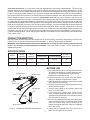
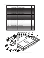
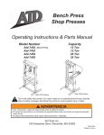
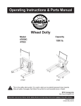
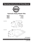
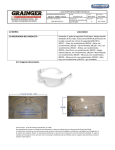
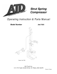
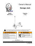
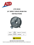
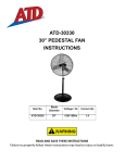
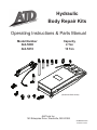
Hydraulic Body Repair Kits Operating Instructions & Parts Manual Model Number Atd-5800 Atd-5810 Capacity 4 Ton 10 Ton (Model Atd-5810 shown) Atd Tools Inc. 160 Enterprise Drive, Wentzville, MO 63385 OIPM#5800-0309 Printed in China Save these instructions. For your safety, read and understand the information contained within. The owner and operator shall have an understanding of this product and safe operating procedures before attempting to use this product. Instructions and Safety information shall be conveyed in the operators native language before use of this product is authorized. Make certain that the operator thoroughly understands the inherent dangers associated with the use and misuse of the product. If any doubt exists as to the safe and proper use of this product as outlined in this factory authorized manual, remove from service. Inspect before each use. Do not use if broken, bent, cracked or otherwise damaged parts are noted. If any component of this product has been or suspected to have been subjected to a shock load (a load dropped suddenly, unexpectedly upon it), discontinue use until checked out by an Atd Tools authorized service center. Owners and operators of this equipment shall be aware that the use and subsequent repair of this equipment may require special training and knowledge. It is recommended that an annual inspection be done by qualified personnel and that any missing or damaged parts, decals, warning / safety labels or signs be replaced with factory authorized replacement parts only. Any component of this Body Repair Kit that appears to be damaged in any way, is worn or operates abnormally shall be removed from service immediately until such time as it can be repaired/replaced. Labels and Operator's Manuals are available from the manufacturer (see Replacement Parts, pages 7 & 8). PRODUCT DESCRIPTION Atd Tools Hydraulic Body Repair Kits are designed to be used for pushing, spreading, and pressing of vehicle body panels as well as various component parts and assemblies. A variety of attachments are included. WARNING: when extension tubes and/or offset attachments are used, the rated capacity is always reduced by 50 % for each tube or offset attachment connected. See Parts Section on page 7 & 8 for identification of "offset" attachments. SPECIFICATIONS Ram Model Pump Capacity Ram Capacity Closed Height Extended Height Number of Attachments Atd-5800 8,000 psi 4 Ton 10-3/4” 15-5/8” 14 Atd-5810 10,000 psi 10 Ton 13-3/4” 19-3/4” 13 BEFORE USE pump handle release valve oil filler screw ram plunger hose dust cover ram coupler hose coupler Figure 1 - Atd-5800 and Atd-5810 Nomenclature 2 1. Before using this product, read the owner's manual completely and familiarize yourself thoroughly with the product, its components and recognize the hazards associated with its use. 2. Inspect before each use. Do not use if bent, broken, leaking or damaged components are noted. 3. Check to ensure that all parts of your kit are included (see illustration and parts list). 4. Carefully remove the dust caps and plugs from hose coupler and ram coupler. 5. Connect hose coupler to ram coupler, ensure that there are no fluid leaks. 6. Locate and open release valve. Close release valve clockwise and pump handle until ram is fully extended, then open release valve counter-clockwise until ram has fully retracted. 7. With ram fully retracted and release valve open, place pump in horizontal position. Locate and open oil filler screw (on reservoir body, near the back). This will release air trapped within the reservoir. Retighten the oil filler screw. 8. If using with air actuated units, an air source of at least 7.8 CFM @ 90 PSI is required. GENERAL SAFETY INFORMATION 1. Ensure that attachments are fully engaged before applying load. 2. Ensure that load is centrally applied to attachment or ram saddle. Do not load off center. 3. Always monitor the force applied to workpiece by using a load cell and indicator or you may monitor pressure developed in the ram by using an inline pressure gauge, then calculate the applied force using the formula: F = P x A, where F = lbs force, P = pressure in PSI, and A = effective ram area in in2. Ram Area of Model 50040 is: 0.998 in2 Ram Area of Model 50100 is: 2.411 in2 You can refer to Load-Pressure correlation chart on page 9. 4. If bowing or bending of ram or any attachment occurs during use, "STOP", release pressure immediately and reconsider application. Application may not be compatible with product, a ram kit with a higher capacity may be needed. ! DANGER • If oil leakage is detected, discontinue use of the ram immediately and contact your nearest Omega authorized Service Center. The ram could develop excessive pressure and cause the ram, hose or coupler to burst, which could cause serious injury or death. ! WARNING To avoid crushing and related injuries: NEVER work on, under or around a lifted load before it is properly supported by appropriate mechanical means such as jack stands. Never rely on hydraulic pressure alone to support load. OPERATION Wear protective clothing and safety goggles to reduce the risk of injection. Note: Inspect before each use for evidence of fluid leaks, damaged hydraulic fittings, bent or broken attachments and missing parts. 1. Locate and close release valve by turning it clockwise until firmly closed. (Do not over tighten) 2. Operate by pumping handle. This will send fluid from the pump reservoir into the high pressure hose assembly and into the ram assembly. 3. Continue pumping until ram reaches desired position. ! WARNING • All WARNING statements must be carefully observed to help prevent personal injury. • Do not exceed rated capacity. • Use only on hard, level surfaces capable of sustaining rated capacity loads. • Do not open oil filler screw unless ram is fully retracted. • Do not wear sandals and jewelry when operating this equipment. • Do not use as a vehicle lifting device or vehicle support. • Any attachment that is not loaded centrally, as through the centerline of the ram, is considered to be “offset”. • When extension tubes and/or offset attachments are used, the rated capacity is always reduced by 50% for each tube or attacment connected. • Monitor pressure and load at all times. • Always verify load with calibrated load cell and indicator, known good pressure gauge or equivalent devices. • Do not modify this device. • Failure to heed these markings may result in personal injury and/or property damage. Note: Pump may be used in horizontal and vertical position as illustrated (See figure. 2). Figure 2 - Horizontal and Vertical position To Release Pressure on work piece: Slowly, carefully turn the release valve counterclockwise until ram retracts to desired position. Never turn release valve more than 1/2 of a full turn. The ram return system is spring loaded and the release valve system is metered, allowing controlled retraction of the ram. 3 ! WARNING ! WARNING • Avoid pinch points or crush points that can be created by the load or parts of ram. • To help prevent material fatigue if the ram is to be used in a continuous application, the load should not exceed 85% of the rated capacity. • Ram must be on a stable base which is able to support the load while pushing or lifting. • Ensure ram is fully engaged into/onto adapters, extension accessories. • To help prevent personal injury, use shims, friction material or constraints to prevent slippage of the base or load. • Do not off-center loads on a ram. The load can tip or the ram can “kick out” and cause personal injury. Hydraulic Hoses and Fluid Transmission Lines • Avoid short runs of straight line tubing. Straight line runs do not provide for expansion and contraction due to pressure and/or temperature changes. • Reduce stress in tube lines. Long tubing runs should be supported by brackets or clips. Before operating the pump, all hose connections must be tightened with the proper tools. Do not overtighten. Connections should only be tightened securely and leak-free. Overtightening can cause premature thread failure or high pressure fittings to burst. • Should a hydraulic hose ever rupture, burst or need to be disconnected, immediately shut off the pump and release all pressure. Never attempt to grasp a leaking pressurized hose with your hands. The force of escaping hydraulic fluid can inflict injury. • Do not subject the hose to potential hazard such as fire, sharp objects, extreme heat or cold, or heavy impact. • Do not allow the hose to kink, twist, curl, crush, cut or bend so tightly that the fluid flow within the hose is blocked or reduced. Periodically inspect the hose for wear, because any of these conditions can damage the hose and possibly result in personal injury. • Do not pull, position or move setup by the hose. Doing so can damage the hose and possibly cause personal injury. • Hose material and coupler seals must be compatible with hydraulic fluid used. Hoses also must not come in contact with corrosive materials such as battery acid, creosote-impregnated objects and wet paint. Hose deterioration due to corrosive material can result in personal injury. Never paint a coupler or hose. • The user must be a qualified operator familiar with the correct operation, maintenance, and use of rams. Lack of knowledge in any of these areas can lead to personal injury. • Use only approved accessories and approved hydraulic fluid. • Do not exceed the rated capacity of the ram. • Inspect each ram and coupler before each use to prevent unsafe conditions from developing. • Do not use rams if they are damaged, altered or in poor condition. • Do not use rams with bent or damaged coupler or damaged threads. • Under certain conditions, the use of an extension with a hydraulic ram may not be advisable and could present a dangerous condition. Center loads on ram • As the load is lifted, use blocking and cribbing to guard against a falling load. • Never allow personnel to work on, under or around a load before it is properly supported by appropriate mechanical means. Never rely on hydraulic pressure alone to support load. • All personnel must be clear before lowering. • Never try to disassemble a hydraulic cylinder, Refer repairs to qualified, authorized personnel. IMPORTANT • Keep ram clean at all times. • When the ram is not is use, keep the piston(s) fully retracted. • Use an approved, high-grade pipe thread sealant to seal all hydraulic connections. Teflon tape can be used if only one layer of tape is used and it is applied carefully (two threads back) to prevent the tape from being introduced into hydraulic system. A piece of tape could travel through the system and obstruct the flow of fluid and adversely affect function. • Never attach ANY component not authorized by manufacturer. • Never use other than factory provided and/or authorized fasteners. KNOW YOUR SYSTEM Your ram, hose(s), couplings and pump all must be rated for the same maximum operating pressure, correctly connected and compatible with the hydraulic fluid used. An improperly matched system can cause the system to fail and possibly cause serious injury. If you are in doubt, consult your nearest Atd Tools Dealer. 4 Basic Setup The capacity of the body repair kit can be significantly affected by the number of attachments used and the type of load applied. The approximate load capacity of each function setup is illustrated below. When two or more extension tubes are used together, be sure to position the shortest tube further away from the ram. A. Push Serrated Saddle 100% Ram Flat Base Male Connector Ram Rubber Head Male Connector 100% Flat Base (ii) Horizontal Push (i) Vertical Push Flat Base Extension Tube Male Connector Ram Combination Head (900) 25% (iii) Horizontal Push with Extension B. Spread Ram 25% Ram Ram Toe 0.5 Ton Plunger Toe Ram Toe Hydraulic Spreader Extension Tube 25% Flat Base (i) Vertical Spread (ii) Horizontal Spread MAINTENANCE (iii) Hydraulic Spreader Changing oil For best performance and increased system life, replace the complete fluid supply at least once per year. Important: Use only a good grade hydraulic jack oil. Avoid mixing different types of fluid and Never use brake fluid, turbine oil, transmission fluid, motor oil or glycerin. Improper fluid can cause premature failure of the ram and the potential for sudden and immediate loss of load. We recommend Mobil DTE 13M or equivalent. 1. With ram fully lowered, remove the oil filler screw from the pump reservoir as above. 2. Lay the pump on its side and drain the fluid into a suitable container. Adding oil 1. With ram fully lowered, set pump unit in its normal, level position. Locate and remove oil filler screw. 2. Fill until oil is within 3/8" of the oil filler screw hole opening, re-install oil filler screw. Note: Dispose of hydraulic fluid in accordance with local regulations. 3. Set pump in its level upright position. 4. Fill with good quality jack oil to within 3/8" of the oil filler screw hole opening. Reinstall oil filler screw. 5 Note: Never use sandpaper or abrasive material on these surfaces! Lubrication A coating of light lubricating oil to pivot points and hinges will help to prevent rust and assure that pump assemblies move freely. Storage When not in use, store with the pump piston and ram fully retracted. Cleaning Periodically check the pump piston and ram for signs of rust or corrosion. Clean as needed and wipe with an oily cloth. TROUBLESHOOTING GUIDE The following information is intended as an aid in determining if problem exists. For repair service, contact Atd Tools service center in your area. Possible Causes Symptom Corrective Action Ram will not extend, or respond to pressurized fluid • Overload condition. • Release valve not closed. • Remedy overload condition. • Ensure release valve closed. Ram responds to pressurized fluid, but system does not maintain pressure • Overload condition. • Release valve not closed. • Hydraulic unit malfunction. • Remedy overload condition. • Ensure release valve closed. • Contact Service Center. Ram will not return fluid to pump • Malfunctioning coupler, damaged application. • Secure load by other means. Open release valve, depressurize pump and hose, remove application and replace coupler. • Secure load by other means. Open release valve, depressurize pump and hose, remove application, then drain fluid to proper level. • Reservoir overfilled. Ram will not fully extend (cylinder or spreader) • Fluid level low. • Secure load by other means. Open release valve, depressurize pump and hose, remove application, then add fluid to proper level. Poor performance • Fluid level low. • Air trapped in system. • Ensure proper fluid level. • Vent the sytem (refer to figure 3) How to bleed air from system 1. Bleed air from ram: Place pump at a higher elevation than the hose and ram as shown in figure 3 below. The objective is to “float the air bubbles up hill and back to the reservoir where they belong. Close valve and extend ram as fas as possible. Open valve fully allowing oil and air to return to reservoir. Repeat this procedure two or three times will do the trick. 2. Bleed air from pump: With ram fully retracted, remove oil filler screw to let pressurized air escape, then reinstall oil filler screw. Figure 3 - Pump and ram illustration to bleed air 6 Model No. Atd-5800 Ref No. 1 2 3 4 5 6 7 8 9 10 11 12 13 14 15 16 17 18 19 20 21 22 23 24 25 - Part# F040-41500-000 F040-41100-000 F040-41200-000 F040-41300-000 F040-41400-000 F040-41600-000 F040-40001-000 F040-40003-000 F040-44000-000 F040-40005-000 F040-40004-000 F040-43000-000 F040-40002-000 F040-71000-000 F040-50001-000 F040-30007-001 F040-90037-K02 F040-90037-K01 F040-60000-000 F040-21000-000 F040-90009-K03 F040-51000-000 F040-90107-K02 F040-50000-000 F040-00001-000 Atd-5800-L0 5800-0309 Description Extension Tube (19-1/2") Extension Tube (16-1/2") Extension Tube (8-1/2") Extension Tube (6-1/8") Extension Tube (3") Male connector Wedge Head Serrated Saddle Flat Base Plunger Toe Ram Toe Rubber Head Combination Head Hydraulic Spreader (1000 lb. capacity) Dust Cover - Hose Dust Cover - Ram Hose Coupler, Male Ram Coupler Assy, Female Ram Assembly Release Valve Knob Pump Handle Hose Assembly (with coupler) Oil Filler Screw Pump Assembly Blow Molded Case Label (not shown) Manual Figure 3 - Replacement Parts Illustration for Model Atd-5800 7 Qty 1 1 1 1 1 1 1 1 1 1 1 1 1 1 1 1 1 1 1 1 1 1 1 1 1 1 1 Model No. Atd-5810 Ref No 1 2 3 4 5 6 7 8 9 10 11 12 13 14 15 16 17 18 19 20 21 22 23 24 - Part# F100-41100-000 F100-41200-000 F100-41300-000 F100-41400-000 F100-41500-000 F100-40002-000 F100-40004-000 F100-40001-000 F100-40006-000 F100-40005-100 F100-42000-100 F100-40003-000 F040-71000-000 F040-50001-000 F040-30007-001 F040-90037-K02 F040-90037-K01 F100-60000-000 F040-21000-000 F100-90009-K01 F040-51000-000 F040-90107-K02 F100-50000-000 F100-00001-000 Atd-5810-L0 5800-0309 Description Extension Tube (27") Extension Tube (18") Extension Tube (10") Extension Tube (4") Male Connector Wedge Head (offset) Serrated Saddle Flat Base Plunger Toe (offset) Ram Toe (offset) Rubber Head Combination Head (90o) Hydraulic Spreader (1000 lb. capacity) Dust Cover - Hose Dust Cover - Ram Hose Coupler, Male Ram Coupler Assy., Female Ram Assembly Release Valve Knob Pump Handle Hose Assembly Oil Filler Screw Pump Assembly Blow Molded Case Label ( not shown) Manual Figure 4 - Replacement Parts Illustration for Model Atd-5810 8 Qty 1 1 1 1 1 1 1 1 1 1 1 1 1 1 1 1 1 1 1 1 1 1 1 1 1 1 Load - Pressure Correlation For Model Atd-5800 & Atd-5810 Always monitor the force applied to workpiece by using a load cell and indicator or you may monitor pressure developed in the ram by using an inline pressure gauge, then calculate the applied force using the formula: F=PxA where F = Force/ Load (lbs); P = Hydraulic working pressure (psi) and; A = Ram effective area (in²) For model Atd-5800, A = 0.998 in² ; For model Atd-5810, A = 2.411 in² Example1 Model Atd-5800 lifting 5,000 lbs will require what presure? Pressure = 5,000 lbs 0.998 in² = 5,010 psi Example2 Model Atd-5810 operating at 6,000 psi will generate what force? Force = 6,000 psi x 2.411 in2 = 14,466 lbs Load (lbs) 1,000 2,000 3,000 4,000 5,000 6,000 7,000 8,000 9,000 10,000 11,000 12,000 13,000 14,000 15,000 16,000 17,000 18,000 19,000 20,000 Pressure of 4 Ton Ram, where A = 0.998 in2 (psi) 1,002 2,004 3,006 4,008 5,010 6,012 7,014 8,016 9 Pressure of 10 Ton Ram, where A = 2.411 in2 (psi) 415 830 1,244 1,659 2,074 2,489 2,903 3,318 3,733 4,148 4,562 4,977 5,392 5,807 6,221 6,636 7,051 7,466 7,881 8,295 REPLACEMENT PARTS Available Parts: Please refer to the Parts drawing when ordering parts. Not all components of this kit are replacement items, but are illustrated as a convenient reference of location and position in the assembly sequence. When ordering parts, give Model number, serial number and description below. Call or write for current pricing: Atd Tools Inc. 160 Enterprise Drive, Wentzville, MO 63385 Tel:(636)327-9050 Fax:(636)327-9046 ONE YEAR LIMITED WARRANTY For a period of one (1) year from date of purchase, Atd Tools Inc. will repair or replace, at its option, without charge, any of its products which fails due to a defect in material or workmanship, or which fails to conform to any implied warranty not excluded hereby. Performance of any obligation under this warranty may be obtained by returning the warranted product, freight prepaid, to Atd Tools Inc. Warranty Service Department, 160 Enterprise Drive, Wentzville, MO 63385. Except where such limitations and exclusions are specifically prohibited by applicable law, (1) the CONSUMER'S SOLE AND EXCLUSIVE REMEDY SHALL BE THE REPAIR OR REPLACEMENT OF DEFECTIVE PRODUCTS AS DESCRIBED ABOVE, and (2) Atd Tools Inc. SHALL NOT BE LIABLE FOR ANY CONSEQUENTIAL OR INCIDENTAL DAMAGE OR LOSS WHATSOEVER, and (3) THE DURATION OF ANY AND ALL EXPRESSED AND IMPLIED WARRANTIES, INCLUDING WITHOUT LIMITATION, ANY WARRANTIES OF MERCHANTABILITY AND FITNESS FOR A PARTICULAR PURPOSE, IS LIMITED TO A PERIOD OF ONE (1) YEAR FROM DATE OF PURCHASE. Some states do not allow limitations on how long an implied warranty lasts, so the above limitation may not apply to you. Some states do not allow the exclusion or limitation of incidental or consequential damages, so the above limitation or exclusion may not apply to you. This warranty gives you specific legal rights, and you may also have other rights which vary from state to state. Atd Tools Inc. 160 Enterprise Drive, Wentzville, MO 63385 Tel: (636)327-9050 Fax: (636)327-9046 www.atdtools.com 10 Notes Atd Tools Inc. 160 Enterprise Drive, Wentzville, MO 63385 Tel: (636)327-9050 Fax: (636)327-9046 www.atdtools.com Notes Atd Tools Inc. 160 Enterprise Drive, Wentzville, MO 63385 Tel: (636)327-9050 Fax: (636)327-9046 www.atdtools.com