1
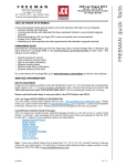
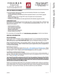
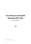
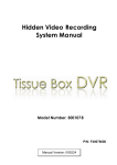
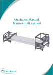
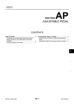
GENUINE PARTS
INSTALLATION INSTRUCTIONS
DESCRIPTION:
APPLICATION:
PART NUMBER:
KIT CONTENTS:
Item
A
B
C
D
E
F
G
H
I
J
K
L
M
QTY
1
1
1
1
1
1
1
14
1
1
2
1
1
LED Daytime Driving Lights
MURANO,MURANO CROSS CABRIOLET
LED Daytime Driving Lights(B66M0 1AA0B)
Description
Lamp Module RH
Lamp Module LH
Control Unit
Unit Bracket
Accessory Engine Room Harness
Accessory Main Harness
Accessory Lamp Harness
Tie Wrap (L=150mm)
M6 Bolt
M6 Nut
Tape
Butyl Tape
Installation Instruction Replacement Template
A
H
5.
B
I
C
J
D
K
E
L
Service Part Number
B6600 1AA00
-----------------------
F
G
M
TOOLS REQUIRED:
● Nylon removal tool
● Wire cutter
● 10mm Socket and driver
● Phillips screw driver
● Masking tape
● Flash light
● Scissors
● 100% alcohol
● Soap water
● Soft non linting towel
● Awl
● Metric ruler (200mm)
Page 1 of 13
B66M0 1AA0B II Rev. 10/22/2013
PRE-INSTALLATION CAUTIONS/NOTES
CAUTION
● Dealer Installation Recommended. Instructions refer to Service Manual.
● Please read this instruction carefully before installing this product for correct installation.
● Please DO NOT use or install the part in ways other than what is described in this instruction
manual.
● If problem occurs during installation, please contact Nissan dealer where you purchased
the product.
● Pay attention when removing trim parts to avoid breaking clips.
1)Apply Parking Brake.
2)Make sure the shift lever is engaged in"P"or"N"position.
Preset
A
B
C
3)Record customer Radio Presets.
4)Use seat and floor protection.
5)Open the hood of the vehicle.
1
2
3
4
5
6
6)Disconnect the negative battery terminal to prevent short circuits during installation.
7)This part is to be installed at a vehicle body surface temperature of 65-100°F.
8)Do not wash the vehicle for 24 hours after installing to prevent the double-sided tape from peeling.
CAUTION
●Care must be taken not to scratch or damage any components during the removal or
replacement process.
9)Remove the following vehicle parts in the sequence shown below.
1
2
7
6
5
8
1.Radiator core support cover LH/RH
2.Front bumper grille
3.Headlamp extension panel LH/RH
4.Splash guard LH
5.Fender protector LH
6.IPDM module cover
7.IPDM module cover FR
8.Wheel and tire LH
3
4
9.Instrument side finisher LH
10.Instrument lower panel (driver)
11.Front kicking LH
12.Dashboard Side Lower panel LH
13.Fuse box
9
10
13
12
11
Page 2 of 13
B66M0 1AA0B II Rev. 10/22/2013
INSTALLATION OVERVIEW:
STANDARD CONNECTION METHOD
IPDM
Connector of vehicle IPDM
Page 3 of 13
B66M0 1AA0B II Rev. 10/22/2013
INSTALLATION PROCEDURE:
Radiator core support
Fig 1
VEHICLE PARTS REMOVAL
1) Radiator core support cover (LH/RH) removal
Disengage the clips (15 places),and
then remove the Radiator core support
cover LH/RH.
2) Front bmpr grille removal
Disengage the clips (6 places),and
then remove the Front bumper grille.
Shown in Fig 1.
: Pawl
Front bumper grille
Fig 2
Screw
3) Headlamp extension panel (LH/RH) removal
Remove the screws (RH and LH)
connecting the front surface of bumper.
Remove the Headlamp extension
panel (LH/RH).
Shown in Fig 2.
: Pawl
Headlamp extension panel
Fig 3
4) Wheel (LH) removal
Remove the wheel (LH) from the
vehicle.
Shown in Fig 3.
Wheel and tire
Fender protecter LH
Fig 4
5) Splash guard (LH) removal
Remove the clips (4 places) connecting
the splash guard (LH).
6) Fender protector (LH) removal
Remove the screws (9 places) and
clips (4 places) connecting the
fender protector (LH).
Shown in Fig 4.
FR
Splash guard LH
Page 4 of 13
B66M0 1AA0B II Rev. 10/22/2013
INSTALLATION PROCEDURE:
IPDM module cover
Fig 5
7) IPDM module cover removal
Push pawls and lift up the rear side of
IPDM module cover.
8) IPDM module cover FR removal
Push pawls and lift up the IPDM
module cover.
Shown in Fig 5.
:Pawl
IPDM module cover FR
Instrument side finisher LH
Fig 6
9) Instrument side finisher (LH) removal
Detach Instrument Side Finisher LH
mounting clips with nylon removal tool
and remove Instrument Side Finisher LH.
Shown in Fig 6.
Nylon
removal
tool
:Pawl
Instrument lower panel (LH)
Fig 7
10) Instrument lower panel (driver) removal
a) Remove hood opener mounting screw
then remove hood opener.
b) Pull downward on instrument lower
panel (LH) to disengage pawls and
clips .
c) Disconnect harness from instrument
lower panel (LH).
Shown in Fig 7.
Hood opener
Screw
Page 5 of 13
B66M0 1AA0B II Rev. 10/22/2013
INSTALLATION PROCEDURE:
Fig 8
11) Front kick plate inner (LH) removal
Pull up on front kick plate inner to
disengage pawls.
Shown in Fig 8.
Front kick plate inner(LH)
:Pawl
:Metal clip
Fig 9
12) Dash side finisher (LH) removal
Pull dash side finisher (LH) to
disengage mounting clips (2 places).
Shown in Fig 9.
Dash side finisher(LH)
Clip
Fuse box
Fig 10
Screw
13) Fuse box removal
a) Remove the mounting screws (2) from
the fuse box.
b) Disconnect fuse box connectors
(3 places).
Shown in Fig 10.
Fuse box
connector ×3
Screw
Page 6 of 13
B66M0 1AA0B II Rev. 10/22/2013
INSTALLATION PROCEDURE:
Bolt
Bracket
Fig 11
LAMP MODULE INSTALLATION
14) Control Unit installation
a) Attach Control Unit Bracket to
Control Unit as shown in Fig 11.
Nut
Bracket
Control Unit
b) Secure the Control Unit with Bolt
Control Unit
and Nut as shown in Fig 11.
RH
FR
Reinf
Front
Control Unit
Fig 12
Bolt
LH
FR
FR
15) Lamp Module installation
a) Secure the Lamp Module at the
headlamp extension panel position
using previously removed bolt.
Headlamp LH
Lamp Module
RH
Accessory
Lamp Harness
Control Unit
Front bumper
b) Connect the Accessory Lamp
Harness to Control Unit and
Lamp Module Harness (LH/RH) as
shown in Fig 12.
Connector
Page 7 of 13
B66M0 1AA0B II Rev. 10/22/2013
INSTALLATION PROCEDURE:
WIRING HARNESS INSTALLATION
FR
Fig13
RH
Tie Wrap (L=150mm)
Front Bumper
OUTSIDE WIRING HARNESS INSTALLATION
16) Connect the Accessory Engine Room
Harness (LH/RH) to Control Unit Harness
(LH/RH).
17) Secure the Accessory Engine Room
Harness to the vehicle harness with Tie
Wraps (4 places) (L=150mm).
Shown in Fig13
CAUTION
●Do not allow harness to contact moving
parts or vehicle edge.
Control Unit
Connector
Lamp Module LH
Lamp Module RH
Fig14
Female
Terminal
Male
Terminal
8-pin
connector
18) Accessory Engine Room Harness installation
(Inside engine room)
a) Route 2-pin connector line along the
vehicle harness to head lamp LH rear
side as shown in Fig 14.
b) Route 8-pin connector and Female
Terminal along the vehicle harness to
IPDM module as shown in Fig 14.
IPDM module
Accessory
Engine Room
Harness
2-pin
connector
c) Route Male Terminal along the hood
lock cable to inside of front fender (LH)
as shown in Fig 14.
Hood lock
cable
Head lamp LH
Page 8 of 13
B66M0 1AA0B II Rev. 10/22/2013
INSTALLATION PROCEDURE:
Fig15
A
Fig15-a
Accessory Engine Room Harness
Head lamp LH
Tie Wrap (L=150mm)
FR
Front fender
seal(front)
(LH)
Front side marker
lamp connector
19) Accessory Engine Room Harness connection.
a) Pull back Front fender seal (front)
(LH).
Disconnect front side marker lamp
(LH) connector.
Connect 2-pin connector of Accessory
Engine Room Harness to front side
marker lamp (LH) and vehicle side
connector.
Secure the Accessory Engine Room
Harness with Tie Wrap (1 place)
(L=150mm) as shown in Fig 15-a.
Front side marker lamp harness
8-pin connector
Fig15-d
Female terminal
Fig15-b
Connector
lock
IPDM module
Accessory Engine
Room Harness
TH20FW-CS12-M4-1V Fig15-c
b) Disconnect IPDM module connector
(TH20FW-CS12-M4-1V) using lever
and then partially disengage connector
lock as shown in Fig 15-c.
Insert terminal from Accessory Engine
Room Harness into connector of power
supply harness as shown in Fig 15b,c,d and then engage connector lock.
c) Disconnect IPDM module connector.
Connect 8-pin connector of
Accessory Engine Room Harness to
IPDM module and vehicle side
connector.
Shown in Fig15-d
Female
terminal
plug-in
Connector is view from harness side
Page 9 of 13
B66M0 1AA0B II Rev. 10/22/2013
INSTALLATION PROCEDURE:
Tie Wrap (L=150mm)
Fig 16
Tie Wrap
(L=150mm)
20) Secure Accessory Engine Room Harness.
Secure the Accessory Engine Room
Harness to the vehicle harness with Tie
Wraps (L=150mm, 6 places) as shown
in Fig 16.
CAUTION
Accessory
Engine Room
Harness
●Do not secure hood lock wire.
●Do not allow harness to contact moving
parts or vehicle edge.
Hood lock cable
Tie Wrap (L=150mm)
Hood lock cable
Tape
Fig 17
Grommet
21) Accessory Engine Room Harness
installation
a) Route male terminal along the hood
lock cable to grommet as shown
in Fig 17.
b) Pierce a pin hole through grommet
for Accessary Engine Room Harness.
(See next page for instruction.)
22)Secure Accessory Engine Room Harness
Secure the Accessory Engine Room
Harness to hood lock cable with Tape
(2 places) as shown in Fig 17.
Way to cut Tape
Cut the Tape in half
Accessory Engine
Room Harness
Tape
Accessory Engine
Room Harness
Grommet
Tape
Hood lock cable
Tape
CAUTION
●Clean mounting surface with 100%
alcohol
Page 10 of 13
B66M0 1AA0B II Rev. 10/22/2013
INSTALLATION PROCEDURE:
23) Pierce a pin hole with an awl in the hood lock
wire grommet as shown in Fig 18.
Fig 18
CAUTION
Grommet
Awl
●When piercing grommet use caution
and do not cut wire.
Hood lock wire
24) Expand the hole with a Phillips screw driver
as shown in Fig 19.
Fig 19
Plus screw driver
Fig 20
25) Insert the terminal of Accessory Engine
Room Harness through the grommet until
vinyl tubing contacts grommet.
Shown in Fig. 20.
Terminal
Fig 21
10mm
Grommet
Vinyl tube
Corrugate
tube
26) Cut 10mm wide strip of Butyl Tape.
a) Apply Butyl Tape to seal the pierced
hole on the grommet.
b) Clean panel with 100% alcohol and
attach the Tape.
Shown in Fig. 21.
Butyl Tape
Tape
Vinyl tube
Corrugate tube
Page 11 of 13
B66M0 1AA0B II Rev. 10/22/2013
INSTALLATION PROCEDURE:
Fig22-a
Accessory Main Harness
Accessory Engine Room Harness
A
Fig22-b
Tie wrap (L=150mm)
Accessory Main Harness
INSIDE WIRING HARNESS INSTALLATION
27) Accessory Harness connection
Connect plug on the Accessory Main
Harness to the Accessory Engine
Harness as shown in Fig 22-a.
28) Accessory Main Harness installation
Route Accessory Main Harness along
the vehicle harness to PKB switch as
shown in Fig 22-a,b,c.
Disconnect PKB switch connector.
Connect connector of Accessory Main
Harness to PKB switch connector and
vehicle side connector as shown in Fig
22-c.
29) Secure Accessory Engine Room Harness.
Secure the Accessory Main Harness
with Tie Wrap (3 places,L=150mm) as
shown in Fig 22-b,c.
Connect
Terminal
CAUTION
Accessory Engine
Room Harness
Hood lock cable
Fig22-c
PKB switch
connector
Tie Wrap (L=150mm)
Connect
Accessory
Main Harness
B
PKB switch
●Wrap tape around terminal plug
connection for protection.
●Do not allow harness to contact moving
parts or vehicle edge.
30) Reinstall vehicle parts.
PKB
Page 12 of 13
B66M0 1AA0B II Rev. 10/22/2013
CHECK AFTER INSTALLATION
1) Please check that the installation has no problem.
□
□
□
□
a) Confirm connection of connector is secure.
b) Confirm whether wire harness is fixed.
c) Confirm no part moving which will cause rattling noise.
d) Confirm harness is protected from damage by sharp bracket edges.
FUNCTION CHECK
□ 1)
□ 2)
□ 3)
Re-connect battery negative terminal.
Confirm daytime driving light is on when ignition switch is on and parking brake off.
Confirm daytime driving light is off when position lamp on.
REINSTALLATION OF REMOVED PARTS
□ 1)
All removed vehicle parts have been reinstalled.
CAUTION
● Use caution when re-installing vehicle parts to avoid damage, scratch, or breaking of
mounting clips.
□ 2)
Clean interior of vehicle.
VEHICLE CHECK
□ 1)
□ 2)
□ 3)
□ 4)
□ 5)
□ 6)
□ 7)
Remove all tools from the vehicle.
Inspect reinstalled vehicle parts for proper panel fit.
Turn ignition to ON position.
Reset radio presets to the recorded setting.
Confirm proper radio operation.
Initialize sun roof, and power window operation.
Turn ignition to off position.
CAUTION
● During reinstallation, please use caution so as not to cause the stacking or pinching of the
vehicle harness or damage of parts.
Page 13 of 13
B66M0 1AA0B II Rev. 10/22/2013