1
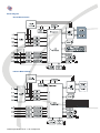
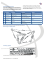
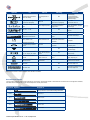
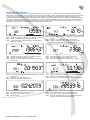
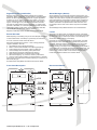
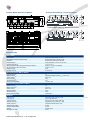
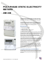
Poly-phase static electricity
meters
AM 350
The AM 350 series electricity meters are modern, electronic,
fully programmable devices, designed for application in AMM
systems for monitoring and control of electricity consumption.
The AM 350 electricity meter meets remote data transmission
requirements and enables readouts of various measurands.
The meter is MID certified as well as WELMEC 7.2 compliant
and has been designed to serve billing purposes.
Measuring System
The AM 350 series electricity meter:
●● Is a poly-phase static device;
●● Has one- to four-tariffs;
●● Measures active energy in class A or class B;
●● Complies with EN 50470-1 and 50470-3;
●● Is designed for direct connection.
At the heart of the measuring part is the MSP430 microprocessor that executes
all major calculations and operations. It converts analog signals from current
and voltage sensors to digital, calculates electric and other measurands,
evaluates tariff inputs, communicates via optical interface locally and generates
IR and S0 impulses. It displays predetermined measurand values and
logs them to memory. Via the communication module, the microprocessor
communicates with the head-end collection software, data concentrator,
customer display and slave measuring devices.
A current measuring transformer ensures galvanic separation of current and
voltage circuits within electricity meter measuring range. The measuring system
enables measurement even if harmonic components are present in the circuit
measured (voltage or current). Negative impact of DC components is eliminated
in each measuring period. Measuring system calibration is performed by
programme routines. The measuring system includes no mechanically
adjustable components.
Communication with linked slave devices and head-end collection software
can be done via two exchangeable communication modules. The modules
are used to relay measurand data to the customer display and, if need be, to
capture data from up to 8 slave measuring devices (water meters, gas meter,
calorimeter,..) and for communication with the master communication node –
the data concentrator, or directly with the head-end collection software. The
modules includes a back-up battery also.
Current Measurement Range - Direct Measurement
The AM 350 series electricity meters measure from start-up current up to Imax
with ample reserve, while complying with the DC components and harmonic
components standards. In the > 100 A range, the electricity meter will measure
with required accuracy provided the DC components of the current do not
exceed 80 A.
Technical specification No: A - 7 • 28 • 03, April 2011
Block Diagram
Direct Measurement
Indirect Measurement
Technical specification No: A - 7 • 28 • 03, April 2011
Displaying Measurand Values
The meter display can show a wide array of measurand values in
various modes. The modes can be normal, service and battery. The
battery mode becomes active during power outage, when the meter,
with a button being pushed, will display limited data only. A special
command will switch the meter over to service mode. Except for the
No. Mode Name
preceding situations, the meter is in normal mode. In each of the
modes said, measurand data to be shown and display sequence
can be preset both for automatic rotation and for manual control via
push buttons. Pressing of appropriate push button scrolls measurand
values up and down on the display.
Mode Entry
Mode Exit
Remark
Display is not back lit
Standard customer mode of display, billing
data available
M0
None
During power outage
Press push button to enter M5; Power
supply enters M2
M1
Standard Manual
As preset, if power supply is on or from M2
if push button is pressed
Timeout enters M2; Command enters M4;
Power outage enters M0
M2
Standard Self-rotation
As preset, if power supply is on or from M1
after timeout
Press push button to enter M1; Command
enters M4; Power outage enters M0
M3
Service Manual
As preset, if command is entered and push
button pressed
Timeout enters M4; Power outage enters
M0
M4
Service Self-rotation
As preset, if command is entered or from
M3 after timeout
Press push button to enter M3; Power
outage enters M0
M5
Battery
If push button is pressed during power
outage
Power supply enters M2; Timeout enters
M0 and turns display off; can be turned on
again after preset period
Remarks: Timeout refers to period when no push button is pressed. Display is back lit in M1 thru 4.
Status Diagram of Display Modes
LCD Display Symbols
The following table lists information presented by individual display segments when lit or not lit, flashing.
Technical specification No: A - 7 • 28 • 03, April 2011
Service technician information, data for
analyses
Power saving mode, limited data displayed
only
Symbol
T1 a T4
Lit
Not Lit
Flashing
Remark
- P Active Supply
+P Active Consumption
+Q Reactive Consumption
- Q Reactive Supply
Prevailing energy flow direction
(active and reactive)
No consumption and no
supply
Battery replacement approaching
(10% thru 5% capacity left)
Battery OK
Battery to be replaced at once
(less than 5% capacity left)
Battery status:
100% thru less than 5 %
Present phase voltage, correct
order
Phase voltage not present
Incorrect phase voltage order
or at least one phase is in
supply mode
Phase voltage presence and
correct order indication; indication
of power supply
N/A
kWh, VA, h, V, A, W, …
N/A
Unit symbols for OBIS code
displayed
Active tariff
N/A
Indication of currently active tariff
Approximate consumption See
description of bar chart below
Consumption over 90% of
Pmax
Approximate active output
Active, Limitation is On
Inactive, Limitation is Off
Limiter tripped the
disconnector, push button to
reconnect
Limiter – limits current and / or
consumption
Disconnected permanently,
no reconnection if push button
pressed
Connected
Disconnected, push button to
reconnect
Disconnector of circuits powered
by electricity meter
N/A
Universal sign - Description on
label under display
N/A
Status of relay switch-over
contacts of relay
Relays switched on, A2 + A3
(R1), B2 + B3 (R2) are coupled
Relays switched off,A2 +
A1 (R1), B2 + B1 (R2) are
coupled
Nonstandard event - alarm
occurred
No Nonstandard event
-allarm occurred, all
Warning – Nonstandard eventalarm
Non-standard event - alarm
magnet, tampering, etc.
Logged on, communication done
within timeout limit
Logged off, timeout tripped
communication
Error during communication
Meter link to head-end collection
software / data concentrator
Code Value
N/A
OBIS code, height 5 mm
Measurand Value
N/A
Measurand Value displayed as per
OBIS code, height 9 mm
Remark: N/A stands for Not Applicable under standard conditions
Bar Chart Description
The bar chart is used for approximate indication of consumption. Appoximate values of individual bars in barchart can be configured. Therefore,
the table sets an example only. Power values depend on actual power factor.
Segment Symbol
1
Output 1F
Start-up current 0.01 A, the meter is starting measurement
1 and 2
75W cca 0,1A
1 to 3
300W cca 0,4A
1 to 4
750W cca 1A
1 to 5
3 kW cca 4,3A
1 to 6
15kW cca 22A
Technical specification No: A - 7 • 28 • 03, April 2011
Display Indication Examples
The LCD displays measured values, unit of the measured quantity (e.g. kWh, kW, V, A, h and others). Lower 7-segments on the left indicate
OBIS codes, higher 7-segments on the right indicate the actual value of the register; the bar chart indicates the orientation size of the consumed
or supplied active output. In case of power supply, the bar chart is flashing. The battery symbol indicates the voltage status of the back-up
battery. The battery symbol is lit if the time of replacement of the battery is coming near and is flashing if it is necessary to exchange the battery.
The battery is located in the communication module and it can be replaced without intervention into the measuring parts of the electricity meter.
Other signs are used for displaying the auxiliary (explanatory) data, e.g. actual tariff, status of relay, disconnecting switch, limiter,… Specific
application of the symbols ▼ is on the description of the label of the electricity meter.
Line 1 Indication of consumption +P; Phases L1, L2 a L3 present; Tariff T1 active
Line 2 Register 1.8.2 value (consumption in tariff T2) 1358.4 kWh
Line 3 Logged-on (connected to master node); Relay R1 on; Bar Chart shows
approximate consumption
Line 1 Indication of supply -P; Phases L1, L2 present (L3 = supply flasches); Tariff
T3 active
Line 2 Register 34.7 value (instantaneous output) -1.679 kW (supply)
Line 3 Logged-on (connected to master node); Alarm; Relays R1 and R2 on;
Limiter active; Bar Chart shows approximate supply = flashes
Line 1 Indication of consumption +P; Phases L1, L3 present; Tariff T2 active
Line 2 Register 22.8.0 value (consumption) 19864.3 kWh
Line 3 Logged-on (connected to master node); Limiter active; Bar Chart shows
start-up current
Line 1 No consumption; Phases L1, L2 a L3 present; Tariff T4 active
Line 2 register 32.7 value (instantaneous voltage) 236.8 V
Line 3 Disconnector tripped and ready for reconnection (sign is flashing)
Line 1 No consumption; Battery replacement approaching; Phases L1, L2 present;
Tariff T2 active
Line 2 Register 0.9.1 value (actual time) 20:19:33
Line 3 Relay R2 on; Disconnector tripped permanently
Line 1 Indication of consumption +P; Phases L1, L2 a L3 present; Tariff T3 active
Line 2 Register 31.7 value (instantaneous current) 50.738 A
Line 3 Alarm; Relays R1 and R2 on; Bar Chart shows approximate consumption
Line 1 No consumption; No phases present; Tariff T1 active
Line 2 register 0.9.2 value (actual date) 10.4.2009
Line 3 Relays R1 and R2 on
Line 1 No consumption; Phases L1, L2 a L3 present; Tariff T4 active
Line 2 Register C.50 value (meter operation time) 28539 hours: 16 min
Line 3 Logged-on (connected to master node); Limiter tripped the disconnector
and both are ready for reconnection (both are flashing)
Technical specification No: A - 7 • 28 • 03, April 2011
Tariff
The AM350 series electricity meters can manage up to 4 tariffs.
Tariff switching is done either according to plan or directly. The plan
is set in a time switching table (switching function - scheduler). Direct
switching is executed via external tariff inputs or communicated - by
a command from the head-end collection software. Switching priority
is set in the meter configuration. Tariff currently active is indicated by
LCD symbols T1 thru T4 on the display.
Calibration LED
The meter is equipped with a testing (calibration) LED (usually red
or IR). Diode flashing frequency is directly proportional to energy
consumed. The diode constant is configurable during production. As
a standard, the constant is set to 10,000 imp / kWh and is marked on
the meter label.
Impulse Output S0
The impulse output S0 is connected to meter auxiliary terminals Nos.
20 and 21. Its output is connected with an open collector. Therefore,
external supply voltage needs to be connected, refer to Terminal
Board Wiring. Impulse output frequency is directly proportional to
energy consumed. The constant is configurable during production. As
a standard, the constant is set to 100 imp / kWh and the impulse width
to 40 ms. These data are marked on the customer label.
Optical Output
The optical interface complies with IEC 62056 mode C, and enables
direct local meter readout. Readout is done via the optical head
placed on the proper spot of the meter (right of the display above the
push buttons). The optical head electrical input / output is connected
to the RS 232 or USB ports of the PC or mobile equipment (PDA).
The meter can be configured via this interface based on preset access
levels.
Communication speed can be configured. Initial speed as a rule is
set to 300 Bd in line with revelant standard. After communication is
established, communication speed can be increased up to 9600 Bd
(depending on optical head used).
Two modes are available for readout – service and standard, same
applies for display. A special command is used to switch the meter
over to service mode. In other cases and after a power outage,
the meter is set to standard mode. In both modes, it is possible to
configure data to be read out, with respect to format and sequence.
Push Buttons
Both push buttons (top and bottom) are used for manual scrolling of
displayed data. A longer pressing of both push buttons at the same
time reverses meter disconnector position, thereby connecting or
disconnecting all circuits powered by the meter. A push button can
be accessed by opening the (sealable) meter communication module
cover. This push button is used for service purposes.
Optional Communication Modules
The meter has a slot for the installation of up to two communication
modules. The function of the modules is to manage communication
in the AMM system, relay data from/to the meter, communicate with
the customer display CID, slave measuring devices (water meters,
gas meter, calorimeter, etc.) and to communicate with the headend collection software. In addition, the module includes a back-up
battery to operate the meter during a power outage. The battery, after
the communication module and module covers have been opened,
can be easily replaced without intruding into the meter measuring
compartment.
The module communicates via GSM/GPRS, PLC, Ethernet, RS 485,
MBus and RF (Coronis 868 MHz) interfaces. The communication
modules include LED diodes, indicating module status. The modules
for the AM 350 meters have a designation xxM 350, e.g.: BTM 350,
Technical specification No: A - 7 • 28 • 03, April 2011
PLM 350, GSM 350, RSM 350 etc. For more information on modules,
refer to Technical Specifications of individual modules.
Logging-on to the Head-end Collection Software
When hooked to mains, the meter, if equipped with a communication
module, will by itself relay a log-on message to the head-end
collection software. If the head-end collection software confirms
message receipt, the meter is logged-on. If not, after some time,
the meter repeats its log-on message. The communication module
indicates communication status. Log-on status is shown on the
display. After a successful log-on, the meter can execute commands
received from the head-end collection software and relay data
required.
Customer Display Connection
An intelligent remote display (labelled CID) is used for communicating
with the meter and for showing data on a customer preset place.
CID and meter communication is either RF or PLC. The CID can be
powered either by battery or from accumulators that can be recharged
by an adapter hooked to mains. The CID can show all slave meters
(water meters, gas meter, calorimeter, etc.) profiles and much more
information.
The head-end collection software communicates with the user
by sending text messages to the user´s CID, whereby the user is
informed e.g. about credit status as well as other organizational and
operational issues (planned outages, notices, warnings, etc.).
Meter Registers
A complete register list depends on the meter FW. Key are energy
registers, divided up into energy flow, phases, tariffs, and sum
registers. Available are TOU (time of use) registers and maxima
registers, Pmax or Imax. Other auxiliary registers show instantaneous
effective values of voltage, current, active power and power factor.
The meter also includes special registers for slave meters linked with
it (water meters, gas meter, calorimeter, etc.).
Meter Registers setup details are listed in the Customer Sheet.
Real Time Clock (RTC) with Back-Up
The meter firmware is equipped with RTC with date. The RTC can be
adjusted via the optical interface locally or remotely via communication
module. A battery with a long service life backs up the RTC during
power outages. The battery is mounted in the communication module
and can be replaced without intruding into the meter measuring
compartment. Battery status is shown on the display. RTC accuracy
is according to EN 62054-21 and back-up time (battery capacity and
service-life) is at least 15 years. Other meter functionalities making
use of the RTC: Scheduler, Events Recorder, Registers History and
Profiles, etc.
Switching Function (Scheduler)
The RTC is used by the calendar (Scheduler) to manage switching of
up to 4 tariffs. These tariffs can operate up to two auxiliary relays that
govern other appliances (water heater, direct heating panels,…). This
functionality can replace an existing RCR system. Tariff and auxiliary
relay switching can, but need not, depend on each other. Relay status
is shown on the display. Number of logs in Scheduler is limited by
meter memory (preset to 255 lines).
Scheduler setup details are listed in the Customer Sheet.
Registers History
The scheduler is also used for logging register values at a preset time.
For example, logged can be energy registers at the end of the billing
period (e.g. last day of month at 23:59:59). Used memory size limits
number of logs (as a rule set to 15 monthly values).
Registers History setup details are listed in the Customer Sheet.
Registers Profile (Load Profile)
Alarm Messages (Alarms)
Based on meter RTC, up to 8 different registers can be logged
periodically. Meter configuration includes selection of these registers.
Number of values logged is configurable also. A typical application
is setting of a 15 min. profile of active energy register 1.8.0. Used
memory size limits number of logs (as a rule set to 1000 records ≈
approx. 3 months @ 15 min). Via some communication modules,
the meter can gather data from slave equipment, e.g. water meters,
gas meter, calorimeter, etc. From data gathered, the meter can build
consumption profiles of said meters. These profiles, like other data,
can be relayed to the head-end collection software.
Alarm messages can be optionally assigned to preset events. The
meter always logs alarms and relays them to the head-end collection
software. As a rule, alarms comprise meter tampering (opening of
meter /terminal block/ communication module covers). A meter that
relayed an alarm seeks confirmation from the head-end collection
software, otherwise it will repeat that alarm after some time. This
functionality turns the meter into an active component of the AMM
system.
Registers Profile setup details are listed in the Customer Sheet.
Limiter
Events Recorder
The limiter is an electronically controlled disconnector. If the limiter
disconnects the equipment (for any reason), reconnection is possible
by meter push buttons, external push button or remote display. The
disconnector status is shown on the display.
Meter tampering or exceeding of any limit is time stamped and logged
to an Events Recorder. Time stamp is governed by the meter RTC.
As a rule, customers monitor events as follows:
Strong DC magnetic field occurrence – when a strong permanent
magnet is attached / removed;
●● Terminal Block Cover opening (tampering);
●● Meter / Communication Module Cover Opening (tampering);
●● Power Outages and Drops below / above a preset limit;
●● Current average value monitoring, within preset limits;
●● Tariff switching (except for scheduler driven activity);
●● Relay switching (except for scheduler driven activity);
●● Disconnector tripping – by customer, Limiter or push buttons;
●● Current / Power maxima resetting via optical interface or remotely
Used memory size limits Events Recorder capacity (as a rule set to 10
last events per type).
Alarm Messages setup details are listed in the Customer Sheet.
The limiter can operate in two modes. In the first mode, it monitors
that the phase current limit value over a defined time period is not
exceeded. Should this happen, the limiter disconnects the circuits
powered by the meter. In the second mode, it monitors floating
average of energy consumption over a defined time period (similar to
¼ hour maximum). If exceeded, disconnection takes place again. The
limiter can have up to 2x8 preset limit values (8x current, 8x power).
However, only one limit of each can be active at one point in time.
Limiter setup details are listed in the Customer Sheet.
Events Recorder setup details are listed in the Customer Sheet.
Front Panel Description
Technical specification No: A - 7 • 28 • 03, April 2011
Dimensional Sketch
Terminal Board Dimensional Sketch
Terminal Board Wiring – Direct Connection
Terminal Board Wiring– Indirect Connection
Technical Data
Basic Data
Accuracy Class
Electricity Meter Constant (testing LED output)
Connection
Nominal Voltage UN
Operation Voltage Range
Actual Consumption of Each Voltage Circuit (module not inserted)
Actual Consumption of Each Current Circuit
Nominal Frequency
Operation Frequency
class A or B as per EN 50470-1, 50470-3
programmable, usually 10 000 imp. / 1 kWh
direct four-wire or indirect (via transformer)
As per pre-requisite 3 x 100 V to 3 x 230 / 400 V
0.75 UN to 1.15 UN
maximum 1.5 W, max. 5 VA capacitive
maximum 0.01 VA
50 Hz
45 Hz to 55 Hz
Direct Electricity Meter AM350
Reference Current IREF
Maximum Current IMAX
Start-Up Current IST
Minimum Current IMIN
Transitional Current ITR
Maximum Measuring Range
5A
configurable in integer multiples of IREF: 40 A thru 100 A
below 15 mA
0.25 A
0.5 A
15 mA thru 125 A
Indirect Electricity Meter AM350
Reference Current IREF
Maximum Current IMAX
Start-Up Current IST
Minimum Current IMIN
Transitional Current ITR
Maximum Measuring Range
5A
6 A or 10 A
below 15 mA
0.05 A
0.25 A
5 mA thru 10 A
Outputs
Testing IR Output
Pulse Output S0
●●Output Connection
●●Number of Impulses
●●Width of Impulses
●●Nominal Supply Voltage
●●Maximum Supply Voltage
●●Current
Wiring Maximum Length
Technical specification No: A - 7 • 28 • 03, April 2011
configurable, usually 10 000 imp. /1 kWh
class A as per EN 62053-31
direct, two-wire, open collector output type
configurable 0.15 thru 10 000 imp. / 1 kWh
configurable, standard setting to 40 ms
24 V DC
30 V DC
5 thru 15 mA DC
1000 m
Output Relay Parameters
Number of Output Relays
Switching Capability of 1 Output Relay, Permanent
Maximum Sum of Currents of 2 Output Relays
Output Relays Electrical Service Life (with maximum load)
Output Relays Mechanical Service Life
2
IC 8 A permanently, cos φ = 1
total 16 A, cos φ = 1
minimum 2 x 10⁵ cycles ON/OFF
minimum 1 x 10⁶ cycles ON/OFF
Disconnector Parameters
Maximum Tripping Current
Disconnector Electrical Service Life (with maximum load)
Disconnector Mechanical Service Life
IC 100 A permanently, cos φ = 1
minimum 5 x 10³ cycles ON/OFF
minimum 1 x 10⁶ cycles ON/OFF
Real Time Function
Accuracy
Back-Up Time
Battery Type
as per EN 62054-21
minimum 15 years
Li-SOCl2
Battery Capacity
minimum 1200 mAh
Battery Nominal Voltage
3.6 V
Impact of Surroundings
Temperature Range
●●Operation
●●Extended Operation
●●Storage
●●Extended Storage
Ingress Protection
-25°C thru + 55°C
-40°C thru + 70°C
-35°C thru + 65°C
-40°C thru + 70°C
IP 51 as per EN 60529
Resistance to Voltage Impulses
Impulse Voltage
Impulse Shape
6 kV
1.2 μs / 50 μs
Resistance to Permanent Overvoltage
Voltage Between Phase and Neutral Wire
up to 450 V
Electromagnetic Compatibility
Electrostatic Discharges
Test Voltage
Number of Discharges
High-Frequency Electromagnetic Field
●●Difficulty Level 3, Vertical and Horizontal Polarization
●●Frequency Zone
●●Electric Field Intensity
Fast Transient Phenomena (Impulse Groups)
●●Impulse Groups Time
●●Impulse Groups Period
●●Test Time
●●Test Voltage
Radio Interference Suppression
●●Peak Course of Interference Voltage within Band
●●Peak Course of Electromagnetic Field Intensity within Band
Resistance to Interference Propagating Along Wiring as per EN 61000-4-6
as per EN 61000-4-2
8 kV
10
as per EN 61000-4-3
80 MHz thru 2 GHz
30 V/m
as per EN 61000-4-4
15 ms
300 ms
60 s
4 kV
as per EN 55022
0.15 ÷ 30 MHz
30 ÷ 2000 MHz
0.15 ÷ 80 MHz
Weight and Dimensions
Weight – Module Not Inserted
Width
Height
Depth
Installation as per Dimensional Sketch (width x height)
●●Case Dimensions
●●Operating Position
about 2.7 kg
170 mm
280 mm
99 mm
150 mm x 230 mm
as per DIN 43857
vertical
Connection of Current and Neutral Wires
Terminals Diameter
Wire Cross-Section Maximum
Wire Cross-Section Minimum
Connecting Screws
Head Shape and Diameter
●●Cross Groove
Technical specification No: A - 7 • 28 • 03, April 2011
7.2 mm
35 mm2
4 mm2
M6 x 12 mm
CH (cylindrical head) / 6.5 mm
SL-PZ (Combination Slot – Pozidrive, size 2 as per ISO 4757)
●●Strength Class
Torque
5.8
5.6 (M6) Nm
Connection of Auxiliary Wires
Terminals Diameter
Wire Cross-Section Maximum
Wire Cross-Section Minimum
Connecting Screws
●●Head Shape and Diameter
●●Groove
●●Strength Class
●●Torque
3.2 mm
6 mm²
0.75 mm2
M3 x 6 mm
PN (half-round head) / 5.3 mm
SL-PZ (Combination Slot – Pozidrive), size 1 as per ISO 4757
5.8
0.7 Nm
Non-specified parameters as per EN 62052-11, EN 62053-21 and MID Directive (EN 50 470-1, EN 50 470-3)
Meter Design
Installation Execution
The AM 350 electricity meter, stemming from a design traditionally
proven, is designed so as to withstand demanding operation
conditions, enable simple handling and deliver increased protection
from unauthorized consumptions. The design solution offers a simple
installation. The installation is done using three screws to an A-Base.
The vertex can be adjusted by sliding the hook to achieve two
dimensions - 210 mm and 230 mm (DIN 43857). The set of sealing
positions safeguards various concealed parts of the meter from
unauthorized entry. The meter case and terminal block dimensions
comply with DIN 43857. The meter cover enables stacking of the
meters during storage.
Prior to and during installation, the following shall be observed / used:
The vertically asymmetrical meter display is located in the meter
upper half. The meter can be equipped with up to two exchangeable
communication modules. The modules can be exchanged without
intruding into the meter compartments. The modules are mechanically
and galvanically (except for mains power supply) separated from
the meter electronics. Modules are described in detail in individual
Technical Specifications.
Meter with correct designation, correctly filled-in label, prescribed
seals;
●● M
eter Wiring Diagram;
●● Prescribed connecting material for meter connection (screws, ...);
●● Seals and sealing pliers for sealing of cover plates and terminal
cover;
●● Prescribed, undamaged tools;
●● Measuring device or indicator with buzzer.
●● Wires Connection
●● Supply wires to be checked to be voltage free;
●● Supply wires to be deinsulated in sufficient length;
Wires to be inserted in corresponding terminals of terminal block,
terminal board screws to be tightened with torque of 3 to 5 Nm.
If wires cross-section is small, it is necessary to pay attention to their
correct location in the terminal block. The correct location of the wire
is inside the terminal block groove. Usage of a measuring device is
recommended for verification of correct wire attachment.
Installation
Installation Inspection
Installation is done using three screws to an A-Base.
To be checked after installation:
The set of sealing positions safegueards various parts of the meter
from unauthorized entry.
●● M
eter identification number to match meter prescribed location;
●● Connection of bridge between voltage and current terminals (1 and
2) in the terminal block upper part;
●● Perfect tightening of terminal block screws;
●● Correct connection order of input and output wires;
●● Proper connection of neutral wire – incorrect connection can result
in meter breakdown;
●● Meter functions – applicable LEDs are to be lit and correct signs
displayed on display (no error messages present);
●● Correct tariff switching and identification.
Installation inspection completed successfully, the terminal cover is to
be installed and sealed.
Installation Authorization
To install the meter, the following pre-requisites shall be observed:
●● Installation may only be done by knowledgeable persons or persons
with higher qualification that were adequately trained;
Installation may be done only on surfaces for such purpose prepared
and modified. This is to be checked prior to installation start;
●● Installation may be done in line with wiring conditions of the user.
Screws Tightening Torque
Screws Tightening Torque
M6 x 12
3 thru 5.6 Nm
4 mm2 wire minimum cross-section
Other connecting terminals
M3 x 6
0.7 Nm
1.5 mm2 wire minimum cross-section
Sealing screws of covers
M4
0.5 Nm
3 mm seal hole diameter
Technical specification No: A - 7 • 28 • 03, April 2011
Troubleshooting
Display did not light up
♦♦ No voltage in supply wires
♦♦ Bridge between terminals 1 and 2 disconnected
♦♦ Meter designed for different voltage
Symbol E flashes and voltage value 310 V displayed
♦♦ Overvoltage occurred, e.g. 280 V or higher measured against N
L1, L2, L3 symbols flash alternatively
♦♦ Incorrect order of phases (switch leads of any two phases)
Bar chart flashes
♦♦ Incorrect connection – reversed order of L and N
♦♦ Customer owned energy source (supply) at work
Meter not communicating with reading device (PDA, PC ...)
♦♦
♦♦
♦♦
♦♦
♦♦
Optical head not connected to PC, PDA, …
Incorrectly set up serial port on PC, PDA, …
Incorrectly set up start-up speed
Incorrectly selected meter address
PC, PDA SW does not support meter
Meter not communicating with head-end collection software
♦♦
♦♦
♦♦
♦♦
♦♦
Communication module not connected
Communication cable not connected
Poor communication signal
Meter unknown to head-end collection software
Meter with incorrect (or missing) AMM address
Type designation
AM 350. # . # # - # # . # # - # # . #
Direct Connection
D
Indirect Connection
I
With No Disconnector
0
With Disconnector, Maximum Current of Disconnector = Imax of Meter
1
#
#
Communication Module Type
●●
Internal Communication Module
I
●●
Exchangeable Communication Module
E
●●
Several Exchangeable Communication Modules
B
●●
Internal Exchangeable Module
C
●●
With no Communication Module
N
FW Version
HW Modification
Internal Module Type
00-99
00-99
M0-M9
With No External Tariff Control
0
Internal Coupling of Tariffs to L
1
Internal Coupling of Tariffs to Terminal 15
4
Internal Coupling of Tariffs to N
5
With No External Tariff Switching
X
Tariff Switching – Czech Logic
C
Tariff Switching – European Logic
E
Tariff Switching – Customer Logic
Z
One-Tariff
1
Two-Tariff
2
Three-Tariff
3
Four-Tariff
4
One-Tariff with No S0
5
Two-Tariff with No S0
6
Three-Tariff with No S0
7
Four-Tariff with No S0
8
Technical specification No: A - 7 • 28 • 03, April 2011
Maintenance Requirements
Care and Maintenance
The meter is a maintenance-free device with prescribed minimum service life of 15
years.
The manufacturer discourages from using organic solvents, aggressive chemicals
and abrasive cleaning preparations for optional cleaning of external surfaces from
dust and other impurities. Prescribed storage temperatures are to be observed;
failure to comply with these can shorten electronic parts service life. The meter is
to be protected from humidity and moisture. Precipitations, humidity and liquids
contain minerals, which cause corrosion of electrical circuits. If the meter becomes
wet, it should neither be placed on nor dried by placing on or in a heat source (e.g.
microwave, stove or heating bodies). The meter can overheat and some of its
parts explode. The meter is not to be exposed to excessive heat; this can lead to
covers deformation. The meter is not to be stored in cold premises. Humidity could
condensate in the meter, (especially if warming up to nominal operation temperature
follows), and damage meter electronic parts or have adverse effect on the meter
insulation properties.
Switching to Service Mode (Commands Description)
PC → ELM / ? Address of location! CR LF
PC ← ELM / ZPA4AM350.v70_004CR LF
PC → ELM ACK 0 Z 1CR LF
PC ← ELM SOH P 0 STX (Data) ETX BCC
PC → ELM SOH P 1 STX (Password) ETX BCC
PC ← ELM ACK
PC → ELM SOH E2 STX 0101() ETX BCC
PC ← ELM ACK
PC → ELM SOH B 0 ETX BCC
PC ← ELM ACK
This command switches the meter over to the service mode, in which
the meter verification period can be shortened. In this mode, the meter
displays energy values with four integer digits before and up to four
digits after the decimal point. Via the IR optical head designed as per
EN 62056-21, the verification station sends this command to individual
meters. This mode ends automatically after the meter is disconnected
from the mains.
Service
ZPA Smart Energy a.s trademark SMART ENERGY
Komenského 821
Tel.: +420 499 907 111
541 01 TRUTNOV
Fax: +420 499 907 497
Czech Republic
E-mail: [email protected]
http:// www.zpa.cz
300 Bd
Z Bd
Meter Transport
The meter shall be packed for transport either in the original package, in which it was delivered by the manufacturer, or in such a package that
can cause no damage resulting from handling or transport.
Packaging Materials and Defunct Device Disposal
The devices at the end of their service life are to be handed over to specialized organizations, engaged in separation of used materials or their
recycling. Unused devices are to be disposed of ecologically, in compliance with the Waste Act.
Device. Contains no radioactive, carcinogenic or other material harming human health or environment. All plastic material used is recyclable.
Packing Materials. Packing boxes are recyclable. Hand used boxes over to organizations as a source of secondary raw material or energy.
Manufacturer‘s Warning
The device is capable of safe operation. The manufacturer issued a Declaration of Conformity as per Sect. 13 of the Act 22/97 Coll.
However, despite the said above, the manufacturer warns of the risk of possible danger resulting from incorrect device handling or application
as follows:
●● Installation and maintenance needs to be performed by a knowledgeable person with corresponding electrotechnical qualification, that will
inform the operator on conditions of safe operation;
●● The device may not be used for purposes other than those it was manufactured for;
●● The device may not be wilfully modified contrary to its type design;
●● The device may not be operated with different voltage, current and frequency than those it was produced for or professionally modified for;
●● The device shall be located and secured so as to complicate or disable handling by persons with no electrotechnical qualification, especially
children;
●● Before every putting into operation, e.g. after repair, maintenance, etc., Ingress Protection is to be fully restored, all safety measures taken and
revision done by an engineering inspector;
●● During operation, premises where the device is installed have to be free of danger of fire or explosion in case of occurrence of gases, vapours
of inflammable liquids and occurrence of inflammable dust;
●● The device may be handled by a knowledgeable person only, handling performed without voltage with the exception of measurement by
measuring device with insulated tips;
●● The device may not be operated under conditions or in an environment not ensuring safe operation (e.g. location on inflammable base, cover
from inflammable material, insufficient protection from penetration of foreign elements or water or other liquids);
●● The device may not be operated with vibrations and oscillations exceeding those specified in the technical specification.
Should the user fail to respect any of the aforesaid warnings and should any defect occur as an incidental consequence of such a failure, the
manufacturer shall not be liable for the defect.
ZPA Smart Energy a.s., Komenského 821, 541 01 Trutnov, Česká republika
Tel.: +420 499 907 111, fax: +420 499 907 497
E-mail: [email protected], http.: //www.zpa.cz
Technical specification No: A - 7 • 28 • 03, April 2011