1
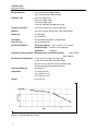
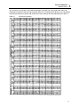
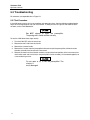
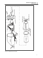
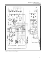
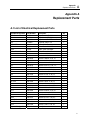
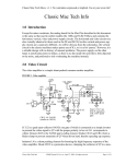
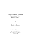
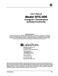
Victoreen 470A
Panoramic Survey Meter
Operators Manual
March 2005
Manual No. 470-166-1 Rev. 6
©2004, 2005 Fluke Corporation, All rights reserved. Printed in U.S.A.
All product names are trademarks of their respective companies
Fluke Biomedical
Radiation Management Services
6045 Cochran Road
Cleveland, Ohio 44139
440.498.2564
www.flukebiomedical.com/rms
Table of Contents
Section 1:
1.1
1.2
1.3
Introduction................................................................................................ 1-1
Product Description ..................................................................................... 1-1
Specifications............................................................................................... 1-1
Procedures, Warnings, and Cautions .......................................................... 1-3
Section 2:
2.1
2.2
2.3
2.4
2.5
Installation.................................................................................................. 2-1
Unpacking.................................................................................................... 2-1
Power Requirements ................................................................................... 2-1
Precautions.................................................................................................. 2-2
Routine Cleaning ......................................................................................... 2-2
Storage ........................................................................................................ 2-3
Section 3:
3.1
3.2
3.2.1
3.2.2
3.2.3
3.2.4
3.2.5
3.3
3.4
Operation.................................................................................................... 3-1
Function ....................................................................................................... 3-1
Controls ....................................................................................................... 3-1
Range Switch ......................................................................................... 3-1
Function Switch ...................................................................................... 3-1
Zero Set.................................................................................................. 3-1
Zero Adjust ............................................................................................. 3-1
Calibration Potentiometer and 22 ½ V Battery Switch ............................ 3-1
Operating Procedure (Turn-On Sequence).................................................. 3-2
Operational Tests ........................................................................................ 3-2
Section 4:
4.1
Theory of Operation................................................................................... 4-1
General Theory............................................................................................ 4-1
Section 5:
5.1
5.1.1
5.1.2
5.1.3
5.1.4
5.1.5
5.2
5.2.1
Adjustment and Maintenance ................................................................... 5-1
Calibration.................................................................................................... 5-1
Energy Dependence............................................................................... 5-1
Temperature and Pressure..................................................................... 5-1
Angular Dependence.............................................................................. 5-1
Source Distance ..................................................................................... 5-1
Calibration Procedure............................................................................. 5-1
Troubleshooting ........................................................................................... 5-2
Test Procedure ....................................................................................... 5-2
Appendix A: Replacement Parts ....................................................................................A-1
A.1
List of Electrical Replacement Parts ............................................................ A-1
i
(Blank Page)
Introduction
Production Description
1
Section 1
Introduction
1.1 Product Description
The 470A is unparalleled in health physics surveys instrumentation. The latest solid-state IC technology
has been utilized to miniaturize circuitry, reduce weight and increase reliability. Accuracy and
convenience have also been carefully considered to assure the best possible indication of true radiation
exposure. An extremely rugged high impact molded plastic case provides easy decontamination.
The 470A is ideal in numerous applications including:
•
Background studies
•
General health physics surveys
•
Radiochemical lab checks
•
Surveying nuclear power plants
•
Monitoring x-ray and radiotherapy facilities
•
Fuel processing plants
•
Research labs
•
Certain NDT applications
1.2 Specifications
Range
Rate: 0-3, 10, 30, 100, 300, 1000 mR/h and R/h
Integrate: 0-3, 10, 30, 100, 300, 1000 mR
Radiation Detected
Alpha, beta, gamma and x-ray
Detector
Unsealed air ionization chamber
Material
Expanded polystyrene/275 cc vol
Wall Thickness
17 mg/cm2
Cycolac Equilibrium Sleeve/Cap
500 mg/cm2 thick
Readout Meter
3.125 in (7.9 cm) scale, taut band movement
Controls
External: Function Switch (R/h, mR/h, mR integrate)
Range Switch (Off, Battery Check, 1000, 300, 100, 30, 10, 3)
Zero Set
Zero Adjust
Internal: Calibration Adjustment
High Voltage Check Switch
Coarse Zero Adjust Potentiometer
1-1
Victoreen 470A
Operators Manual
Energy Response
±15% from 8.0 keV to 300 keV-bare
±10% from 40 keV to 2 MeV-Covered
Response Time
8 sec on 3 mR/h range
3 sec on 10 mR/h range
2 sec on 30 mR/h range
1.5 sec on 100 mR/h and 300 mR/h range
Switching Transients
Less than 8 seconds on Function & Set Zero
Batteries
Two 1.5 V “D” cells and four 22.5 V No. 505 Eveready
Battery Life
“D” cells 150 hr
22.5 V shelf life
Zero Adjust
Can be properly adjusted in a radiation field
Warm-up Time
Less than one minute
Environmental Effects
Temperature Range: -20° to +120°F (-29° to +49°C)
Humidity Range:
0 to 95%, non-condensing
Geotropism:
negligible
Response to Other Radiation Minimum energy to penetrate chamber:
Alpha: 8 MeV
Beta: 120 KeV
Zero Drift with Temperature
6% per 10°C on 3 mR/h and 3 R/h range
2% per 10°C on 10 mR/h and 10 R/h range
0.6% per 10°C on 30 mR/h range and 30 R/h range
Can be completely eliminated by rezeroing
Collection Efficiency
See Figure 1-1
Dimensions
11 in long (27.9 cm)
4 ¾ in wide (12.1 cm)
9 ½ in high (24.1 cm)
Weight
Less than 4 lb
Figure 1-1. Collection Efficiency Graph
1-2
Introduction
Procedures, Warnings, and Cautions
1
1.3 Procedures, Warnings, and Cautions
The equipment described in this manual is intended to be used for the detection and measurement of
ionizing radiation. It should be used only by persons who have been trained in the proper interpretation of
its readings and the appropriate safety procedures to be followed in the presence of radiation.
Although the equipment described in this manual is designed and manufactured in compliance with all
applicable safety standards, certain hazards are inherent in the use of electronic and radiometric
equipment.
WARNINGS and CAUTIONS are presented throughout this document to alert the user to potentially
hazardous situations. A WARNING is a precautionary message preceding an operation that has the
potential to cause personal injury or death. A CAUTION is a precautionary message preceding an
operation that has the potential to cause permanent damage to the equipment and/or loss of data.
Failure to comply with WARNINGS and CAUTIONS is at the user’s own risk and is sufficient cause to
terminate the warranty agreement between Fluke Biomedical, Radiation Management Services and the
customer.
Adequate warnings are included in this manual and on the product itself to cover hazards that may be
encountered in normal use and servicing of this equipment. No other procedures are warranted by Fluke
Biomedical. It shall be the owner’s or user’s responsibility to see to it that the procedures described here
are meticulously followed, and especially that WARNINGS and CAUTIONS are heeded. Failure on the
part of the owner or user in any way to follow the prescribed procedures shall absolve Fluke Biomedical
and its agents from any resulting liability.
Indicated battery and other operational tests must be performed prior to each use to assure that the
instrument is functioning properly. If applicable, failure to conduct periodic performance tests in
accordance with ANSI N323-1978, paragraphs 4.6 and 5.4, and to keep records thereof in accordance
with paragraph 4.5 of the same standard, could result in erroneous readings of potential danger. ANSI
N323-1978 becomes, by this reference, a part of this operating procedure.
1-3
Victoreen 470A
Operators Manual
(Blank page)
Installation
Unpacking
2
Section 2
Installation
2.1 Unpacking
When unpacking the 470A, check for any in-shipment damage.
2.2 Power Requirements
Two 1 ½ volt and four 22 ½ volt batteries are supplied with each instrument. Before installing the
batteries be sure the Range Switch is in the OFF position. The “D” cells are installed in the handle by
removing the two side retaining screws that permit removal of the cap. The batteries are inserted and the
cap rep placed. Be sure to observe battery polarity. When replacing the cap be sure the contact spring is
properly oriented. See Figure 2-2.
To install the 22 ½ volt batteries, remove the five screws that hold the front of the instrument to the body
and pull the front forward. The battery holder is mounted to the front instrument assembly. Install the 22
½ volt batteries observing the proper polarity. (When mounting the front assembly to the body, dress the
interconnecting cable in a manner that will not cause interference.) Replace the five mounting screws.
See Figure 2-2.
The 22 ½ volt batteries provide chamber collection voltage and do not experience significant current
drain. Battery life is equal to shelf life that should be in excess of one year.
The BATT position on the Range Switch will check the condition of the D cells only, which must read in
the green area of the meter. Since the 22 ½ volt batteries will last for shelf life, they require only
infrequent checking. Checking may be accomplished by snapping out the logo plate located below the
meter and actuating a microswitch located on the left hand side of the opening. When the switch is
actuated, the meter will read about 95% of full scale. Note the reading for future reference to establish
battery condition. The batteries should be replaced when they have dropped about 5% below their initial
reading. This check must be performed with the Range Switch in the OFF position. See Figure 2-1.
The purpose of the collecting voltage is to supply the electrostatic field that sweeps the ions created in the
chamber to the walls and center electrode, where they constitute the current which is measured by the
electronics. This should be accomplished with as little recombination of these ions as possible. The
voltage necessary for a certain ion collecting efficiency varies as the square root of the radiation intensity
for a particular chamber geometry. Thus, since the chamber is 90% saturated at 1000 R/h at 90 volts, it
requires only about 50 volts to produce 90% saturation at 300 RIb, full scale on the next range. Hence,
the instrument is still quite useful, especially on the mR/h range, even if the collecting voltage has
dropped to as much as half its original level. The reason for noting the reading of collecting voltage and
replacing these batteries if the reading drops by about 5% is that such a decrease is a reasonable
indication of the battery shelf life.
2-1
Victoreen 470A
Operators Manual
Figure 2-1. View of instrument with the logo plate removed. (Showing Battery Test Micro Switch, Control,
and Coarse Zero Potentiometer)
2.3 Precautions
If the ion chamber is broken or contaminated with radioactive material, the chamber must be replaced.
Contact Fluke Biomedical for servicing.
2.4 Routine Cleaning
CAUTION
Do not immerse the 470A Panoramic Survey Meter.
The unit is not waterproof. Liquid could damage
the circuits. The unit should be kept clean and free
from dirt and contamination. The unit may be
cleaned by wiping with a damp cloth using any
commercially available cleaning or decontaminating
agent.
2-2
Installation
Storage
2
2.5 Storage
In areas where the humidity is exceptionally high, Ion Chamber instruments may become saturated with
moisture causing them to fail. To avoid this occurrence, store instruments in a typical dry box with either
a 100-watt light bulb or renewable dessiccant packet. Smaller instruments can be stored in polyethylene
bags with dessiccant
packet.
Figure 2-2. Batteries, Cap, and Contact Spring Replacement
2-3
Victoreen 470A
Operators Manual
(Blank page)
Operation
Function
3
Section 3
Operation
3.1 Function
The 470A is an ionization chamber meter used to detect alpha, beta, gamma and x-ray radiation. It
measures total exposure rate from 3 mR/h full scale for gamma and x-ray energies from 8.0 keV to 2
MeV.
3.2 Controls
The 470A has four front panel controls. See the following sections for details.
3.2.1Range Switch
The Range Switch has eight positions. It can turn the instrument OFF, check the battery voltage, or set
the sensitivity at 1000, 300, 100, 30, 10 or 3.
3.2.2Function Switch
The Function Switch determines whether the 470A measures R/h, mR/h or integrates mR.
3.2.3Zero Set
The Zero Set button is actuated whenever the instrument must be zeroed or operated in the Integrate
Mode.
3.2.4Zero Adjust
Since the instrument is susceptible to zero drift after initial turn on or when subjected to environmental
extremes, zeroing is provided and may be accomplished in high radiation fields.
Depress the Zero Set button and adjust the Zero Adjust control on the instrument until the meter reads
zero. Release the Zero Set button and the instrument is ready for operation. The zeroing procedure
should be followed before performing integration.
3.2.5Calibration Potentiometer and 22 ½ V Battery Test Switch
A calibration adjusting potentiometer, a coarse zero potentiometer, and a collecting voltage battery test
switch are located under the logo plate directly under the meter, see Figure 2-1. This logo may be
snapped out for access to these controls. The calibration potentiometer is factory adjusted and should be
readjusted only with a calibrated radiation source.
In the event that the instrument cannot be zeroed with the external zero control as in Section 3.2.4,
readjustment of the coarse zero control may be necessary. This is done by setting the external zero
control to the middle of its range, turning the instrument to one of its operating ranges, depressing the
Zero Set button and adjusting the coarse zero potentiometer till the indicating meter reads zero. The
external zero control will then have ample range in each direction.
3-1
Victoreen 470A
Operators Manual
3.3 Operating Procedure (Turn-On Sequence)
Turn the Range Switch from OFF to BATT and make sure the meter is in the BATT. O.K. green region.
Then turn the Range Switch to 1000. Push the Zero Set button and adjust zero as described in the
previous paragraph. Turn the Function Switch to mR/h. As the ion chamber bias voltage rises to -90
volts, the instrument will read upscale. This lasts for less than one minute after the instrument is turned
on.
After one minute, turn the range Switch to 3 mR/h. The instrument should now read background
radiation. The 470A is now ready to make measurements.
After warm-up, the Mode and Range may be selected with the Function Switch.
3.4 Operational Tests
First the 470A must pass the turn-on procedure. Then place a small radiation source nearby so the 470A
reads about 1 mR/h. Turn the Range Switch to the 10 mR/h and to the 30 mR/h range, the meter reading
should decrease on each range change to always indicate about 1 mR/h. If the 470A fails the turn-on or
operational tests, turn to Section 5.2, Troubleshooting.
The Operational Check Source on the end cap of the chamber equilibrium sleeve can be used for the first
of these tests. The Check Source consists of less than 0.01 microcuries of depleted uranium, and will
produce a reading of between 0.6 and 1.5 mR/h when the source is placed on top of or in front of the bare
chamber.
3-2
Theory of Operation
General Theory
4
Section 4
Theory of Operation
4.1 General Theory
When the ion chamber is exposed to radiation the internal air volume becomes ionized. A dc potential
applied between the outer shell and center electrode separates the newly formed ion pairs before they
can recombine and collects them. The ions, upon reaching the electrodes, are restored to neutral gas
atoms through the process of taking on (or giving up) electrons. This causes a direct current flow in the
external circuit. The ion chamber can be considered a constant current generator whose output current is
directly proportional to the rate of internal air ionization or exposure rate. These currents are extremely
small however, and special electrometer circuitry is required to measure them.
An operational, current-amplifier configuration is employed in this instrument, see Figure 4-1. The large
amount of negative feedback causes the output voltage to be a function of input current and feedback
element value, rather than amplifier gain or other variables. A MOSFET electrometer is used for the
operational amplifier. The feedback element is either a high megohm resistor or a capacitor.
Precision film resistors, elected by the Range Switch, determine the amount of dc voltage gain, and
hence, the full scale sensitivity of the instrument. A variable resistor is employed to calibrate accurately
the meter deflection to a known exposure rate radiation field.
Figure 4-1. Operational Amplifier (current amplifier configuration)
4-1
Victoreen 470A
Operators Manual
Figure 4-2. Energy Response Correction Curve
4-2
Theory of Operation
General Theory
4
This instrument is calculated in International Roentgens corrected to 0° Centigrade when used at 22°
Centigrade and 760 mm mercury (Hg) barometric pressure. For temperatures other than 22° Centigrade
and pressures other than 760 mm Hg, multiply the scale reading by the factor obtained form Table 4-1.
Table 4-1.
Air Density Correction
4-3
Victoreen 470A
Operators Manual
Figure 4-3. Source Distance
4-4
Theory of Operation
General Theory
4
Figure 4-4. 470A Angular Dependence
4-5
Victoreen 470A
Operators Manual
(Blank page)
Adjustments and Maintenance
Calibration
5
Section 5
Adjustments and Maintenance
5.1 Calibration
The 470A is calibrated at the factory. When field recalibration is performed, four correction factors must
be remembered.
5.1.1Energy Dependence
Any ion chamber has a certain energy dependence. That is, holding the exposure rate constant, the
chamber responds differently to different energy photons. The 470A has been calibrated at an effective
energy of 662 keV from 137Cs. The response is fairly energy dependent in the low-energy region. For
accurate usage at middle and high energy regions, the Energy Response Correction Curve must be used,
see Figure 4-2.
5.1.2Temperature and Pressure
Air, at standard temperature and pressure, is the ionized medium in the exposure rate definition. The
density of the air determines directly the ionization rate with all other factors held constant. The density
is, in turn, a function of barometric pressure and Kelvin temperature. Since the ion chamber is not sealed,
a small correction must be made for temperatures and barometric pressures different from those during
calibration. 0 Standard temperature, 0°C, is rarely encountered in practice. The 470A is calibrated and
corrected to 220°C and 760 mmHg. For different temperatures and pressures, correction factors will be
found on the Air Density Correction Table 4-1.
5.1.3Angular Dependence
The shape, wall material, center electrode design, and Position of the ionization chamber of the 470A
results in an instrument response relatively independent of the direction of the incident radiation. Figure
4-4 gives the relative angular response of the 470A with the equilibrium cap on and off respectively, at 1.3
MeV (60Co), and 120 keV and 40 keV effective.
5.1.4Source Distance
If a point Source or a collimated beam is used, the 470A chamber must be far enough from the source so
the entire ion chamber is uniformly exposed. In practice this means any point source should be at least 1
meter from the ion chamber. The center of volume of the chamber is 5.7 cm from the end. See Figure 43.
5.1.5Calibration Procedure
1. Set the 470A to the 1 R/h range. Zero the 470A.
2. Pull out the logo plate and look down through the opening at the circuit board. The calibration
potentiometer, R7, is the lower one on the right side. See Figure 2-1.
3. Subject the ion chamber to a Low R field and adjust the pot for the correct reading. Use the
equilibrium cap if the effective energy of the source is over 100 keV. Be sure to correct for
temperature, pressure, and energy response.
5-1
Victoreen 470A
Operators Manual
5.2 Troubleshooting
For reference, see exploded view in Figure 5-1.
5.2.1Test Procedure
If the 470A does not pass its turn-on procedure and operational tests, then the following troubleshooting
steps will check the batteries and main circuit board. If these parts test all right, but the 470A still does
not work, contact Fluke Biomedical.
CAUTION
Do NOT attempt to repair the preamplifier.
Tampering with it could void the warranty.
To test the 470A follow these steps exactly:
1. Turn the 470A OFF and wait one minute.
2. Remove the two D cells from the handle.
3. Remove the 3 control knobs.
4. Remove the 5 screws from the preamplifier bulkhead and pull the preamplifier, bulkhead and ion
chamber assembly from the rest of the instrument.
5. Slide out the meter and circuit board assembly and place the three portions of the instrument (case
and handle, meter and circuit board, and preamplifier and ion chamber), still connected together, on
a non-conducting surface.
CAUTION
Do not open or try to test the preamplifier! The
circuitry is
easily damaged.
5-2
Adjustments and Maintenance
Troubleshooting
5
Figure 5-1. Exploded View of the 470A
5-3
Victoreen 470A
Operators Manual
6. Replace the two “D” cells and control knobs to make the instrument operable.
7. Turn ON the 470A carefully. Some of the circuitry is at -90 volts. Wait 2 minutes. Place in the 0-3
R/h.
8. Measure the three supply voltages; +8.2 + 5%, -6.2 + 5% and regulated battery voltage. The +8.2
volts and -6.2 volts are most conveniently measured between ground (the transformer T1 case) and
the front and rear end terminals, respectively, of the Zero Adjust potentiometer R19. The regulated
battery voltage is the voltage across C9 and should measure between 2.2 and 2.3 volts.
9. If these voltages are correct, check the voltages across R11 and R12. These should both be about
1.5 volts and equal. Refer to Figure 5-2, Circuit Board Assembly, and Figure 5-3, Schematic Circuit
Diagram, for further continuity and voltage checks. If the difficulty seems to lie in the preamplifier,
return the instrument to Fluke Biomedical.
10. After testing, turn the 470A OFF and wait 2 minutes. Remove the two “D” cells from the handle,
and reassemble the instrument in the reverse order of disassembly.
Figure 5-2.
5-4
Circuit Board Assembly
Adjustments and Maintenance
Troubleshooting
5
Figure 5-3. Schematic Circuit Diagram
5-5
Victoreen 470A
Operators Manual
(Blank page)
Appendix
Replacement Parts
A
Appendix A
Replacement Parts
A.1 List of Electrical Replacement Parts
Symbol Designation
C1, C3
Part Number
21-758
Description
Capacitor: 10 μF, 20 V
Qty
2
C6
21-924
Capacitor: 20 μF, 50 V
1
C8
21-2055
Capacitor: .0082 MFD, 100 V
1
C9
21-2056
Capacitor: 50 μF, 6 V
1
CR2, CR5
52-91
Diode: 1N4005
2
CR3
52-149
Diode: Zener 1N5237B
1
CR4
52-181
Diode: Zener 1N5234B
1
CR6, CR7, CR8
52-219
Diode: Zener 1N914B
3
Qi
23-61
Transistor: 2N3638
1
Q2
23-62
Transistor: 2N3642
1
Ri
185-3553
Resistor: 100 kΩ, ¼ W, 1%
1
R2
185-3674
Resistor: 28.7 kΩ, ¼ W, 1%
1
R3
185-3559
Resistor: 10 kΩ, ¼ W, 1%
1
R4
185-3675
Resistor: 2.87 kΩ, ¼ W, 1%
1
R5
185-3557
Resistor: 1 kΩ, ¼ W, 1%
1
R6
185-2452
Resistor: 422 Ω, ¼ W, 1%
1
R7
22-1026
Potentiometer: 50 kΩ, Calibrate
1
R8
185-1432
Resistor: 27 kΩ, ¼ W, 5%
1
R9
185-3452
Resistor: 3.9 MΩ, ¼ W, 5%
1
RiO
185-1431
Resistor: 3.9 kΩ, ¼ W, 5%
1
Rii, R12
185-1464
Resistor: 18 kΩ, ¼ W, 5%
2
R13
185-3482
Resistor: 470 kΩ, ¼ W, 5%
1
R14
22-315
Potentiometer: 100 kΩ, Zero
1
R15
185-3547
Resistor: 62 kΩ, ¼ W, 5%
1
R17
185-3404
Resistor: 220 kΩ, ¼ W, 5%
1
R18
185-2416
Resistor: 6.8 kΩ, ¼ W, 5%
1
R19
22-289
Potentiometer: 5 kΩ
1
R20
185-2414
Resistor: 3.3 kΩ, ¼ W, 5%
1
R22, R25
185-1460
Resistor: 560 kΩ, ¼ W, 5%
2
R23, R16
185-2466
Resistor: 22 kΩ, ¼ W, 5%
2
R24
185-2444
Resistor: 120 Ω, ¼ W, 5%
1
Symbol Designation
Part Number
Description
Qty.
A-1
Victoreen 470A
Operators Manual
R35
185-1454
Resistor: 2.2 kΩ, ¼ W, 5%
1
R36
185-1442
1
S1
470-106
Resistor: 2 MΩ, ¼ W, 5%
Switch, Function
S2
470-107
Switch, Range
1
S3
11-111
Switch, Auto Zero
1
S5
11-112
Switch
1
Ti
14-88
Transformer
1
U1
63-26
Integrated Circuit CA3086
1
U2
63-9
Integrated Circuit IT56164
1
470-58
1
470-53
Housing
Housing Front Cover and Pre-Amp
Assembly
Equilibrium Cover Processed
470-10
Equilibrium Cover Cap
1
470-118
Bipod
1
470-125
Bipod Boot
2
470-114
Handle Cap Assembly
1
470-116
Handle
1
470-67
Wrist Strap
1
470-117
Bipod Spring
1
470-121
Leaf Spring
1
470-120
Spring Retainer
1
470-122
Cap Spring Contactor
1
470-92
Check Source
1
9-62
Knob: Range and Function
2
9-70
Knob: Zero
1
53-2
Switch Boot
1
470-26
Meter Lens
1
11-111-1
Switch Cap
1
470-156
Battery Box Assembly
2
470-41
Ion Chamber
1
11-95
Switch
2
470-131
1
1
16-4
Battery 1.5 V "D" Cell
2
470-133
Meter
1
16-31
Battery 22 ½ V #505 Eveready
4
NOTE
Component values used in this instrument may not
agree exactly with those indicated in the parts list or
circuit diagram. For purposes of replacement either
the value as installed or that indicated in the
manual may be used. When ordering parts from the
factory use the part number in the parts list.
A-2
1
Fluke Biomedical
Radiation Management Services
6045 Cochran Road
Cleveland, Ohio 44139
440.498.2564
www.flukebiomedical.com/rms