1
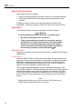
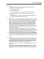
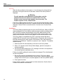
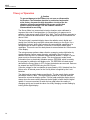
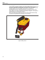
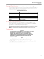
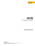
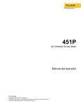
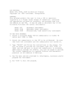
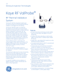
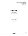
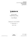
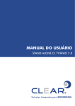
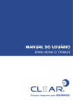
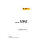
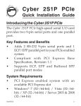
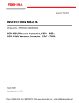
451P Ion Chamber Survey Meter Operators Manual PN FBC-0059 September 2013, Rev. 1 © 2013 Fluke Corporation. All rights reserved. Specifications are subject to change without notice. All product names are trademarks of their respective companies. Warranty and Product Support Fluke Biomedical warrants this instrument against defects in materials and workmanship for one full year from the date of original purchase. During the warranty period, we will repair or, at our option, replace at no charge a product that proves to be defective, provided you return the product, shipping prepaid, to Fluke Biomedical. This warranty does not apply if the product has been damaged by accident or misuse or as the result of service or modification by other than Fluke Biomedical. IN NO EVENT SHALL FLUKE BIOMEDICAL BE LIABLE FOR CONSEQUENTIAL DAMAGES. Only serialized products and their accessory items (those products and items bearing a distinct serial number tag) are covered under this one-year warranty. PHYSICAL DAMAGE CAUSED BY MISUSE OR PHYSICAL ABUSE IS NOT COVERED UNDER THE WARRANTY. Items such as cables and nonserialized modules are not covered under this warranty. Recalibration of instruments is not covered under the warranty. This warranty gives you specific legal rights, and you may also have other rights which vary from state to state, province to province, or country to country. This warranty is limited to repairing the instrument to Fluke Biomedical’s specifications. Contents (continued) Notices All Rights Reserved Copyright 2013, Fluke Biomedical. No part of this publication may be reproduced, transmitted, transcribed, stored in a retrieval system, or translated into any language without the written permission of Fluke Biomedical. Copyright Release Fluke Biomedical agrees to a limited copyright release that allows you to reproduce manuals and other printed materials for use in service training programs and other technical publications. If you would like other reproductions or distributions, submit a written request to Fluke Biomedical. Unpacking and Inspection Follow standard receiving practices upon receipt of the instrument. Check the shipping carton for damage. If damage is found, stop unpacking the instrument. Notify the carrier and ask for an agent to be present while the instrument is unpacked. There are no special unpacking instructions, but be careful not to damage the instrument when unpacking it. Inspect the instrument for physical damage such as bent or broken parts, dents, or scratches. Technical Support For application support or answers to technical questions, either email [email protected] or call 1-800- 8504608 or 1-440-248-9300. In Europe, email [email protected] or call +31-40-2965314. Claims Our routine method of shipment is via common carrier, FOB origin. Upon delivery, if physical damage is found, retain all packing materials in their original condition and contact the carrier immediately to file a claim. If the instrument is delivered in good physical condition but does not operate within specifications, or if there are any other problems not caused by shipping damage, please contact Fluke Biomedical or your local sales representative. Returns and Repairs Return Procedure All items being returned (including all warranty-claim shipments) must be sent freight-prepaid to our factory location. When you return an instrument to Fluke Biomedical, we recommend using United Parcel Service, Federal Express, or Air Parcel Post. We also recommend that you insure your shipment for its actual replacement cost. Fluke Biomedical will not be responsible for lost shipments or instruments that are received in damaged condition due to improper packaging or handling. Use the original carton and packaging material for shipment. If they are not available, we recommend the following guide for repackaging: Use a double–walled carton of sufficient strength for the weight being shipped. Use heavy paper or cardboard to protect all instrument surfaces. Use nonabrasive material around all projecting parts. Use at least four inches of tightly packed, industry-approved, shock-absorbent material around the instrument. Returns for partial refund/credit: Every product returned for refund/credit must be accompanied by a Return Material Authorization (RMA) number, obtained from our Order Entry Group at 1-440-498-2560. Repair and calibration: To find the nearest service center, go to www.flukebiomedical.com/service or In the U.S.A.: Cleveland Calibration Lab Tel: 1-800-850-4608 x2564 Email: [email protected] Everett Calibration Lab Tel: 1-888-99 FLUKE (1-888-993-5853) Email: [email protected] In Europe, Middle East, and Africa: Eindhoven Calibration Lab Tel: +31-40-2675300 Email: [email protected] In Asia: Everett Calibration Lab Tel: +425-446-6945 Email: [email protected] To ensure the accuracy of the Product is maintained at a high level, Fluke Biomedical recommends the product be calibrated at least once every 12 months. Calibration must be done by qualified personnel. Contact your local Fluke Biomedical representative for calibration. Certification This instrument was thoroughly tested and inspected. It was found to meet Fluke Biomedical’s manufacturing specifications when it was shipped from the factory. Calibration measurements are traceable to the National Institute of Standards and Technology (NIST). Devices for which there are no NIST calibration standards are measured against inhouse performance standards using accepted test procedures. WARNING Unauthorized user modifications or application beyond the published specifications may result in electrical shock hazards or improper operation. Fluke Biomedical will not be responsible for any injuries sustained due to unauthorized equipment modifications. Restrictions and Liabilities Information in this document is subject to change and does not represent a commitment by Fluke Biomedical. Changes made to the information in this document will be incorporated in new editions of the publication. No responsibility is assumed by Fluke Biomedical for the use or reliability of software or equipment that is not supplied by Fluke Biomedical, or by its affiliated dealers. Manufacturing Location The 451P Ion Chamber Survey Meter is manufactured at Fluke Biomedical, 6920 Seaway Blvd., Everett, WA, U.S.A. Table of Contents Title Introduction ............................................................................................ Intended Use ......................................................................................... Safety Information ................................................................................. Features ................................................................................................ Overrange Rate ................................................................................. Low Battery Indicator ......................................................................... Warm-up Time ................................................................................... Specifications ........................................................................................ Receiving Inspection ............................................................................. Operation ............................................................................................... External Controls ............................................................................... ON/OFF Button .............................................................................. MODE Button ................................................................................ Freeze Mode ................................................................................. Integrate Mode .............................................................................. Self Test ........................................................................................ Installation ......................................................................................... Operational check.............................................................................. Optional Check Source Use .............................................................. Theory of Operation .............................................................................. Maintenance .......................................................................................... Routine Cleaning ............................................................................... Storage .............................................................................................. Battery Replacement ......................................................................... Replaceable Parts Information .......................................................... Recalibration and Service Information............................................... Troubleshooting ................................................................................. i Page 1 1 2 5 5 5 5 6 10 10 10 10 11 11 11 12 12 13 13 14 16 16 17 17 19 19 19 451P Operators Manual ii List of Tables Table 1. 2. 3. Title Page Symbols..................................................................................................... 2 Bar Graph Display Update Periods ........................................................... 15 Replaceable Parts List .............................................................................. 19 iii 451P Operators Manual iv List of Figures Figure Title 1. 2. 3. 4. 5. 6. Fluke 451P Ion Chamber Survey Meter .................................................... Model 451P Typical Energy Response ..................................................... Model 451P DE SI Typical Energy Dependence ....................................... Survey Meter Angular Response .............................................................. Location of RS-232 port ............................................................................ Battery Access .......................................................................................... v Page 4 7 8 9 13 18 451P Operators Manual vi Introduction The Model 451P Ion Chamber Survey Meter (the Survey Meter) is a hand-held, pressurized, battery operated meter designed to measure gamma and x-ray radiation above 25 keV, and beta radiation above 1 MeV, using the latest CMOS and LCD technology. The Survey Meter case is constructed of high strength ABS plastic. A gasket seals moisture out of the Survey Meter and provides a cushion for the internal components. The readout consists of a 2½ digit liquid crystal display and a 100 segment analog bar graph. The bar graph contains a zero segment and twenty groups of five segments each. A permanent scale is located on the display screen. The major divisions of the scale indicate the units corresponding to the range that the meter is measuring. The units of measurement show next to the 2½ digit display. LOW BAT and FREEZE appear on the display when the Survey Meter is operating in these modes. External controls consist of an ON/OFF button and a MODE button. The Survey Meter is auto-ranging and auto-zeroing. The auto-on circuit for the backlight is enabled when twilight conditions occur. An internal factory-set alarm blinks the display if the rate exceeds 5 R/hr. Two 9 volt batteries, located in the rear of the Survey Meter, provide over 200 hours of continuous operation. Intended Use The 451P Ion Chamber Survey Meter is a hand-held, pressurized, battery operated unit designed to measure gamma and x-ray radiation above 25 keV and beta radiation above 1 MeV. 1 451P Operators Manual Safety Information A Warning identifies conditions and procedures that are dangerous to the user. A Caution identifies conditions and procedures that can cause damage to the Product or the equipment under test. Table 1 is a list of symbols used on the product and in this manual. Table 1. Symbols Symbol Description Symbol Description Hazardous voltage. Risk of electric shock. Risk of Danger. Important information. See Manual. DC (Direct Current) On/Off button This product complies with the WEEE Directive (2002/96/EC) marking requirements. The affixed label indicates that you must not discard this electrical/electronic product in domestic household waste. Product Category: With reference to the equipment types in the WEEE Directive Annex I, this product is classed as category 9 "Monitoring and Control Instrumentation" product. Do not dispose of this product as unsorted municipal waste. Go to Fluke’s website for recycling information. Conforms to European Union directives This product contains a Lithium-ion battery. Do not mix with solid waste stream. Spent batteries should be disposed of by a qualified recycler or hazardous materials handler per local regulations. Contact your authorized Fluke Service Center for recycling information. Warning To prevent possible electrical shock, fire, or personal injury: 2 • Read all safety information before you use the Product. • Use the Product only as specified, or the protection supplied by the Product can be compromised. • Remove the batteries if the Product is not used for an extended period of time, or if stored in temperatures above 50 °C. If the batteries are not removed, battery leakage can damage the Product. Ion Chamber Survey Meter Safety Information • The battery door must be closed and locked before you operate the Product. • Replace the batteries when the low battery indicator shows to prevent incorrect measurements. • Comply with local and national safety codes. Use personal protective equipment. • Carefully read all instructions. • Do not touch voltages > 30 V ac rms, 42 V ac peak, or 60 V dc. • Do not use the Product around explosive gas, vapor, or in damp or wet environments. • Do not use and disable the Product if it is damaged. • Do not use the Product if it operates incorrectly. • Examine the case before you use the Product. Look for cracks or missing plastic. • Use this Product indoors only. • Remove all accessories before the battery door is opened. • If the device shows a relatively high radiation rate, it is possible that the Product was contaminated. Be careful when you replace or work on this Product. High radiation rates can quickly cause the cumulative exposure of the operator to increase, which increases the risk of injury. • The check source contains radioactive materials, used for the verification of the survey meter operation. Be careful when you use and store the check source. 3 451P Operators Manual • Each person who uses a product that senses and measures ionizing radiation must: o Be approved to do work where there is radiation o Obey all applicable safety procedures and regulations o Be approved to correctly interpret the indications on the product The user of this Product must read and strictly obey the instructions and precautions contained in the manuals. If you do not obey the instructions and precautions, there is a risk of injury. If you do not obey the instructions and precautions there is a risk that the Product will show incorrect indications. Before each use, do a battery check and other preoperational checks to make sure that the Product operates correctly. hms01.eps Figure 1. Fluke 451P Ion Chamber Survey Meter 4 Ion Chamber Survey Meter Features Features The following sections describe the features of the Survey Meter. Overrange Rate If the instantaneous radiation rate measured by the Survey Meter exceeds 5 R/h, the 'R' in 'mR/h' or the 'Sv' in 'Sv/h' displayed will blink to notify the user that a potential error in the integrated radiation value exists. The blinking will stop when the integrated value is cleared. This, however, may also clear the log data RAM. Low Battery Indicator There are about 6 hours of operation remaining when the LOW BATTERY indicator first becomes visible. When the LOW BATTERY indicator blinks, there is less than 1 hour of operation remaining. These times are for two batteries installed and from the first occurrences of these indications. If the Survey Meter is turned off during a low battery condition, the batteries will recover somewhat, but time of operation remaining will be less. The LCD low battery indicator is disabled during communication mode. Be sure to use fresh batteries when calibrating the Survey Meter. Warning For safe operation and maintenance of the product, note the chamber bias from the self-test. If chamber bias is LO, the Product cannot measure high radiation rates accurately. The Product requires service, contact Fluke. Verify the chamber bias is low. Turn off the Survey Meter and replace with new 9 volt batteries. Turn on the Survey Meter. After the self-test, if blinking low battery reoccurs, the bias is low. Warm-up Time The pressured ion chamber collection potential is 105 Vdc and is derived from the 5 lithium cells. The warm-up time for a Survey Meter that has been off 12 hours or more is about 4 minutes for readings less than 20 °R/h in a 10 μR/h or less background. 5 451P Operators Manual Specifications Radiation Detected ............................................... Beta above 1 MeV & gamma above 25 KeV Operating Ranges ................................................. 0 μR/hr to 500 μR/hr (0 μSv/h to 5 μSv/h), 0 mR/h to 5 mR/h (0 μSv/h to 50 μSv/h) 0 mR/h to 50 mR/h (0 μSv/h to 500 μSv/h), 0 mR/h to 500 mR/h (0 mSv/h to 5 mSv/h), 0 R/h to 5 R/h (0 mSv/h to 50 mSv/h) Accuracy ................................................................ ± 10 % of reading between 10 % and 100 % of full-scale indication on any range, exclusive of energy response (calibration source is 137 Cs) Detector ................................................................. 230 cc active volume air ionization chamber, pressurized to 8 atmospheres. Plastic chamber wall 200 mg/cm2 thick Warm-Up Time....................................................... Less than one minute for initial operation when the instrument is in temperature equilibrium with the surrounding area and about 4 minutes for readings less than 20 μR/h in a 10 μR/h or less background. Drift......................................................................... After seven minutes operation, 0.04 mR/h equivalent, or less Response Time ..................................................... Time measured from 10 % to 90 % of final value for a step increase/decrease in radiation rate such that a range change does not occur: 0 μR/h to 500 μR/h (0 μSv/h to 5 μSv/h) range: 5 seconds. 0 mR/hr to 5 mR/hr (0 μSv/h to 50 μSv/h) range: 2 seconds. 0 mR/h to 50 mR/h (0 μSv/h to 500 μSv/h) range: 1.8 seconds. 0 mR/h to 500 mR/h (0 mSv/h to 5 mSv/h) range: 1.8 seconds. 0 R/h to 5 R/h (0 mSv/h to 50 mSv/h) range: 1.8 seconds. NOTE: In pulsating field, the instantaneous rate should not exceed 5 R/h for proper integration; instantaneous exposure rate is still limited to 5 R/h Precision ................................................................ Within 5 % reading Readout.................................................................. Liquid Crystal Display: contains an analog bar graph with a permanent scale on the display and a 2½ digit display. Analog Display: the bar graph consists of 100 segments, 2½ inches long; the scale has five major divisions; the appropriate value for the operating range of the instrument will appear below the scale. Digital Display: the digital display is 2½ digits followed by a significant zero digit depending on the operating range of the instrument. The leading ½ digit is blank, or a “1” or a “0” for clarity. Units of measure appear to the right of the digital display. Appropriate multipliers also appear on the display Units: as indicated under Range, programmable in R/h or Sv/h. Appropriate multipliers also appear on the display. Auto-On Backlight: turns on when ambient light is less then twilight conditions. External Controls .................................................. ON/OFF button, MODE button Automatic Features .............................................. Ranging and zeroing are fully automatic. 6 Ion Chamber Survey Meter Specifications Environmental ....................................................... Operating Temperature Range: -4 °F to +122 °F (-20 °C to +50 °C) Relative Humidity Range: 0 % to 95 %, non-condensing Geotropism: less than 1 % Altitude 2000 m For Indoor Use Dimensions (L x W x H) ........................................ 8.5 in x 4.5 in x 8.6 in (21 cm x 11.4 cm x 21.3 cm) Weight .................................................................... Approximately 2.6 lb (1.2 kg) Batteries................................................................. Two 9-volt batteries (NEDA 1604A or 6LR61 or 6AM6) provide over 200 hours continuous operation. IP Rating ................................................................ IEC 60529: IP40 Safety ..................................................................... IEC 61010-1: Pollution Degree 2 Electromagnetic Environment ............................. IEC 61326-1: Portable Emissions Classification...................................... IEC CISPR 11: Group 1, Class A. Group 1 ISM equipment: group 1 contains all ISM equipment in which there is intentionally generated and/or used conductively coupled radio-frequency energy which is necessary for the internal functioning of the equipment itself. Class A equipment is equipment suitable for use in all establishments other than domestic and those directly connected to a low voltage power-supply network which supplies buildings used for domestic purposes. * Specifications are subject to change without notice. 1.4 Relative Response 1.2 1 0.8 Side Face Front 0.6 0.4 0.2 0 10 10 0 10 0 0 10 0 0 0 Energy (keV) Figure 2. Model 451P Typical Energy Response hms06.eps 7 451P Operators Manual Dose equivalent units were determined using conversion coefficients at H*(10), found in I CRU 47, April, 1992. 1.4 Relative Response 1.2 1 0.8 Side Front 0.6 0.4 0.2 0 10 100 1000 100 00 Energy (keV) Figure 3. Model 451P DE SI Typical Energy Dependence 8 hms05.eps Ion Chamber Survey Meter Specifications 0° 1.0 20° .9 40° .8 .7 .6 60° .5 .4 .3 .2 80° .1 90° 100° 38 keV 120° 137Cs 140° 180° 160° hms04.eps Figure 4. Survey Meter Angular Response 9 451P Operators Manual Receiving Inspection Upon receipt of the Survey Meter: 1. Check the shipping cartons(s) and their contents for in-shipment damage. 2. Check that all items listed on the packing slip are present and in good condition. If damage is evident, make a claim with the carrier and contact Fluke immediately. If items are missing, contact Fluke. See How to Contact Fluke. Operation The following sections describe the operation of the Survey Meter. Warning To prevent possible electrical shock, fire, or personal injury: • Do not put metal objects into connectors. • Fluke recommends that you wait for a one-minute warm-up period before you make a measurement. If the Survey Meter experiences a very large temperature change (for example, it moves indoors from outside) a longer warm-up period can be necessary to measure a value less than 50 μR/h. External Controls There are two external controls on the Survey Meter: and ON/OFF button and a MODE button. ON/OFF Button Press the ON/OFF button to turn on the Survey Meter. All the elements in the display turn on and the microprocessor runs through an initialization procedure. Part of the procedure includes reading the calibration coefficients stored in EEPROM. If an EEPROM read error occurs, an error code (E1) displays at power-on and unity calibration coefficients are used. The bar graph and digital display will show a reading that decreases as the Survey Meter stabilizes. The initial reading usually starts in the 5 R/h range and decreases through the lower ranges to a reading of less than 50 μR/h within 120 seconds. When the elements in the display turn off, with the exception of those necessary for normal operation, the user can begin the measurement process. Note Background fluctuations may occur (less than 50 μR/h) returning to original reading typically in less than 3 seconds. 10 Ion Chamber Survey Meter Operation MODE Button To configure the MODE button to the opposite function without a RS-232 connection, use the following procedure: 1. Turn off the Survey Meter. 2. Press the MODE button. 3. Turn on the Survey Meter while continuing to press the MODE button. 4. Release the MODE button when the display is in the “all elements on” condition. 5. Use the MODE button to toggle the Survey Meter between the Rate mode and the newly selected Freeze or Integrate mode. Freeze Mode When configured to select the Freeze mode, the MODE button acts as a toggle switch. Press the button until FREEZE appears on the display. Operation in the Freeze mode gives the user a constant reference of the highest exposure rate obtained from the time the freeze function is initialized. The highest reading appears as a single bar on the bar graph. The current reading continues to display on the digital display and the bar graph. If a measurement is obtained which exceeds the freeze bar reading, the freeze bar moves to the higher measurement point. The operating range of the Survey Meter remains locked on the highest range attained during the Freeze mode so that the scale and the multiplier remain the same. For example, assume the scale units appear as 10, 20, 30, 40, 50, and the freeze bar is at 47 mR/h on the bar graph. If the Survey Meter then measures a radiation field of 120 mR/h, the scale units will change to 100, 200, 300, 400, 500 and the freeze bar appears on the graph at 120 mR/h. If the Survey Meter measurement goes below 100 mR/h, the units on the scale will not change until the Survey Meter is taken out of the Freeze mode. However, the digital display continues to show the current reading. The Survey Meter operates in the Freeze mode until the user toggles the MODE button to return to the normal operating mode. Integrate Mode The Integrate mode is operational 30 seconds after the Survey Meter is turned on and all of the time after that. However, the integrated exposure displays only when the MODE button has been configured as a toggle to display exposure rate/integrated exposure. If the MODE button is pressed within the 30 second initialization period of the Survey Meter, the display will read “0”. When integration starts, “0.0 μR” displays. Toggle MODE to read exposure rate as required. To reset the integration display, toggle the display from the Rate mode to the Integrate mode. Keep the MODE button pressed for approximately 5 seconds. The display will clear, and then read “0.0 μR.” Exposures are accumulated up to 99 R. 11 451P Operators Manual Self Test When the Survey Meter is first turned on, it runs through a functional self-test procedure. During this self-test, the firmware version of the Survey Meter is displayed. Warning For safe operation and maintenance of the product, note the chamber bias from the self-test. If chamber bias is LO, the Product cannot measure high radiation rates accurately. The Product requires service, contact Fluke. If the Survey Meter passes the self-test, it goes into the normal operating mode. If the Survey Meter fails the self-test, it remains locked with the firmware revision displayed. Contact Fluke for corrective action. See the How to Contact Fluke section. Installation The Survey Meter periodically tests for input at its RS-232 port. When an RS-232 signal is detected, the Survey Meter sends test signals using its sending device and, if RS-232 is present and operational, the Survey Meter enters into the communications mode. The Survey Meter display clears and the letters “CO” display as an indication that the Survey Meter is in the communications mode. The Survey Meter is compatible with a CRT or printing terminal that has a standard RS-232 connector and a 1200-baud rate. A computer with a modem or terminal emulator can be used in place of the terminal. Set up the terminal or computer for a 1200 baud, 7 data bits, no parity bit, and 1 stop bits. To establish communications: 1. Attach the RS-232 cable assembly to the back of the Survey Meter. 2. When “CO” appears on the Survey Meter display, press the computer or terminal spacebar. 3. If the Survey Meter displays the “CO” message, but there is no response at the terminal press the spacebar twice. If there is a problem getting the communications message (CO) to be displayed on the Survey Meter: 1. Be sure the computer communication port is active. The Survey Meter communication transmitter/RCR pair is active when it detects a negative mark voltage at the receiver input. (CO) then appears on the Survey Meter display. 2. Press space bar twice. If there is still a problem, contact Fluke for further instructions. See the How to Contact Fluke section in this manual. 12 Ion Chamber Survey Meter Operation RS-232 Figure 5. Location of RS-232 port hms03.eps Operational check Fluke recommends an operational check upon receipt of the Survey Meter and before each use. Monitor the start sequence. These results indicate the device is operating correctly: • There are no error messages in the startup sequence. • The display does not freeze (showing only the firmware number). • The Survey Meter gets to the background level within 2 minutes. Optional Check Source Use For more testing use the check source (Fluke part number: 3463380). To check the device, do the following: 1. Turn on and initialize Survey Meter. 2. After the self-test completes, wait for 1 minute. 3. Place check source on the white dot on the right hand side of the case. 4. Hold source in position until reading stabilizes and then record the reading. This is your baseline measurement. Perform all subsequent operational checks in the same manner with the source in the same position. Each subsequent check source measurement should be within 30 % of the recorded baseline measurement. 13 451P Operators Manual Theory of Operation Caution To prevent damage to the Product, do not open or disassemble the Product. The ionization chamber is pressurized and sealed at the factory, because the high impedance circuits of the ion chamber are easily contaminated with grease and dirt that produce electrical leakage. The ion chamber cannot be disassembled for servicing. The Survey Meter is a pressurized ionization chamber meter calibrated in exposure rate units of roentgens/hour (or Sieverts/hour) for gamma and xradiation in the energy range of 20 keV to 2 MeV. The Survey Meter responds to, but is not calibrated for beta radiation. Beta energies that can be measured are above 1 MeV. The liquid crystal, supertwist display shows the radiation rate in digital and analog form with the range multiplier values also showing on the scale. It is a lightweight electronic device that requires the computational capabilities of a microprocessor to make it operate. It functions in a multiplex mode called quadriplex. This mode uses four back-planes to accommodate the 128 elements of the display. The microprocessor performs data collection, averaging, and multiplication by stored calibration factors, range changing, and battery check functions, in addition to driving the LCD. Between computational periods, it “sleeps” in a low power mode to conserve battery power. The microprocessor reads stored information from an electrically erasable memory, EEPROM, which is used by the program for calibration and display units. The EEPROM will retain stored data when the Survey Meter is OFF or when the batteries are removed. Data can be entered into the EEPROM using the RS-232 port. Collection voltage for the ion chamber is approximately 105 V obtained from five lithium cells. All internal power for the Survey Meter is supplied by the 9 volt batteries. The digital and bar graph displays read directly. The bar graph display update periods are listed in Table . The digital display updates at 1 second intervals nearest the current bar display update. The bar graph and digits display do not always show the same reading because the bar graph is faster than the digital update. It is more convenient to watch the bar graph when the reading is changing quickly and to read the value of a slowly changing or static reading by looking at the digital display. 14 Ion Chamber Survey Meter Theory of Operation The bar graph display is a digital presentation, programmed to appear as a linear analog meter display. It is also referred to as the analog display throughout this manual. Table 2. Bar Graph Display Update Periods Range Update Period 5 R/h (50 mSv/h) 0.05 second 500 mR/h (5 mSv/h) 0.05 second 50 mR/h (500 μSv/h) 0.05 second 5 mR/h (50 μSv/h) 0.05 second 500 μR/h (5 μSv/h) 0.15 second There are 20 bars between each major division. The numerical values of the five major divisions change appropriately for the range in which the Survey Meter is operating. For instance, the first major division would have the numeric value of 1, 10 or 100. The minor divisions are worth 0.05, 0.5 or 5. The incremental nature of both the digital reading and the analog bar graph provide greater accuracy for reading in different portions of the scale. For example, on the 0 mR/h to 5 mR/h range, with a digital reading of 2.0 and above, the analog bar graph can be read more accurately than the digital display. Below a digital reading of 2.0, the digital display is more accurate because it consists of three significant digits. The stated precision of the digital display is accurate only above a reading of 5 % of the full scale. Note The same analysis applies to all the other ranges because the number of significant digits or active bar elements are independent of the position of the decimal point or the unit’s multiplier. There is a small hysteresis built into the range changing circuit so that the Survey Meter does not keep changing scales if the reading is at the threshold of range change. It is important in calibration of the Survey Meter that the calibration coefficients track from range to range because an oscillatory condition can occur if the calibration on a given range is low and the coefficient for the next more sensitive range is high. The program in the Survey Meter ROM is proprietary to Fluke. The firmware version appears in the digital part of the LCD display (prior to the “all elements on” display) when the Survey Meter is turned on. The firmware program consists of three main parts: operation, communication, and monitoring. 15 451P Operators Manual The operation portion of the firmware performs all of the control functions needed to read and control the electrometer and range change amplifier, calculate radiation rate, and display the calculated values on the LCD Display. In addition, the measured data are smoothed and displayed in an exponential manner with time that simulates the rise and fall time of an ordinary meter display. Range changing is performed automatically. If a large increase in signal is detected, the range changing skips to higher ranges bypassing exponential rise with time to get to the new reading quickly. The Survey Meter continually integrates the detected radiation signal and saves the accumulated amount that may be read by the operator at any time. The operator may also reset the integration process. When the RS-232 cable is attached to the Survey Meter, the Survey Meter detects its presence and runs the communications portion of the program. The communication parameters are 1200, N, 7, and 1. Serial communications are performed in software rather than using a hardware device. The operation program can be run from communications in the Test mode. Maintenance Very little maintenance is required for the Survey Meter, but some periodic attention may be necessary, especially if the Survey Meter is used in harsh industrial conditions. Warning To prevent possible electrical shock, fire, or personal injury: • Do not operate the Product with covers removed or the case open. Hazardous voltage exposure is possible. • Use only specified replacement parts. • Have an approved technician repair the Product. • Only assemble and operate high-pressure systems if you know the correct safety procedures. High-pressure liquids and gases are hazardous and the energy from them can be released without warning. • Many components on the printed circuit board are static sensitive. Obey all ESD precautions when you touch the printed circuit board assembly. Routine Cleaning Do not immerse the Survey Meter. The Survey Meter is not waterproof; liquid could damage the circuits. The Survey Meter should be kept clean and free from dirt and contamination. To clean the Survey Meter, wipe with a damp cloth using any commercially available cleaning or decontaminating agent. 16 Ion Chamber Survey Meter Maintenance Storage Storage of Fluke Biomedical instruments must comply with Level B storage requirements as outlined in ANSI N45.2.2 (1972), Section 6.1.2 (.2). The storage area shall comply with ANSI N45.2.2 (1972), Section 6.2 Storage Area, paragraphs 6.2.1 through 6.2.5. Housekeeping shall conform to ANSI N45.2.3 (1972). Level B components must be stored within a fire resistant, tear resistant, weather tight enclosure, in a well-ventilated building or equivalent. Storage of Fluke Biomedical instruments must comply with the following considerations: 1. Inspection and examination of items in storage must be in accordance with ANSI N45.2.2 (1972), Section 6.4.1. 2. Requirements for proper storage must be documented and written procedures, or instructions shall be established. 3. In the event of a fire, post-fire evaluation must be in accordance with ANSI N45.2.2 (1972), Section 6.4.3. 4. Removal of items from storage must be in accordance with ANSI N45.2.2 (1972), Sections 6.5 and 6.6. Battery Replacement Warning To prevent possible electrical shock, fire, or personal injury: • Batteries contain hazardous chemicals that can cause burns or explode. If exposure to chemicals occurs, clean with water and get medical aid. • Do not disassemble the battery. • Repair the Product before use if the battery leaks. • Be sure that the battery polarity is correct to prevent battery leakage. • Do not short the battery terminals together. • Do not disassemble or crush battery cells and battery packs. • Do not keep cells or batteries in a container where the terminals can be shorted. • Do not put battery cells and battery packs near heat or fire. Do not put in sunlight. • Do not operate the Product with covers removed or the case open. Hazardous voltage exposure is possible. • This Product contains lithium cells with a potential voltage of 105 V on the battery assembly. To prevent personal injury or damage to the Product, be careful with this assembly during removal and installation. 17 451P Operators Manual The LOW BAT message will appear on the display approximately 6 hours prior to the Survey Meter becoming inoperable. To ensure that the Survey Meter operates to specification, change the batteries within 4 hours after the LOW BAT message appears. The Survey Meter will function on one battery for approximately 100 hours, allowing replacement of one battery at a time if the Survey Meter must remain operational during battery changeover. Use regular or alkaline batteries for replacement purposes. Both 9 volt batteries are located in the rear of the Survey Meter and are easily accessible and replaceable with the battery cover removed. hms02.eps Figure 6. Battery Access 18 Ion Chamber Survey Meter Maintenance Replaceable Parts Information Fluke maintains a complete inventory of all normal replaceable parts. To place an order, or to obtain information concerning replaceable parts, contact Fluke. See the How to Contact Fluke section in this manual. Table 3. Replaceable Parts List Part Number Description 3567752 Keypad Overlay, Red 3567765 Handle, Yellow 3567776 Handle, Foam Grip, Black 3463380 Check source, CS-137, 10 UCI, Flat disc, 1-inch diameter 614487 Battery, 9 V, Alkaline Recalibration and Service Information Fluke recommends a once yearly calibration on your Survey Meter. If your Survey Meter needs recalibration or repair, we request that you contact Fluke. See the How to Contact Fluke section in this manual. More information concerning the operation, application, or service of your Survey Meter can be obtained from the applications engineer at the numbers listed above. Troubleshooting Caution For safe operation and maintenance of the Product, use caution when working on this Product. If the device indicates a relatively high radiation rate, there is a possibility that the Product has been contaminated. High rates can quickly cause the operator’s cumulative exposure to increase with the potential for injury. Note Install fresh batteries prior to performing any calibration on the Survey Meter. If the Survey Meter fails self-test, it will remain locked on the firmware revision number. See the How to Contact Fluke section. 19 451P Operators Manual 20