1
ELECTROSURGICAL UNIT ANALYZER ESU-2400 Series USER MANUAL BC BIOMEDICAL ESU-2400 SERIES TABLE OF CONTENTS WARNINGS, CAUTIONS, NOTICES ........................................................................... iv DESCRIPTION ............................................................................................................. 1 Accessories .............................................................................................................. 3 OVERVIEW .................................................................................................................... 6 TYPICAL MEASUREMENT CONNECTIONS ................................................................. 7 Monopolar ................................................................................................................. 7 Bipolar........................................................................................................................ 8 External Loads ........................................................................................................... 9 Tissue Response Test ............................................................................................. 11 Leakage Mode 1a .................................................................................................... 12 Leakage Mode 1b .................................................................................................... 13 Leakage Mode 2 ...................................................................................................... 14 Leakage Mode 3 ...................................................................................................... 15 GETTING STARTED ForceTriad™ Preventative Maintenance.................................................................. 16 Measure RF Energy Scenario 1: Measure mA, 500 ohm load, manual DUT trigger .............................. 17 Scenario 2: Measure mA and Watts, 300 ohm load, footswitch triggers DUT ....... 19 Scenario 3: Measure Hyfrecator mA, 200 ohm load, manual DUT trigger ............ 22 Scenario 4: Measure mA and kHz, 200 ohm load, manual DUT, Pulse Mode 1 ... 24 Scenario 5: Measure V, Delayed Mode ................................................................. 27 Measure RF Leakage Leakage Test 1a: Active to Ground ....................................................................... 30 Leakage Test 1b: Dispersive to Ground ................................................................ 32 Leakage Test 2: Ground Referenced DUT, Active to Ground ............................... 34 Leakage Test 3: Ground Referenced DUT, Dispersive to Ground ........................ 36 REM/ARM/CQM Test Scenario 1: Test REM at 35 ohms ........................................................................ 38 Scenario 2: Increase REM by 40% ....................................................................... 39 i Load Curves Scenario 1: Bipolar, 60W, 100 to 1000 ohms, auto trigger DUT............................ 40 Scenario 2: Pure Cut, 300W, Load List, manual trigger DUT ................................ 43 Autosequence RF Measure: 200 ohms, 315mA Limit, ±10mA ...................................................... 46 Load Curve: Pure Cut, 300W, 50-5000 ohms, Manual Trigger ............................. 49 Auto CQM ............................................................................................................. 51 MAIN SCREEN ............................................................................................................. 53 AUTOSEQUENCES ...................................................................................................... 56 Running the Autosequence ................................................................................ 73 Autosequence Results ....................................................................................... 77 MEASURE RF ENERGY .............................................................................................. 78 Tissue Response Test ........................................................................................ 79 Parameter Descriptions ...................................................................................... 81 Graph Screen .................................................................................................... 84 Footswitch Configuration .................................................................................... 87 ESU-2400H Advanced Input Modes ................................................................... 89 POWER LOAD CURVES ............................................................................................. 97 REM/ARM/CQM ......................................................................................................... 104 MEASURE RF LEAKAGE .......................................................................................... 105 SYSTEM TOOLS ....................................................................................................... 112 Transfer Files.................................................................................................... 112 Time and Date Setup ....................................................................................... 113 Touchscreen Calibration .................................................................................. 114 System Setup .................................................................................................. 115 System Version and Updates .......................................................................... 116 Networking....................................................................................................... 121 Remote Mode ................................................................................................... 122 Internet Access ................................................................................................ 124 RS-232 Terminal .............................................................................................. 124 ii COMMON DIALOG SCREENS .................................................................................. 126 File Open ......................................................................................................... File Save ......................................................................................................... Keypad ............................................................................................................ Numpad ........................................................................................................... Print ................................................................................................................. 126 127 128 129 130 KEYBOARD / MOUSE ............................................................................................... 133 BARCODE SCANNER ............................................................................................... 133 ERROR MESSAGES ................................................................................................. 134 SYSTEM INPUTS AND OUTPUTS ............................................................................ 137 DFA® TECHNOLOGY ............................................................................................... 139 FOOTSWITCH CONNECTOR .................................................................................... 140 COMMUNICATION PROTOCOL ................................................................................ 141 COMMUNICATION COMMAND SUMMARY .............................................................. 148 FREQUENTLY ASKED QUESTIONS (FAQ) .............................................................. 152 MANUAL REVISIONS ................................................................................................ 154 LIMITED WARRANTY................................................................................................ 154 SPECIFICATIONS ..................................................................................................... 156 NOTES ....................................................................................................................... 161 iii WARNING - USERS The ESU-2400 Series is for use by skilled technical personnel only. WARNING - USE The ESU-2400 Series is intended for testing only and should never be used in diagnostics, treatment or any other capacity where it would come in contact with a patient. WARNING - USE Never touch exposed metal surfaces on test leads or other current-carrying parts while the DUT is activated. WARNING - MODIFICATIONS The ESU-2400 Series is intended for use within the published specifications. Any application beyond these specifications or any unauthorized user modifications may result in hazards or improper operation. WARNING - CONNECTIONS All connections to patients must be removed before connecting the DUT to the ESU-2400 Series. A serious hazard may occur if the patient is connected when testing with the ESU-2400 Series. Do not connect any leads from the patient directly to the ESU-2400 Series or DUT. WARNING - POWER ADAPTOR Unplug the Power Adaptor before cleaning the surface of the ESU-2400 Series. iv WARNING - LIQUIDS Do not submerge or spill liquids on the ESU-2400 Series. Do not operate the ESU-2400 Series if internal components not intended for use with fluids may have been exposed to fluid, as the internal leakage may have caused corrosion and be a potential hazard. v CAUTION - SERVICE The ESU-2400 Series is intended to be serviced only by authorized service personnel. Troubleshooting and service procedures should only be performed by qualified technical personnel. CAUTION - ENVIRONMENT Exposure to environmental conditions outside the specifications can adversely affect the performance of the ESU-2400 Series. Allow ESU2400 Series to acclimate to specified conditions for at least 30 minutes before attempting to operate it. CAUTION - CLEANING Do not immerse. The ESU-2400 Series should be cleaned by wiping gently with a damp, lint-free cloth. A mild detergent can be used if desired. CAUTION - INSPECTION The ESU-2400 Series should be inspected before each use for wear and the ESU-2400 Series should be serviced if any parts are in question. CAUTION - VENTILATION The ESU-2400 Series includes ventilation slots to help prevent overheating during operation and should not be blocked. vi NOTICE – CE The ESU-2400 Analyzers bear the mark Based on the following testing standards: ELECTROMAGNETIC COMPATIBILITY DIRECTIVE EN 61326-1:2005 (EN61326-1:2006) “Electrical equipment for measurement, control and laboratory use – EMC requirements” This equipment has been type tested by an independent, accredited testing laboratory and compliance was demonstrated to the above standard to the extent applicable. EMISSIONS Radiated and Line Conducted Emissions EN 61000-3-2 EN 61000-3-3 Harmonic Current Emissions Voltage Fluctuation and Flicker IMMUNITY– CLASS C EN 61000-4-2 EN 61000-4-3 EN 61000-4-4 EN 61000-4-5 EN 61000-4-6 EN 61000-4-11 Electrostatic Discharge Radiated Electric Field Immunity Electrical Fast Transients / Bursts Surge Voltage Conducted Disturbance Voltage Dips and Short Interrupts LOW VOLTAGE DIRECTIVE EC – Directive 73/23/EC EN 61010-1:2001 “Safety requirements for electrical equipment for measurement, control, and laboratory use – General requirements” This equipment has been type tested and compliance was demonstrated to the above standard to the extent applicable. vii NOTICE – SYMBOLS Symbol Description Caution (Consult Manual for Further Information) Per European Council Directive 2002/95/EC, do not dispose of this product as unsorted municipal waste. NOTICE – ABBREVIATIONS AAMI Association for the Advancement of Medical Instrumentation Amps Amperes ANSI American National Standards Institute ARM™ Aspen Return Monitor C Celsius CF Crest Factor CQM Contact Quality Monitor ° degree DFA Digital Fast Acquisition DUT Device Under Test hrs hours Hz hertz IEC International Electrotechnical Commission kg Kilogram(s) kHz kilohertz lbs pounds MHz Megahertz mA milliampere(s) mm millimeter(s) ms millisecond(s) mV millivolt(s) Ω ohm(s) PC Personal Computer Pk peak REM Return Electrode Monitor RF Radio Frequency RMS Root Mean Square USA United States of America V Volt(s) viii NOTICE – PERFORMING TESTS REFER TO DUT MANUFACTURER’S SERVICE MANUAL FOR TEST PROCEDURES AND MEASUREMENT LIMITS. NOTICE – DISCLAIMER USER ASSUMES FULL RESPONSIBILITY FOR UNAUTHORIZED EQUIPMENT MODIFICATIONS OR APPLICATION OF EQUIPMENT OUTSIDE OF THE PUBLISHED INTENDED USE AND SPECIFICATIONS. SUCH MODIFICATIONS OR APPLICATIONS MAY RESULT IN EQUIPMENT DAMAGE OR PERSONAL INJURY. NOTICE – DISCLAIMER BC GROUP INTERNATIONAL, INC. RESERVES THE RIGHT TO MAKE CHANGES TO ITS PRODUCTS OR SPECIFICATIONS AT ANY TIME, WITHOUT NOTICE, IN ORDER TO IMPROVE THE DESIGN OR PERFORMANCE AND TO SUPPLY THE BEST POSSIBLE PRODUCT. THE INFORMATION IN THIS MANUAL HAS BEEN CAREFULLY CHECKED AND IS BELIEVED TO BE ACCURATE. HOWEVER, NO RESPONSIBILITY IS ASSUMED FOR INACCURACIES. NOTICE – TRADEMARKS Valleylab™, ForceTriad™, LigaSure™, REM™, and ForceTriVerse™ are trademarks of Covidien. Copyright © 2012 Covidien. All rights reserved. Reprinted with the permission of the Surgical Solutions business unit of Covidien. ix NOTICE – CONTACT INFORMATION BC BIOMEDICAL BC GROUP INTERNATIONAL, INC. 3081 ELM POINT INDUSTRIAL DRIVE ST. CHARLES, MO 63301 USA 1-800-242-8428 1-314-638-3800 www.bcgroupintl.com [email protected] ESU-2400 Series User Manual www.bcgroupintl.com 10/14 Copyright © 2014 Made in the USA Rev 06 x This Page Intentionally Left Blank xi BC BIOMEDICAL ESU-2400 ELECTROSURGICAL UNIT ANALYZER This manual covers the model ESU-2400 and ESU-2400H Electrosurgical Unit Analyzers. Throughout this manual the term ESU-2400 will be used to apply to both models. Sections that are specific to the ESU-2400H model will use the term ESU-2400H exclusively. The Model ESU-2400 Electrosurgical Unit Analyzer is a high-accuracy True RMS RF Measurement system designed to be used in the calibration and routine performance verification of Electrosurgical Generators. It offers a higher degree of accuracy than previously attainable with conventional Electrosurgical Unit Analyzer designs. The ESU2400 provides an advanced low reactance internal load bank with a range of 0 to 6400 ohms in 1 ohm increments. It is microprocessor based and utilizes a combination of unique hardware and software to provide accurate and reliable test results, even from difficult waveforms such as “Spray”. The Patent Pending DFA® Technology utilized in the ESU-2400 allows the system to aggressively digitize the complex RF waveforms produced by Electrosurgical Generators, analyze each individual digital data point, and provide highly accurate measurement results. The ESU-2400, unlike many conventional ESU Analyzers, has internal high voltage setup relays to control the measurement path, allowing the user to switch between Power measurements, Leakage measurements, REM/ARM/CQM testing, or even run an autosequence that could include any or all of these tests – without even moving wires around! The current transformer internal to the ESU-2400 senses the RF current flowing through the internal test load and produces a ratiometric voltage which is digitized and analyzed by the microprocessor. Combining the standard and low ranges of the ESU-2400 with the use of the current transformer, the user has full control over the ability to get high accuracy and high resolution readings from all types of Electrosurgical Generators. 1 The following are highlights of some of the main features: TRUE RMS READINGS USING DFA® TECHNOLOGY INDUSTRY STANDARD CURRENT SENSING TECHNOLOGY mV, mV PEAK, mA, CREST FACTOR AND POWER (WATTS) RANGES, LOAD VOLTAGE(ESU-2400H only) COLOR QVGA DISPLAY WITH TOUCHSCREEN 1% OF READING MEASUREMENT ACCURACY DIGITAL CALIBRATION – NO POTS TO TURN SELECTABLE DISPLAY OPTIONS GRAPHICAL ON-SCREEN REPRESENTATION OF MEASURED RF SIGNAL HIGH RANGE (1000 mV) AND LOW RANGE (100 mV) WITH AUTOSCALING CAPABILITY PULSED RF WAVEFORM MEASUREMENT MODE FOR LOW DUTY CYCLE PULSED OUTPUTS OFFERED BY SOME ELECTROSURGICAL MANUFACTURERS PROGRAMMABLE AUTOSEQUENCES PROGRAMMABLE LOAD CURVES BUILT IN CQM TESTING WITH ONE OHM RESOLUTION TISSUE RESPONSE TESTING WITH GRAPHING CAPABILITY FOOTSWITCH OUTPUTS FOR TRIGGERING THE DUT ON-SCREEN DISPLAY OF MEASURMENT CONFIGURATION USB PORTS FOR KEYBOARD, MOUSE, PRINTER, OR FLASH DRIVE. ETHERNET PORT FOR INCREASED ACCESSIBILITY 2 STANDARD ACCESSORIES: BC20 – 00130 BC20 – 21107 BC20 – 41341 BC20 – 205XX Accessory Kit (Test Leads) Universal Power Supply Communications Cable (RS-232) Standard Power Adapter (International Options, See Page 138 For Details) Standard Accessory Kit, BC20-00130: Active Lead CQM Lead RECQM Lead Earth/Ground Lead Ground Lug Dispersive Lead Banana Jack Alligator Clips OPTIONAL ACCESSORIES: BC20 – 00131 BC20 – 00140 BC20 – 41360 BC20 – 00232 BC20 – 03000 BC20 – 03001 BC20 – 03002 BC20 – 03003 BC20 – 03004 TRL – 2420 ForceTriad PM Accessory Kit Replacement packaging Communications Cable, USB Null Modem BNC To BNC Cable Footswitch Cable, Unterminated Footswitch Cable for Covidien ForceFx Footswitch Cable for Conmed System 5000 Footswitch Cable for Covidien ForceTriad Footswitch Simulator for Covidien ForceFx and ForceTriad, triggers Cut, Coag, Bipolar Tissue Response Load 3 OPTIONAL ACCESSORIES (continued): Optional Accessory Kit, BC20-00131, ForceTriad PM Accessory Kit Carrying Case External Cross Coupling Load UFP Port Adapter Autobipolar Lead Cross Coupling Lead Cross Coupling Lead TRL-2420 Tissue Response Load BC20-03004 Footswitch Simulator 4 CQM Cable Differences – Two CQM cables are provided in the standard accessory kit. The only difference between them is that one cable has a small pin and the other does not. The cable with the pin is used to enable the REM circuitry on the DUT. The cable without the pin is used to bypass the REM circuit and allow for shorting of the REM leads. Note that some generators do not allow for the REM circuit to be disabled. For these generators it does not matter which cable is used. When using the ESU-2400 CQM test mode, the cable with the pin must be used. For other modes, the Dispersive ports on the ESU-2400 are shorted together and the cable without the pin should be used. Cable Without Pin, Disables REM Cable With Center Pin, Enables REM 5 OVERVIEW This section looks at the layout of the ESU-2400 and gives descriptions of the elements that are present. Oscilloscope Output Footswitch Interface Automated DUT Activation Safety Jacks RF Input Durable Powder-Coated, Custom Aluminum Case Swivel Carrying Handle Computer Interface Serial Port 2 USB Ports PS/2 Port 10/100 Ethernet Power Switch Rocker Switch Front USB Port QVGA Display with touchscreen 6 Power Kycon 3 position locking receptacle TYPICAL MEASUREMENT CONNECTIONS The ESU-2400 Series utilizes an internal Current Transformer and internal precision load resistors for simple configuration of typical Electrosurgical Generator testing. Many of the world’s leading Electrosurgical generator manufacturers utilize this exact same technique when they test, service and calibrate their generators. Internal configuration relays allow for simple connections to the DUT. When the Measure RF Energy, Measure RF Leakage, or REM/ARM/CQM mode is selected from the main menu, the relays configure the internal connections as required. Shown below are examples of external connections to the DUT. Monopolar: 1. Yellow Active Lead from Active Jack on ESU-2400 to DUT Output. 2. Blue Dispersive Lead from Dispersive Jack on ESU-2400 to DUT Dispersive. ESU (DUT) Active Electrode ESU (DUT) Patient Return/ Dispersive Electrode 7 Bipolar: 1. Yellow Active Lead from Active Jack on ESU-2400 to DUT Bipolar Output Electrode #1. 2. Blue Lead from Dispersive1 Jack on ESU-2400 to DUT Bipolar Output Electrode #2. ESU (DUT) Bipolar Electrode #1 ESU (DUT) Bipolar Electrode #2 8 External Loads Monopolar: 1. Yellow Active Lead from Active Jack on ESU-2400 to DUT Output. 3. Blue Lead from Dispersive 1 Jack on ESU-2400 to External Load. 4. External Load to DUT Dispersive. ESU (DUT) Active Electrode ESU (DUT) Patient Return/ Dispersive Electrode 9 Bipolar 1. Yellow Active Lead from Active Jack on ESU-2400 to DUT Bipolar Output Electrode #1. 2. Blue Lead from Dispersive 1 Jack on ESU-2400 to External Load. 3. External Load to DUT Bipolar Output Electrode #2. ESU (DUT) Bipolar Electrode #1 ESU (DUT) Bipolar Electrode #2 10 Tissue Test – This mode evaluates the tissue response function of the DUT. In this mode, the ESU-2400 is configured for an external TRL-2420 lamp load. The ESU-2400 is connected in series with the load as shown below. The terminals are labeled Return and Active for reference only. The DUT Return terminal shown below is typically not the Patient Return or REM electrode. Refer to the DUT service manual to determine which DUT ports are used for the tissue response output. ESU Generator (DUT) Return Active If the output terminals of the DUT are not compatible with the standard ESU-2400 safety test leads, the alligator clips supplied with the ESU-2400 accessory kit can be used to connect directly to the electrosurgical instrument as shown in the connection diagram below. 11 Leakage 1a: This leakage test, specified by the IEC as Active Electrode to Ground, is for testing the RF leakage to earth ground of an Isolated Output type CF electrosurgical generator from a single active or dispersive lead. The test complies with IEC 601.2.2, sec. 19.101b, fig, 104 and sec. 19.102, adopted by ANSI/AAMI HF18-2001. The purpose of this test is to verify that open circuit RF leakage of the DUT meets or exceeds the IEC specification. The ESU-2400 internally connects the load to earth ground. An external ground is also provided at the front panel. NOTE: DO NOT TEST AN EARTH REFERENCED TYPE BF ELECTROSURGICAL GENERATOR WITH THIS TEST, THE RESULTING MEASUREMENT WILL BE ERRONEOUS. WARNING – ONE LEAD AT A TIME Only test one lead of the ESU Generator at a time, either Active or Dispersive, not both. Connections 1. Active Jack on ESU-2400 to DUT Active Output or Bipolar 1. ESU (DUT) Active Electrode Earth Ground to DUT equipotential jack. 12 Leakage 1b: This leakage test, specified by the IEC as Dispersive Electrode to Ground, is for testing the RF leakage to earth ground of an Isolated Output type CF electrosurgical generator from a single active or dispersive lead. The test complies with IEC 601.2.2, sec. 19.101b, fig, 104 and sec. 19.102, adopted by ANSI/AAMI HF18-2001. The purpose of this test is to verify that open circuit RF leakage of the DUT meets or exceeds the IEC specification. The ESU-2400 internally connects the load to earth ground. An external ground is also provided at the front panel. NOTE: DO NOT TEST AN EARTH REFERENCED TYPE BF ELECTROSURGICAL GENERATOR WITH THIS TEST, THE RESULTING MEASUREMENT WILL BE ERRONEOUS. WARNING – ONE LEAD AT A TIME Only test one lead of the ESU Generator at a time, either Active or Dispersive, not both. Connections 1. Dispersive 1 Jack on ESU-2400 to DUT Dispersive Output or Bipolar 2. Earth Ground to DUT equipotential jack ESU (DUT) Dispersive Electrode 13 Leakage 2: This leakage test, specified by the IEC as Earth Reference Leakage Type BF (Load Between Electrodes), is for testing the leakage to earth ground of a Ground Referenced Output type BF electrosurgical generator from the active output. This test complies with IEC 601.2.2, sec. 19.101a, test 1, fig. 102, and sec. 19.102, adopted by ANSI/AAMI HF18-2001. The purpose of this test is to verify that the RF leakage of the DUT meets or exceeds the IEC specification. Connections 1. Active Lead from Active Jack on ESU-2400 to DUT Active Output. 2. Dispersive Lead from Dispersive Jack on ESU-2400 to DUT Dispersive. ESU (DUT) Active Electrode ESU (DUT) Patient Return/ Dispersive Electrode 14 Leakage 3: This leakage test, specified by the IEC as Earth Reference Leakage Type BF (Load from Active Electrode to Earth) is for testing the leakage to earth ground of a Ground Referenced Output type BF electrosurgical generator from the active output. This test complies with IEC 601.2.2, sec. 19.101a, test 2, fig. 102, and sec. 19.102, adopted by ANSI/AAMI HF18-2001. The purpose of this test is to verify that the RF leakage of the DUT meets or exceeds the IEC specification. Connections 1. Active Lead from Active Jack on ESU-2400 to DUT Active Output. 2. Dispersive Lead from Dispersive Jack on ESU-2400 to DUT Dispersive. ESU (DUT) Active Electrode ESU (DUT) Patient Return/ Dispersive Electrode 15 GETTING STARTED This section was written to help you get started with the ESU-2400. Examples are given for typical configurations of RF Measurement, REM/ARM/CQM testing, Load Curves and Autosequences. This section will give specific examples of how to configure the ESU-2400 plus additional modifications that might help fulfill your specific testing requirements. FORCETRIAD™ PREVENTATIVE MAINTENANCE Scenario 1 – I need to do a Preventative Maintenance safety check on a Covidien ForceTriad™ surgical generator. Solution – The ESU-2400 is capable of automating the ForceTraid™ testing under the manufacturer’s Preventative Maintenance using the Autosequence feature. Please see the included ForceTriad™ PM Procedure Using ESU-2400 Autosequence Manual with your ESU-2400 for detailed instructions. This manual and a tutorial video can also be found online at http://esu.bcgroupintl.com. 16 MEASURE RF ENERGY Scenario 1 – I need to measure monopolar current with a 500 ohm load. I don’t have a footswitch cable, so I will trigger the DUT myself. Solution – 1. Select Measure RF Energy from the main menu. 2. Connect the Active output from the DUT to the Active input on the ESU-2400. If you are using the cables from the ESU-2400 accessory kit, use the Yellow Lead. 3. Connect the Dispersive or Return port on the DUT to the Dispersive 1 and Dispersive 2 inputs on the ESU-2400. If you are using the cables from the ESU2400 accessory kit, use the Blue cable without the pin. 4. Press the Isolated Generator Type button to configure the ESU-2400 for isolated generator measurements. NOTE: To see how the ESU-2400 is internally configured, press the Test Setup button. To close the image, press Test Setup again. 17 5. Press the Test Load button to open the load configuration box. The screen should look like the following: NOTE: The ESU-2400 can be configured to use internal loads, external loads, or a combination of both. First select the Load Mode, then enter the desired internal and external loads. The total load will automatically be updated. For most testing, the internal loads will be sufficient. 6. Press the Button next to Internal Load and enter 500 in the number pad. The system should return to the Measure RF screen. 7. Trigger the DUT. The mA measurement will be shown on the ESU-2400 Screen. NOTE: The displayed measurement can be changed by pressing the mA RMS button. There are many measurements that can be displayed. 18 Scenario 2 – I need to measure mA and Watts of a Bipolar output with a 300 ohm Load. I want the ESU-2400 to trigger the DUT with the footswitch output. Solution – 1. Select Measure RF Energy from the main menu. 2. Connect one Bipolar output from the DUT to the Active input on the ESU-2400. If you are using the cables from the ESU-2400 accessory kit, use the Yellow Lead. 3. Connect the other Bipolar output port from the DUT to the Dispersive 1 input on the ESU-2400. If you are using the cables from the ESU-2400 accessory kit, use the Blue cable with banana jacks on each end, not the CQM/RECQM cable. 4. Press the Test Load button to open the load configuration box. The screen should look like the following: 5. Press the Button next to Internal Load and enter 300 in the number pad. The load configuration box should automatically close. 19 6. Press the Display Parameters button and select Two Readings from the Select Screen menu. NOTE: By default mA RMS and Watts RMS are shown when Two Readings are selected. Each position can display any of the ESU-2400 measurements by pressing the corresponding measurement button. 20 7. Press the Configure Footswitch button to open the Footswitch Setup box. 8. Use the dropdown arrow under Select Output to select the Bipolar output. 9. Use the dropdown arrow under Activation Timeout to select the maximum time the DUT will be triggered. NOTE: The footswitch output selection is only valid for footswitch cables that are designed for a specific DUT, such as the BC20-03001 or BC20-03002. If you are using the unterminated footswitch cable, BC20-03000, the output selection is dependent on how the cable is wired. 10. Press the footswitch button to trigger the DUT. The mA and Watts measurements will be shown on the ESU-2400 Screen. 11. You may either wait for the Footswitch Activation Timeout, or press the Footswitch button again to stop triggering the DUT output. 21 Scenario 3 – I need to measure the mA output of a Hyfrecator (ground referenced generator) with a 100 ohm load. I don’t have a footswitch cable, so I will trigger the DUT myself. Solution – 1. Select Measure RF Energy from the main menu. 2. Connect the Active output from the DUT to the Active input on the ESU-2400. If you are using the cables from the ESU-2400 accessory kit, use the Yellow Lead. 3. Press the Gnd Ref generator type button to configure the ESU-2400 to make a ground referenced measurement. NOTE: To see how the ESU-2400 is internally configured, press the Test Setup button. To close the image, press Test Setup again. 22 4. Press the Test Load button to open the load configuration box. The screen should look like the following: NOTE: The ESU-2400 can be configured to use internal loads, external loads, or a combination of both. First select the Load Mode, then enter the desired internal and external loads. The total load will automatically be updated. For most testing, the internal loads will be sufficient. 5. Press the Button next to Internal Load and enter 100 in the number pad. The screen should automatically return to the Measure RF screen. 6. Trigger the DUT. The mA measurement will be shown on the ESU-2400 Screen. NOTE: The displayed measurement can be changed by pressing the mA RMS button. There are many measurements that can be displayed. 23 Scenario 4 (ESU-2400H Model Only) – I need to measure the frequency and mA output of a generator with a pulsed waveform using a 200 ohm load. I know that the waveform has a 700 mA pulse but little or no current between pulses. I don’t have a footswitch cable so I will trigger the DUT myself. Solution – 1. Select Measure RF Energy from the main menu. 2. Connect the Active output from the DUT to the Active input on the ESU-2400. If you are using the cables from the ESU-2400 accessory kit, use the Yellow Lead. 3. Connect the Dispersive or Return port on the DUT to the Dispersive 1 and Dispersive 2 inputs on the ESU-2400. If you are using the cables from the ESU2400 accessory kit, use the Blue cable without the pin. 4. Press the Isolated Generator Type button to configure the ESU-2400 for isolated generator measurements. 5. Press the Input Mode button, which by default reads “Continuous Waveform”, and select Pulsed from the dialog options. 24 6. This will open the Pulsed Mode Configuration screen. Select Pulsed Mode 1 by clicking on the mode button or the picture. 7. A threshold should be chosen so that the pulse will be over the threshold but not too close to the maximum value.to account for variations in the waveform. In this scenario 600mA is sufficient to detect the 700mA waveform. See pg 89 for more information on choosing a threshold. 8. Press the button next to Threshold 1 and enter 600 mA for the threshold. 9. Click the Accept Changes button to enter your settings and return to the measurement screen. 10. Press the Display Parameters button and select Two Readings from the Select Screen menu. 25 11. By default mA and Watts are displayed when selecting two readings. Press the button labeled Watts and then press the button labeled kHz to change the measurement to frequency. 12. Trigger the DUT. The measurements will be displayed on the ESU-2400. 26 Scenario 5 (ESU-2400H Model Only) – I need to measure the load voltage of a generator that has a pulsed waveform with a long settling time of about 2 seconds. I don’t have a footswitch cable so I will trigger the DUT myself. Solution – 1. Select Measure RF Energy from the main menu. 2. Connect the Active output from the DUT to the Active input on the ESU-2400. If you are using the cables from the ESU-2400 accessory kit, use the Yellow Lead. 3. Connect the Dispersive or Return port on the DUT to the Dispersive 1 and Dispersive 2 inputs on the ESU-2400. If you are using the cables from the ESU2400 accessory kit, use the Blue cable without the pin. 4. Press the Isolated Generator Type button to configure the ESU-2400 for isolated generator measurements. 5. Press the Input Mode button, which by default reads “Continuous Waveform”, and select Delayed from the dialog options. NOTE: Delayed Mode is designed for use with pulsed waveforms only. 27 6. This will open the Delayed Mode Configuration screen. Press the button below “Delay Time” and enter 2000 ms as the delay. 7. Click the Accept Changes button to enter your settings and return to the measurement screen. 28 8. By default mA is displayed. Press the button labeled mA and then press the button labeled V Load to change the measurement to load voltage. 9. Trigger the DUT. The measurements will be displayed on the ESU-2400H. 29 MEASURE RF LEAKAGE Leakage Test 1a – I need to measure the leakage current from an Active lead to ground of a type CF ESU generator. Solution – 1. Select Measure RF Leakage from the main menu. 2. If the Leakage selection at the top of the screen does not show Leakage 1a, press the button and select Leakage 1a from the test mode menu. 3. Connect the Active output from the DUT to the Active input on the ESU-2400. If you are using the cables from the ESU-2400 accessory kit, use the Yellow Lead. 4. Connect earth ground port on the ESU-2400 to the ground lug on the back of the DUT. If you are using the cables from the ESU-2400 accessory kit, use the green cable and green alligator clip. NOTE: To see how the ESU-2400 is internally configured, press the Test Setup button. To close the image, press Test Setup again. 30 5. Trigger the DUT. The ESU-2400 will show the mA RMS measurement in the display. 31 Leakage Test 1b – I need to measure the leakage current from the dispersive (REM) port to ground. Solution – 1. Select Measure RF Leakage from the main menu. 2. If the Leakage selection at the top of the screen does not show Leakage 1b, press the button and select Leakage 1b from the test mode menu. 3. Connect the Dispersive output from the DUT to the Dispersive inputs on the ESU-2400. If you are using the cables from the ESU-2400 accessory kit, use the Blue cable without the clear pin. 4. Connect earth ground port on the ESU-2400 to the ground lug on the back of the DUT. If you are using the cables from the ESU-2400 accessory kit, use the green cable and green alligator clip. NOTE: To see how the ESU-2400 is internally configured, press the Test Setup button. To close the image, press Test Setup again. 32 5. Trigger the DUT. The ESU-2400 will show the mA RMS measurement in the display. 33 Leakage Test 2– I need to measure the leakage current from the dispersive (REM) port to ground. I need to have a 200 ohm load from Active to Dispersive during the test. Solution – 1. Select Measure RF Leakage from the main menu. 2. If the Leakage selection at the top of the screen does not show Leakage 2, press the button and select Leakage 2 from the test mode menu. 3. Connect the Active output from the DUT to the Active input on the ESU-2400. If you are using the cables from the ESU-2400 accessory kit, use the Yellow Lead. 4. Connect the Dispersive output from the DUT to the Dispersive inputs on the ESU-2400. If you are using the cables from the ESU-2400 accessory kit, use the Blue cable without the clear pin. 5. Connect earth ground port on the ESU-2400 to the ground lug on the back of the DUT. If you are using the cables from the ESU-2400 accessory kit, use the green cable and green alligator clip. NOTE: To see how the ESU-2400 is internally configured, press the Test Setup button. To close the image, press Test Setup again. 34 6. Trigger the DUT. The ESU-2400 will show the mA RMS measurement in the display. 35 Leakage Test 3 – I need to measure the leakage current from the dispersive (REM) port to ground. I need to have a 200 ohm load from Active to Ground during the test. Solution – 1. Select Measure RF Leakage from the main menu. 2. If the Leakage selection at the top of the screen does not show Leakage 3, press the button and select Leakage 3 from the test mode menu. 3. Connect the Active output from the DUT to the Active input on the ESU-2400. If you are using the cables from the ESU-2400 accessory kit, use the Yellow Lead. 4. Connect the Dispersive output from the DUT to the Dispersive inputs on the ESU-2400. If you are using the cables from the ESU-2400 accessory kit, use the Blue cable without the clear pin. 5. Connect earth ground port on the ESU-2400 to the ground lug on the back of the DUT. If you are using the cables from the ESU-2400 accessory kit, use the green cable and green alligator clip. NOTE: To see how the ESU-2400 is internally configured, press the Test Setup button. To close the image, press Test Setup again. 36 6. Trigger the DUT. The ESU-2400 will show the mA RMS measurement in the display. 37 REM/ARM/CQM TEST Scenario 1 – I need to test the REM function on my generator. The service manual says that the REM alarm should be Normal at 35 ohms. Solution – 1. Select REM/ARM/CQM from the main menu. 2. Press the CQM Resistance button and enter 35 in the number pad. The screen should look like the following: 3. Connect the Dispersive output from the DUT to the Dispersive inputs on the ESU-2400. If you are using the cables from the ESU-2400 accessory kit, use the Blue cable with the center pin. 4. The DUT REM state should be Normal. 38 Scenario 2 – I need to test the REM function on my generator. The service manual says that the REM alarm should occur if the resistance increases by 40%. Solution – 1. Select REM/ARM/CQM from the main menu. 2. Press the CQM Resistance button and enter a resistance that should result in a normal CQM state, in this example we will use 50 ohms. 3. Press the Change By Percent button and enter 40 in the number pad. The screen should look like the following: 4. Connect the Dispersive output from the DUT to the Dispersive inputs on the ESU-2400. If you are using the cables from the ESU-2400 accessory kit, use the Blue cable with the center pin. 5. The DUT REM state should be Normal. 6. Press the Up arrow under the Change By Percent heading. The resistance will change to 70 ohms and the DUT should indicate a REM alarm. 39 LOAD CURVES Load Curve Scenario 1 – I need to run a bipolar load curve at 60 Watts with loads from 100 to 1000 ohms, measuring every 100 ohms. I am testing a ForceFx generator and want the ESU-2400 to automatically configure and trigger the DUT. Solution – 1. Select Load Curves from the main menu. 2. Select Configure Load Curve from the Load Curve Menu. 3. Press The Setup Loads tab at the top of the screen to configure the Loads 4. Press the Load resistance setting for the First Load and enter 100 in the number pad. 5. Press the Load resistance setting for the Last Load and enter 1000 in the number pad. 6. Press the resistance setting in the Step Loads By option and enter 100 in the number pad. The screen should now look like the following: 40 7. Press the Setup Power tab at the top of the screen to configure the power setting for the test. 8. Select the Single Power Level tab to configure the test for one power setting. 9. Press the DUT Power setting button and enter 60 in the number pad. The screen should look like the following: 10. Press the DUT tab at the top of the screen to configure the settings for the DUT trigger. 11. Select the ESU-2400 option for DUT activation. This will enable features for configuring the DUT setup. The screen should look like the following: 12. For the DUT setup press the dropdown arrow next to Manual Setup to select Setup By Model. 13. Use the dropdown arrow to set the DUT Output to Bipolar. 41 14. Use the dropdown arrow to set the DUT mode to the desired bipolar output mode. The screen should now look like the following: 15. Connect the ESU-2400 to the DUT. Connect the Yellow cable from the Active port on the ESU-2400 to one of the Bipolar outputs on the DUT. Connect the Green cable from the Dispersive 1 port of the ESU-2400 to the other Bipolar output on the DUT. 16. Connect the RS-232 cable from the ESU-2400 serial port to the DUT serial port. 17. Connect the BC20-03001 footswitch cable from the DUT to the ESU-2400. 18. Press Save configuration on the ESU-2400 to save the Load Curve settings to a file for future use, or Press Start Load Curve to begin the test. The DUT power level and output mode will automatically be configured through the RS-232 port. 42 Load Curve Scenario 2 – I need to run a pure cut 300 Watt load curve, but there isn’t a footswitch cable available for my DUT. I need to test my DUT at 50, 300, 500, 800, and 1500 ohms. Solution – 1. Select Load Curves from the main menu. 2. Select Configure Load Curve from the Load Curve Menu. 3. Press The Setup Loads tab at the top of the screen to configure the Loads 4. Select the List Based Loads option to configure the list of loads to be used for the test. 5. Press Clear List to remove all of the previous settings from the list of loads to be used. 6. Press the Add Load button and enter 50 in the number pad. 7. Press the Add Load button again and enter the values for the other loads to be used; 300, 500, 800, 1500. The loads do not need to be entered in sequence, they will automatically be sorted as they are entered. If an incorrect load is accidentally entered, select the incorrect load by pressing on it and then press the Delete Load button, it will be removed from the list. The screen should now look like the following: 43 8. Press the Setup Power tab at the top of the screen to configure the power setting for the test. 9. Select the Single Power Level tab to configure the test for one power setting. 10. Press the DUT Power setting button and enter 300 in the number pad. The screen should look like the following: 11. Press the DUT tab at the top of the screen to configure the settings for the DUT trigger. 12. Select the Operator option for DUT activation. 44 13. Connect the ESU-2400 to the DUT. Connect the Yellow cable from the Active port on the ESU-2400 to active output on the DUT. Connect the Blue cable from the Dispersive ports of the ESU-2400 to the return on the DUT. 14. Press Save Configuration on the ESU-2400 to save the Load Curve settings to a file for future use, or Press Start Load Curve to begin the test. You will be prompted when to start and stop triggering the generator. 45 AUTOSEQUENCES RF Measure: I need to configure an Autosequence step to take an RF current measurement with a 200 ohm load. My measurement tolerance is 315mA, ±25mA. Solution – 1. From the Autosequence menu, select Create New Sequence. Then press Add Step. 2. Select the desired location for the new step and press OK. 3. The new step will always default to an instruction type step. Select the RF Energy / Leakage option button near the bottom of the screen. 4. Press the title Text box to change the step title as desired. You will need to use an external keyboard for this. 5. Press the Instructions to Operator text box to enter any instructions that the user might need to perform at this step of the 46autosequence. 6. Press the Meter Setup button to configure the measurement mode and tolerance. 46 7. Press the Test Load button to open the Load Configuration menu. 8. Press the Internal Load value button to change the internal load to 200 ohms. By default, the user will not be able to change the load resistance once the test is running. If you would like for the operator to be able to change the load, check the box next to Allow Operator to modify load. 9. Press the Test Load button again or the Red X button to close the Load Configuration menu. 10. Press the Tolerance option button at the bottom of the screen to configure the tolerance for the RF measurement. 11. The DUT output mode and output type and power setting can be selected at the top of the screen. These are informational only and do not have any effect on the test or measurement. 12. Use the dropdown arrow under Expected Reading to change the tolerance mode to Equal to (Value). 13. Press the number button to the right of the expected reading and enter 315 in the number pad. Additionally, if the desired reading were watts or any other measurement taken by the ESU-2400, the red button to the right of the expected reading can be pressed to change the measurement being tested. 14. Press the number button for High Limit and set the value to 25 with the number pad. 15. Press the number button for Low limit and set the value to 25 with the number pad. 47 16. Additionally, if you would like to allow the user to override the automated limit testing, you can check the box next to Allow operator to select Pass/Fail status. 17. The screen should look like the following; the configuration is complete for this step. Press Back to Step Edit and then Done to return to the Autosequence Summary screen. 48 Load Curve– I need to run a pure cut 300 Watt load curve, and there isn’t a footswitch cable available for my DUT. I need to take 10 measurements with loads from 50 to 5000 ohms. Solution – 1. From the Autosequence menu, select Add Step. 2. Select the desired location for the new step and press OK. 3. The new step will always default to an instruction type step. Select the Load Curve option button near the bottom of the screen. 4. Press the Title text box to change the step title as desired. You will need to use an external keyboard for this. 5. Press the Instructions to Operator text box to enter any instructions that the user might need to perform at this step of the autosequence. 6. Press the Meter Setup button to configure the load curve. 7. Press The Setup Loads tab at the top of the screen to configure the Loads 49 8. Press the Load resistance setting for the First Load and enter 50 in the number pad. 9. Press the Load resistance setting for the Last Load and enter 5000 in the number pad. 10. Press the resistance setting in the Total Steps in Test option and enter 10 in the number pad. The screen should now look like the following: 11. Press the Setup Power tab at the top of the screen to configure the power setting for the test. 12. Select the Single Power Level tab to configure the test for one power setting. 13. Press the DUT Power setting button and enter 300 in the number pad. The screen should look like the following: 14. The configuration is complete for this step. Press Back to Step Edit and then Done to return to the Autosequence Summary screen. 50 Auto CQM– I need to test the CQM input on my generator. My generator service manual says to increase the CQM resistance starting at 120 ohms until the CQM alarm occurs. The CQM trip resistance should be 135 ohms +/- 5 ohms. Solution – 1. From the Autosequence menu, select Add Step. 2. Select the desired location for the new step and press OK. 3. The new step will always default to an instruction type step. Select the REM/ARM/CQM option button near the bottom of the screen. 4. Press the Title text box to change the step title as desired. You will need to use an external keyboard for this. 5. Press the Instructions to Operator text box to enter any instructions that the user might need to perform at this step of the autosequence. 6. Press the Meter Setup button to configure the settings for the REM test. 7. Select the Auto CQM option at the top of the screen. 51 8. Select the Step Values tab to configure the CQM resistance to be used. The screen should look like the following: 9. Press the First Load button and enter 120 in the number pad. 10. Press the Last Load button and enter 145 ohms. 11. Press the Step Loads By button and enter 1 in the number pad. 12. Select the option button for Stop when CQM alarm occurs. 13. Press the Set Tolerance button to configure the Pass/Fail limits for the test. Since the requirement is to alarm at 135 ± 5 ohms, set the CQM Trip point for 135 ohms. 14. Press the Trip Upper limit button and enter 140 in the number pad. 15. Press the Trip Lower limit button and enter 130 ohms in the number pad. The screen should look like the following: 16. Press the OK button to close the validation requirements menu. 17. The configuration is complete for this step. Press Back to Step Edit and then Done to return to the Autosequence Summary screen. 52 MAIN SCREEN The ESU-2400 boots to the main screen by default. The power up screen can be changed in the System Setup screen. The main screen provides a quick way to select the desired operating mode. Autosequences This mode provides for automated DUT testing. Autosequences can consist of any combination of user instructions, RF measurements, Load Curves, or CQM tests. Autosequences can be edited, loaded, and saved to either on board memory or external USB flash drives. Measure RF Energy This mode provides for RF measurements. The user can configure the ESU-2400 for the desired RF measurement including Pulsed/Continuous waveform measurement, load setting, etc. 53 Power Load Curves This mode provides for automated load curve testing of the DUT. Load curves can be configured for multiple load values and power levels. REM/ARM/CQM This mode allows the user to test the REM/ARM/CQM function of the DUT. The resistance can be manually entered, adjusted by a specific resistance, or adjusted by a percent of resistance. This mode also has the ability to set the CQM load to an open circuit. Measure RF Leakage This mode provides for RF Leakage measurements. The user can configure the ESU2400 for the desired RF Leakage measurement including Pulsed/Continuous waveform measurement, load setting, etc. All switching for the leakage modes is performed by internal relays. System Tools This mode provides for configuration of the ESU-2400. In this mode the user can calibrate the touchscreen, update the system firmware, and adjust settings such as filter rate and system volume. 54 System Information The system information screen is shown by pressing the ESU-2400 title bar on the main screen. This window provides the basic information about the system including software versions and calibration due date. To exit the system information screen, simply press anywhere on the screen. 55 AUTOSEQUENCES The autosequence is a programmable procedure for performing testing on a generator. The autosequence can consist of any combination of user instructions, RF measurements, Load Curves, or CQM tests. Once an autosequence is created, it can be saved as a secure sequence, which cannot be modified. The following image shows the main autosequence menu, where the user can load an autosequence, begin a ForceTriad PM, view previously saved test results, or create new autosequence. When selecting an autosequence, the user has the option of opening an Autosequence Setup file (*.seq) or a Secure Autosequence (*.ssq) by selecting the filter type in the File Open dialog box (see page 126). The Secure Sequence cannot be modified by the user. 56 The following screen is shown after opening an autosequence setup file. When a step is selected, it is highlighted in blue and expanded to show the step details. When a step is not selected, the background is white and only the essential details of the step are shown. The following buttons are available in this screen. New – This button will create a new autosequence. Open – This button will show the file open dialog box that will open an existing autosequence. Save – This button will show the file save dialog box. When saving the autosequence, the file Filter can be used to select whether the file is to be a standard Autosequence Setup file (*.seq) or Secure Sequence file (*.ssq). Once a file is saved as a secure sequence it cannot be modified. Print – This button will display the print menu. Start Test – This button starts the displayed autosequence. 57 Add Step – This button will show the add step dialog box, shown below. To add a step to the autosequence, select where to add the step and then press OK. Delete Step – This button will delete the selected step from the 58utosequence. Copy Step – This button will copy the selected step. When copying a step the user has the option of where to place the new step. 58 Edit Step – This button will show the edit step window, shown below. Each step has a field for the step title and instructions to the user. These fields must be entered using an external keyboard or remotely with a PC. Each step can be configured as an Instruction Only, RF Energy / Leakage, Load Curve, or REM/ARM/CQM step by selecting the appropriate option button at the bottom of the step edit screen. 59 DUT Setup For RF Energy / Leakage and Load Curve steps, the user needs to configure how the DUT will be activated. For these measurements, the DUT can be activated by the Operator or the ESU-2400 as shown below. When Operator is selected, the user will be prompted when to activate or deactivate the ESU. Auto Advance on Pass – This setting allows for automatically stepping through the 60utosequence if a measurement passes the tolerance limits that are configured for the selected step. Auto Capture – When enabled, this setting will automatically capture and validate the DUT output when the current step is reached during the autosequence. If unchecked, the 60utosequence will show instructions to the user and the user must manually select the meter display and capture an RF measurement. 60 When ESU-2400 is selected as the trigger source, the activation can be setup manually or by DUT manufacturer and model. For Manual Setup, the user selects the desired footswitch output to be used. If RS-232 is enabled, the user also selects the baud rate and enters commands to be used for DUT setup and control. When entering commands, use “%P” to represent the power level. In the example below, the ESU-2400 would send the command “:FTP300” when the autosequence power level is set to 300 watts. When the DUT Setup is set to Setup by Model, the user selects the DUT manufacturer and model as well as the desired output mode. The ESU-2400 handles all of the RS-232 and footswitch output setup. 61 RF Energy / Leakage Step – All of the options in the standard RF measurement and leakage modes are available in the RF Energy / Leakage step configuration. The user must configure both the ESU-2400 meter as well as the measurement tolerance. To setup the tolerance, select the Tolerance option button at the bottom of the screen. 62 DUT Output Mode – This setting is for display only, to identify to the user the output mode used. DUT Output Type – This setting is for display only, to identify the type of output to be measured. DUT Power Setting – This setting represents what the DUT should be set to for the current step. Expected Reading – This sets how the ESU-2400 determines whether a measurement passes or fails. Available settings are Equal To (%), Less Than, Greater Than, or Equal To (Value). Measurement Units – The user can press the red units button to select what is to be measured for the current step. Available measurements can be found in the Measure RF Energy chapter, page 78. High / Low Limit – These settings determine the limits of the measurement. If Expected Reading is set to “Equal To (%)”, the limits will be based on a percentage of the expected reading. If the Expected Reading is set to “Equal To (Value)”, the limits will be based on a measurement offset from the expected reading. The numbers in parenthesis below the measurement units display the reading limits based on expected value settings and High/Low Limits. Allow Operator to Select Pass/Fail – The tolerances configured on this screen will determine the pass or fail status of the captured measurement during the 63utosequence63. In some cases, it may be useful to allow the user to select the pass/fail status of a particular measurement. If this box is unchecked, the operator will not be allowed to modify the pass/fail status of the measurement. 63 Load Curve Step – All of the options in the standard load curve are available to the load curve step configuration. The tabs across the top of the screen allow the user to configure the Loads, Power settings to be used, and the Meter configuration for the Load Curve. Setup Loads Tab – The loads can be configured as either a step based load change or a list based load change. For the step based loads, the user enters the first load to be used and the last load to be used. Then the ESU-2400 steps the loads by either a fixed resistance or by a calculated amount to achieve a fixed number of steps for the test. In the previous picture, the load curve would start at 50 ohms, and increment the load by 35 750 50 ohms to provide 20 total steps in the test. 20 64 For list based loads, the following screen is shown, allowing the user to select specific resistances to be used for the test. The load configuration list can be saved to a file or loaded from a previously saved list. The loads are automatically sorted by value as they are added to the list. 65 Single Power Level Tab – For the load curve power configuration, the user can set the ESU-2400 to run the load curve at a single power level or multiple power levels. The following screen shows the configuration for a single power level. By pressing on the power setting, the user will be able to enter the desired power level for the load curve test. 66 Multiple Power Levels Tab – When using multiple power levels, the configuration options are similar to the Load config. The user can select either step based power levels based on a fixed change in watts or based on the number of desired steps in the test. For list based power levels, the user can enter any combination of power settings to use for the load curve, as shown below. The power configuration list can be saved to a file or loaded from a previously saved list. The power settings are automatically sorted by value as they are added to the list. 67 Setup Meter Tab – The measurement mode for the load curve can be configured in the Setup Meter Tab. This screen allows for the selection of the Input Range, Input Mode, and Averaging Rate. These settings are adjustable to match the waveform or device being tested. For more information on measurement modes, refer to the RF Measurement chapter of the manual on page 78. 68 Manual CQM Step – CQM autosequence steps can be configured as manual or automatic tests. For manual CQM autosequence steps, the user configures the initial CQM resistance and selects whether the operator will be allowed to modify the CQM resistance. When the test is running, the operator will need to determine whether the CQM test passes or fails. 69 Auto CQM Step – Auto CQM steps allow for greater automation of the autosequence. Auto CQM steps can be configured as a single resistance test point or as an automatic sweep of CQM resistances where the CQM status is tested for normal or alarm conditions. Auto Advance on Pass – This setting allows for automatically stepping through the autosequence if the CQM status matches the expected setting. Auto Start CQM Test– When this setting is enabled the ESU-2400 will automatically trigger the CQM state evaluation to determine if the step passes or fails. If this option is disabled, the operator will have to trigger the CQM test. Single Value Tab – The single Value Auto CQM step (shown above) will apply a single resistance to the DUT CQM circuit and determine whether the step passes or fails based on the expected status. 70 Step Values Tab – This tab allows the user to configure a series of CQM resistances to be stepped through. The CQM resistance can be configured to step by a fixed resistance amount or by a fixed number of steps across a range or resistances. At each step, the DUT CQM state is evaluated. The test can be configured to stop when either an alarm or normal CQM state occurs. The Set Tolerance button is used to determine the pass / fail parameters. The CQM resistance will be stepped until the CQM state is either normal or alarm as programmed in the step. This point is called the trip resistance. The tolerance configuration allows the user to configure the trip points that result in a pass or fail status for the test. 71 List Values Tab – This allows the user to configure a list of CQM resistances that are used in the test. During the test the CQM resistance will be sequentially set to the values shown in the CQM resistance list. The step can be configured to stop when the CQM state is either alarm or normal. The Set Tolerance button is used to determine the pass / fail parameters. The CQM resistance will be stepped until the CQM state is either normal or alarm as programmed in the step. This point is called the trip resistance. The tolerance configuration allows the user to configure the trip points that result in a pass or fail status for the test. 72 Running the Autosequence: When an autosequence is started, the user is first prompted to enter information about the DUT. The data can be entered by pressing on one of the fields and entering the information from the onscreen keyboard, external keyboard, or barcode scanner. Instruction Only Steps – These steps will display the instructions that the user is supposed to follow before proceeding to the next step. Once the instructions have been performed, the status must be updated to identify if the step passed or failed. Notes can be added by pressing the paperclip icon at the bottom of the screen. 73 RF Energy / Leakage steps – These steps will begin by showing the operator the step title and instructions. After the instructions are read, pressing the Show Meter button will allow the operator to perform the measurement. If the step is setup for the operator to trigger the DUT, the operator must activate the DUT and then press Capture to analyze the measurement and validate the step. If the step is setup to automatically trigger the generator, the operator simply presses the Capture button and the DUT will automatically be activated and the measurement analyzed. The step can be re-run by pressing the New Capture button after a reading has been taken. 74 Load Curve Steps – This step will begin by showing the operator the step title and instructions. After the instructions are read, pressing the Show Meter button will allow the operator to perform the load curve. At the end of the load curve, the operator can view the measurements or rerun the load curve. The operator must manually validate the test by pressing the Pass or Fail box. 75 Manual CQM Step – This step shows both the instructions and the step configuration. If the step has been configured to allow the user to adjust the CQM resistance, the following screen will be shown. The user must manually determine the pass or fail status of this step. Auto CQM Step – The automated CQM step also shows the instructions to the user as well as the CQM resistance. When the Run Auto CQM step button is pressed, the CQM status of the DUT is evaluated to determine whether the step passes or fails. 76 Autosequence Results – After all of the steps have been completed, the result screen will be shown. This screen indicates whether the test passed or failed. Save Results – This button allows the user to save the autosequence results to a file. Print Summary – This button allows the user to print only the test header and test summary sections. Print Details – This button allows the user to print the test header, test summary, and details of each autosequence step. Autosequence Menu – This button returns the user to the main autosequence menu. Next DUT – This initiates a new autosequence and returns the user to the DUT information screen. Back Arrow – This takes the user back a step, allowing the full test to be reviewed. 77 MEASURE RF ENERGY This screen configures the ESU-2400 to measure the RF output of an Electrosurgical Generator. From this screen the user can configure the measurement, the test load, the parameters on the screen, and even trigger the DUT. The measurement mode can be configured using the keys around the top and right side of the screen. The buttons are described below in a clockwise sequence starting with the back arrow. Back Arrow – Pressing the back arrow takes the user to the Main Screen. Hold Key – The Hold key toggles the Hold mode. Measurements are not updated while in the Hold mode. 78 Measure RF – This button allows the user to select whether the DUT being tested has an isolated output or ground referenced output. Some generators such as Hyfrecators do not have a return pad and rely on earth ground as the current return path. When testing these generators, select Ground Referenced Output and the ESU-2400 will configure the variable load to measure current from the active input to earth ground. Tissue Test – This button is used to initiate the Tissue Test mode. This mode evaluates the tissue response function of the DUT. In this mode, the ESU-2400 is configured for an external TRL-2420 lamp load. The ESU-2400 is connected in series with the load as shown below. The Tissue Response Test will monitor the current in the load as the lamp heats up. When the current reaches the Tissue Response Trip point in the DUT, the generator output will automatically deactivate. At this point, the display will change to show the trip current as well as a graph of the current during the test. connections. 79 See page 11 for typical Test Setup – This button shows the connection diagram for the RF Measurement mode. Display Parameters – This key allows the user to select the number of measurements, or zones, that are shown on the screen. 6 Screen configurations are available, 5 Display Screens which have 1, 2, 3, 4 and 5 display zones respectively, and a Measurement List Screen which shows all available measurements. Each Display Zone can be customized to show the desired parameter from the following options: 80 Parameter Descriptions Pulsed Mode Only Pulsed and Continuous Mode Mode ESU-2400 Model Only Abbreviation Parameter mV RMS mV mA RMS mA Power in Watts Watts mV Peak mV Pk mV Peak – to – Peak mV Peak / Peak – to – Peak mV P-P Pk/P-P mV Positive Peak Only mV Pk+ Crest Factor CF Time – Pulse On Ton Time – Pulse Off Toff Time – Total Cycle Tcyc % Duty Cycle %Duty V Pulse mV cyc mA Pulse mA cyc Watts Pulse Wcyc Ton Toff Tcyc Description This is the mV measured directly from the RF current transformer. This is the converted mA measurement based on the RF transformer mV to mA attenuation ratio. This is the computed power based on load setting and mA measured. This is the maximum mV measured in the buffer. NOTE: This is shown as an absolute value. This is the difference between maximum mV measured and min mV measured. This is the ratio of Peak versus Peak to Peak millivolts. This is the maximum positive mV measured in the buffer. For asymmetric waveforms this can determine if the output polarity is reversed. This is the ratio of peak to rms of the measured waveform. This is the duration that the pulsed waveform is on. (See Diagram 1) This is the duration that the pulsed waveform is off. (See Diagram 1) This is the total cycle time of the pulsed waveform (i.e. Ton + Toff). (See Diagram 1) This is the ratio of the pulse on time (Ton) versus cycle time (Tcyc). (See Diagram 1) This represents the RMS mV over one pulsed cycle. (See Diagram 1) This represents the RMS mA over one pulsed cycle. (See Diagram 1) This represents the RMS Watts over one pulsed cycle. (See Diagram 1) mVcyc mAcyc Wcyc mV mA Watts CF Diagram 1 Pulsed mode (ESU-2400) 81 Pulsed Mode Only Pulsed and Continuous Mode Mode ESU-2400H Model Only Abbreviation Parameter V Load V mA mA Power in Watts Watts V Peak V Pk V Peak – to – Peak V P-P V Peak / Peak – to – Peak Pk/P-P V Positive Peak Only V Pk+ Crest Factor CF Time – Pulse On Ton Time – Pulse Off Toff Time – Total Cycle Tcyc % Duty Cycle %Duty V Cycle mV cyc mA Cycle mA cyc Watts Cycle Wcyc Ton Toff Tcyc Description This is the V measured at the load. This is the converted mA measurement based on the RF transformer mV to mA attenuation ratio. This is the computed power based on load setting and mA measured. This is the maximum V measured in the buffer. NOTE: This is shown as an absolute value. This is the difference between maximum V measured and min V measured. This is the ratio of Peak versus Peak to Peak volts. This is the maximum positive mV measured in the buffer. For asymmetric waveforms this can determine if the output polarity is reversed. This is the ratio of peak to rms of the measured waveform. This is the duration that the pulsed waveform is on. (See Diagram 2) This is the duration that the pulsed waveform is off. (See Diagram 2) This is the total cycle time of the pulsed waveform (i.e. Ton + Toff). (See Diagram 2) This is the ratio of the pulse on time (Ton) versus cycle time (Tcyc). (See Diagram 2) This represents the V over one pulsed cycle. (See Diagram 2) This represents the mA over one pulsed cycle. (See Diagram 2) This represents the Watts over one pulsed cycle. (See Diagram 2) Vcyc mAcyc Wcyc Diagram 2 (Pulsed mode 1 only) 82 V Load mA Watts CF When selecting the “All Readings” option for Display Parameters the following parameters are displayed. Pulse Mode 2 Parameter Abbreviation Description V Load V This is the V measured at the load. mA mA Power in Watts Watts Frequency in kHz kHz Time – Total Cycle Tcyc % Duty Cycle %Duty Pulse 1 Voltage V P1 Pulse 1 mA mA Pulse 1 Power in Watts Watts Pulse 2 Voltage V P2 Pulse 2 mA mA Pulse 2 Power in Watts Watts P1 P2 Tcyc This is the converted mA measurement based on the RF transformer mV to mA attenuation ratio. This is the computed power based on load setting and mA measured. This is the frequency of the pulsed waveform measured in kHz. This is the total cycle time of the pulsed waveform (i.e. Ton + Toff). (See Diagram 2) This is the ratio of Pulse 1 on time (P1) versus cycle time (Tcyc). (See Diagram 3) This is the V measured during Pulse 1 This is the converted mA measurement during Pulse 1 based on the RF transformer mV to mA attenuation ratio. This is the computed power based on load setting and mA measured during Pulse 1. This is the V measured during Pulse 2 This is the converted mA measurement during Pulse 2 based on the RF transformer mV to mA attenuation ratio. This is the computed power based on load setting and mA measured during Pulse 2. V P2 mA P2 Watts P2 Diagram 3 (Pulsed mode 2 only) 83 V P1 mA P1 Watts P1 Pulse Mode 3 Parameter Abbreviation mA mA Power in Watts Watts Frequency in kHz kHz Pulse 1 mA mA P1 Pulse 1 Power in Watts Watts P1 Pulse 1 Time Time P1 This is the time Pulse 1 is considered “on”. Pulse 1 Duty Cycle % Duty P1 This is the ratio of Pulse 1 on time vs the cycle on time. Pulse 2 mA mA P1 Pulse 2 Power in Watts Watts P2 Pulse 2 Time Time P2 This is the time Pulse 2 is considered “on”. Pulse 2 Duty Cycle % Duty P2 This is the ratio of Pulse 2 on time vs the cycle on time. Pulse 3 mA mA P3 Pulse 3 Power in Watts Watts P3 Pulse 3 Time Time P3 This is the time Pulse 3 is considered “on”. Pulse 3 Duty Cycle % Duty P3 This is the ratio of Pulse 3 on time vs the cycle on time. P1 P2 P3 Description This is the converted mA measurement based on the RF transformer mV to mA attenuation ratio. This is the computed power based on load setting and mA measured. This is the frequency of the pulsed waveform measured in kHz. This is the converted mA measurement during Pulse 1 based on the RF transformer mV to mA attenuation ratio. This is the computed power based on load setting and mA measured during Pulse 1. This is the converted mA measurement during Pulse 2 based on the RF transformer mV to mA attenuation ratio. This is the computed power based on load setting and mA measured during Pulse 2. This is the converted mA measurement during Pulse 3 based on the RF transformer mV to mA attenuation ratio. This is the computed power based on load setting and mA measured during Pulse 3. mA P3 mA P2 Watts P3 Watts P2 Tcyc Diagram 4 (Pulsed mode 3 only) 84 mA P1 Watts P1 Show Graph –This key allows the user to display a graph of the latest RF measurement. Graphs can be saved and loaded from internal memory or external USB storage. Graph Buttons – Back Arrow – Returns to RF Measurement Screen Save – Stores waveform to a comma delimited file. This file can then be imported into Microsoft® Excel. Load – Opens previously saved waveform data. Hold – Stops the waveform measurement update. Zoom In – Expands the waveform to better view the individual data samples. Zoom Out – Shows more waveform data to better view the overall waveform. Full Zoom Out Full Zoom In 85 Averaging – This key allows the user to select the FAST, MEDIUM, or SLOW averaging mode. Fast averaging will provide a quick response to incoming signals. Slow averaging will provide a more stable display, but will be slower to respond to small changes in the RF input signal. The value for the Averaging settings can be configured in the System Setup screen. Input Range – Allows the user to select the range for the RF input. The range can be selected as 100mV, 1000mV, or Auto range. Input Mode – Allows the user to select the mode for the RF measurement. The mode can be selected as Continuous or Pulsed or Delayed. Continuous RF waveforms include Cut, Bipolar, or Coag modes. Pulsed RF waveforms consist of a long period duty cycle where the RF output might be active for 20 ms and inactive for 500 ms. Delayed RF waveforms consist of Pulsed waveforms for which there is a large settling time which we do not wish to read as valid data, typically with a settling time of up to 5 seconds. NOTE: Delayed Mode and advanced Pulsed Modes are only available in ESU-2400H model analyzers. (See ESU-2400H Advanced Input Modes, pg 89) Test Load – This button shows a menu that allows the user to select internal load mode, external load mode, or the combination of internal/external loads. The menu also allows for the selection of the internal and external load values. 86 Generator Type – The buttons labeled “Isolated” and “Gnd Ref” allow the user to select whether the DUT being tested has an isolated output or ground referenced output. Some generators such as Hyfrecators do not have a return pad and rely on earth ground as the current return path. When testing these generators, select Gnd Ref and the ESU-2400 will configure the variable load to measure current from the active input to earth ground. Configure Footswitch – This button opens the footswitch configuration menu that will select the footswitch output and duration that is used when the footswitch trigger button is pressed. To close the footswitch setup menu, press the Configure Footswitch button. 87 Activate Footswitch – This button is used to trigger the footswitch output for the duration that is configured in the Footswitch Setup menu. The footswitch can be deactivated before the activation timeout period by pressing the Activate Footswitch button a second time. While the footswitch output is active, the Activate Footswitch button will remain highlighted with a yellow background. 88 ESU-2400H ADVANCED INPUT MODES PULSED MODE Pulsed Mode allows the ESU-2400H to measure waveforms that have long period duty cycles. The ESU-2400H can operate in three distinct Pulsed Modes in order to read various pulsed waveforms. When entering Pulsed Mode the Pulsed Mode Configuration screen will appear. Pulsed Mode 1, 2 or 3 can be selected by clicking on the mode button or the picture for each mode. Threshold 1 or Threshold 2 can be set using the buttons to the left of each label. Threshold 2 is only available when in Pulsed Mode 3 and is not used in Pulsed Mode 1 or Pulsed Mode 2. These thresholds are used to define the pulse and decide when the ESU-2400H will take a measurement. The Pulsed Delay Timeout button is used to select the Pulsed Delay Timeout. This timeout is the time (in microseconds) that the ESU-2400H will keep measuring after the pulse falls below the threshold. This is used for waveforms that may have a brief pause in a pulse. If the pause is smaller than the timeout value the ESU-2400H will continue to take a measurement and treat it as one contiguous pulse. 89 The red “X” button in the upper right corner is the Cancel button. Selecting this will return to the Measurement screen and discard any changes made to Pulsed Mode, Threshold or Delay Timeout. The Accept Changes button sends the displayed settings to the ESU-2400H and returns to the Measurement screen. The Select Input Mode buttons are used to change to Delayed or Continuous mode. Pulsed Mode 1: Pulsed Mode 1 is used for waveforms that have zero amplitude between pulses. Below is an example of such a waveform. Pulsed Mode 1 uses a user-selectable threshold to decide when a waveform is “on” and should be read for a measurement. Any time the magnitude of the waveform is greater than the threshold the ESU-2400H will take a measurement. In the above illustration the purple line represents the user-selectable threshold. The signal at the bottom shows when the ESU-2400H is taking a measurement of the waveform. Any time the waveform is below the threshold the ESU-2400H considers it “off” and does not use that portion of the waveform for measurements except for measuring the duration of the time the signal is “off” and the duty cycle of the signal. 90 The ESU-2400H is capable of measuring and analyzing the pulsed waveform. This allows the ESU-2400H to provide measurements for several parameters. Below is a typical set of measurements when “All Readings” is selected from “Display Parameters”. 91 Pulsed Mode 2: Pulsed Mode 2 is used for waveforms that have two different amplitudes to be measured. Below is an example of such a waveform. Pulse Mode 2 uses a user-selectable threshold to determine if the waveform is currently in “pulse 1” or “pulse 2”. When the waveform amplitude is greater than the threshold the waveform is considered to be “pulse 1”. When it is below the threshold it is considered to be “pulse 2”. In the above illustration the red line represents the user selectable threshold. The purple signal represents when waveform is above the threshold and the ESU-2400H is measuring it as “pulse 1”. The blue signal represents when the waveform is below the threshold and is being measured as “pulse 2”. 92 The above image shows typical measurements when “All Readings” is selected from “Display Parameters”. The voltage, current, power, and time for each “pulse” is displayed, as well as the duty cycle for “pulse 1”. Pulse Mode 3: Pulsed Mode 3 is used for waveforms that have three different amplitudes to be measured. Below is an example of such a waveform. Pulse Mode 3 uses two user-selectable thresholds to determine if the waveform is currently in “pulse 1”, “pulse 2”, or “pulse 3”. When the waveform amplitude is greater than threshold 1 the waveform is considered to be “pulse 1”. When it is below threshold 1 but above threshold 2 it is considered to be “pulse 2”. When the waveform is below threshold 2 it is considered to be in “pulse 3”. 93 In the above illustration the red line represents the user-selectable threshold 1. The yellow line represents the user-selectable threshold 2. The purple signal represents when the waveform is above threshold 1 and the ESU-2400H is measuring it as “pulse 1”. The blue signal represents when the waveform is below threshold 1 but above threshold 2 and is being measured as “pulse 2”. The bottom green signal represents when the waveform is below threshold 2 and is being measured as “pulse 3”. The above image shows typical measurements when “All Readings” is selected from “Display Parameters”. The voltage, current, power, and time for each “pulse” is displayed, as well as the duty cycle for all three pulses. 94 DELAYED MODE Delayed Mode is a special form of Pulsed Mode that is used for pulses that have a long settling time or other portion at the beginning of the pulse that the user does not wish to measure, such as noise. The green signal represents a waveform to be measured in Delayed Mode. The red line represents the user-selectable threshold. The purple signal represents when the waveform has crossed the threshold and has been detected as a “pulse”. The blue signal represents the start of the measurement. Rather than measuring upon detecting the pulse it has been delayed using a user-selectable delay value. 95 Selecting Delayed from the Input Mode menu will open the following configuration screen. The Threshold button is pressed to set the threshold used to detect when the pulse is present. The Delay Time button is used to set the length of the delay between detection of the pulse and the beginning of the measurement. The red “X” button in the upper right corner is the Cancel button. Selecting this will return to the Measurement screen and discard any changes made to Threshold or Delay Timeout. The Accept Changes button sends the displayed settings to the ESU-2400H and returns to the Measurement screen. The Select Input Mode buttons are used to change to Pulsed or Continuous mode. 96 POWER LOAD CURVES The power load curve allows the user to test and graph the power output of the DUT. The loads used and DUT power settings are programmable. The ESU-2400 can be configured to trigger the DUT using one of the five footswitch relay outputs. For further automation, the RS-232 port can be used to configure the DUT output mode and power level during the Load Curve. The load curve menu allows the user to configure a load curve, run the factory default load curve, run a saved load curve profile, or view a load curve that was saved previously. 97 Load Curve Configuration The tabs across the top of the screen allow the user to configure the Loads, Power, Meter and ESU generator. Load Config Tab – The loads can be configured as either a step based load change or a list based load change. For the step based loads, the user enters the first load to be used and the last load to be used. Then the ESU-2400 steps the loads by either a fixed resistance or by a calculated amount to achieve a fixed number of steps for the test. In the picture above, the load curve would start at 50 ohms, and increment the load by 35 750 50 ohms to provide 20 total steps in the test. 20 98 For list based loads, the following screen is shown, allowing the user to select specific resistances to be used for the test. Single Power Level Tab – For the load curve power configuration, the user can set the ESU-2400 to run the load curve at a single power level or multiple power levels. The following screen shows the configuration for a single power level. By pressing on the power setting, the user will be able to enter the desired power level for the load curve test. 99 Multiple Power Levels Tab – When using multiple power levels, the configuration options are similar to the Load config. The user can select either step based power levels based on a fixed change in watts or based on the number of desired steps in the test. For list based power levels, the user can enter any combination of power settings to use for the load curve, as shown below. 100 Meter Setup Tab – This screen allows for the selection of the input range, input mode, and averaging rate. These settings are adjustable to match the waveform or device being tested. For more information on measurement modes, refer to the RF Measurement chapter of the manual on page 78. 101 DUT Setup Tab– The DUT can be triggered by the Operator or the ESU-2400, as shown below. When Operator is selected, the user will be prompted when to activate or deactivate the ESU. When ESU-2400 is selected as the trigger source, the activation can be setup manually or by DUT manufacturer and model. For Manual Setup, the user selects the desired footswitch output to be used. If RS-232 is enabled, the user also selects the baud rate and enters commands to be used for DUT setup and control. When entering commands use “%P” to represent the power level. In the example below, ESU-2400 would send the command “:FTP300” when setting the power level to 300 watts. 102 When the DUT Setup is set to Setup by Model, the user selects the DUT manufacturer and model as well as the desired output mode. The ESU-2400 handles all of the RS-232 and footswitch output setup. As the load curve runs, the screen will be updated with the measured power from the DUT. At the end of the load curve, there will be buttons available to save the load curve results or view the individual data points. 103 REM/ARM/CQM The REM/ARM/CQM key from the main menu will access the Return Electrode Control Quality Monitor Test. This menu allows the user to control the resistance between the blue CQM terminals on the front of the ESU-2400. CQM Resistance – The CQM resistance can be entered directly be pressing on the resistance indicator button. The maximum CQM resistance is 500 ohms. Change by Ohms – These buttons allow the user to adjust the CQM resistance up or down by a set number of ohms. The maximum step size is 500 ohms. Change by Percent – These buttons allow the user to adjust the CQM resistance up or down by a percentage of the current resistance. Maximum percent change is 500%. The minimum resistance change is 1 ohm. That is, if the current resistance is 1 ohm and the % change is 1%, pressing the Up / Down buttons will still change the resistance by 1 ohm. Zero Ohms – This button will set the CQM resistance to zero ohms. Open Circuit – This button will toggle the CQM resistance to an open circuit. 104 MEASURE RF LEAKAGE The RF Leakage screen allows the user to take RF leakage measurements. The measurement mode can be configured using the keys around the top and right side of the screen. The buttons on this screen are described below in a clockwise sequence starting with the back arrow. Back Arrow – Pressing the back arrow takes the user to the Main Screen. Hold Key – The Hold key toggles the Hold mode. Measurements are not updated while in the Hold mode. 105 Leakage Mode – This button allows the user to select which measurement mode is to be used. There are four leakage measurement modes available. Leakage 1a – This leakage test, specified by the IEC as Active Electrode to Ground, is for testing the RF leakage to earth ground of an Isolated Output type CF electrosurgical generator from a single active or dispersive lead. The test complies with IEC 601.2.2, sec. 19.101b, fig, 104 and sec. 19.102, adopted by ANSI/AAMI HF18-2001. The purpose of this test is to verify that open circuit RF leakage of the Device Under Test (DUT) meets or exceeds the IEC specification. The ESU-2400 internally connects the load to earth ground. An external ground is also provided at the front panel. NOTE: DO NOT TEST AN EARTH REFERENCED TYPE BF ELECTROSURGICAL GENERATOR WITH THIS TEST, THE RESULTING MEASUREMENT WILL BE ERRONEOUS. WARNING – ONE LEAD AT A TIME Only test one lead of the ESU Generator at a time, either Active or Dispersive, not both. 106 Leakage 1b – This leakage test, specified by the IEC as Dispersive Electrode to Ground, is for testing the RF leakage to earth ground of an Isolated Output type CF electrosurgical generator from a single active or dispersive lead. The test complies with IEC 601.2.2, sec. 19.101b, fig, 104 and sec. 19.102, adopted by ANSI/AAMI HF18-2001. The purpose of this test is to verify that open circuit RF leakage of the Device Under Test (DUT) meets or exceeds the IEC specification. The ESU-2400 internally connects the load to earth ground. An external ground is also provided at the front panel. NOTE: DO NOT TEST AN EARTH REFERENCED TYPE BF ELECTROSURGICAL GENERATOR WITH THIS TEST, THE RESULTING MEASUREMENT WILL BE ERRONEOUS. WARNING – ONE LEAD AT A TIME Only test one lead of the ESU Generator at a time, either Active or Dispersive, not both. Leakage 2 – This leakage test, specified by the IEC as Earth Reference Leakage Type BF (Load Between Electrodes), is for testing the leakage to earth ground of a Ground Referenced Output type BF electrosurgical generator from the active output. This test complies with IEC 601.2.2, sec. 19.101a, test 1, fig. 102, and sec. 19.102, adopted by ANSI/AAMI HF18-2001. The purpose of this test is to verify that the RF leakage of the Device Under Test (DUT) meets or exceeds the IEC specification. 107 Leakage 3 – This leakage test, specified by the IEC as Earth Reference Leakage Type BF (Load from Active Electrode to Earth) is for testing the leakage to earth ground of a Ground Referenced Output type BF electrosurgical generator from the active output. This test complies with IEC 601.2.2, sec. 19.101a, test 2, fig. 102, and sec. 19.102, adopted by ANSI/AAMI HF18-2001. The purpose of this test is to verify that the RF leakage of the Device Under Test (DUT) meets or exceeds the IEC specification. Test Setup – This key shows a picture of the connections for the selected leakage mode. 108 Display Parameters – This key allows the user to select the number of measurements, or zones, that are shown on the screen. 6 Screen configurations are available, 5 Display Screens which have 1, 2, 3, 4 and 5 display zones respectively, and a Measurement List Screen which shows all available measurements. Each Display Zone can be customized to show the desired parameter. For a complete list of options see Page 81 Show Graph – This key allows the user to display a graph of the latest RF measurement. Graphs can be saved and loaded from internal memory or external USB storage. Averaging – This key allows the user to select the FAST, MEDIUM, or SLOW averaging mode. Fast averaging will provide a quick response to incoming signals. Slow averaging will provide a more stable display, but will be slower to respond to small changes in the RF input signal. The value for the Averaging settings can be configured in the System Setup screen. Input Range – Allows the user to select the range for the RF input. The range can be selected as 100mV, 1000mV, or Auto range. Input Mode – Allows the user to select the mode for the RF measurement. The mode can be selected as Continuous, Pulsed, or Delayed. 109 Test Load – This button shows a menu that allows the user to select internal load mode, external load mode, or the combination of internal/external loads. The menu also allows for the selection of the internal and external load values. Configure Footswitch – This button opens the footswitch configuration menu that will select the footswitch output and duration that is used when the footswitch trigger button is pressed. To close the footswitch setup menu, press the Configure Footswitch button. 110 Activate Footswitch – This button is used to trigger the footswitch output for the duration that is configured in the Footswitch Setup menu. The footswitch can be deactivated before the activation timeout period by pressing the Activate Footswitch button a second time. While the footswitch output is active, the Activate Footswitch button will remain highlighted with a yellow background. 111 SYSTEM TOOLS The tools screen allows the user to adjust system settings as well as update the ESU2400 firmware or calibrate the touchscreen. There are two pages of system tools. The arrows at the bottom of the page navigate through the system setup pages. The round indicators at the bottom of the screen identify which page is currently viewed. Transfer Files – This button allows the user to copy any folder or file (including pdf) between the ESU-2400 and an external USB flash drive, directly from the ESU-2400. The top window is the ESU-2400 (C: drive). The bottom window allows the user to select the ESU-2400 (C: drive) or any available external USB flash drive (D:, E:, or F:) using the drive selection button. Highlight the folder or file to copy then press the copy arrow pointing towards the desired file location. 112 Set Time and Date – This button shows the Date and Time configuration screen. To change the Date or Time, press the appropriate button. Then the Date/Time settings are set by scrolling the display to the desired value. Once the proper setting is shown, the Date/Time button is pressed again to accept the change. Time Zone – This setting allows the user to localize the ESU-2400 to the user’s time zone. NOTE: When changing the Time Zone, the system must be rebooted before the change takes effect. 113 Calibrate Touchscreen – This button allows the user to calibrate the touchscreen using a 4, 7, or 20 point calibration. Once calibration is started, follow the on-screen prompts to perform the calibration . 114 System Setup – This screen allows the user to configure the ESU-2400. Display Averaging – The Display averaging settings of Slow, Medium, and Fast are programmed here. These determine the number of samples used in averaging the RMS measurements. The larger the number, the more stable the reading, but the less sensitive the system will be to small changes in readings. The filter span determines the maximum change in input readings that will be averaged. Volume – This sets the volume for the ESU-2400. Startup Screen – This selects the screen that is loaded as the ESU-2400 powers up. Serial Number – This is a read only display of the ESU-2400 serial number. Profiles – Profiles are used to save the measurement configuration, averaging settings, volume, and startup screen. If the user wants to change how the ESU-2400 powers up, the settings can be modified and then saved to a profile. The profile will be loaded on system startup. 115 System Version and Updates – This screen shows the revision of all of the software running on the ESU-2400 and allows the user to update the system to new versions or restore previous versions. NOTE: Analog Version is only present in the ESU-2400H model analyzer. Update System – This button allows the user to update the ESU-2400 through the internet (FTP site) or with a USB Flash drive. FTP Update: 116 The system will default to updating from the internet and will indicate to the user whether the FTP site is reachable. If it is, an Update button will appear at the bottom of the screen. When the Update button is pressed, the ESU-2400 will connect to the FTP server and check for available updates to the system. NOTE: Analog Updating only available in the ESU-2400H model analyzer. The user can perform all updates at once or select the software to update by using the check boxes. Once the desired updates are selected, the Update Selected button is pressed. The ESU-2400 will automatically download and install the updates to the system. When updating the Software or OS, the ESU-2400 will need to be rebooted. 117 The process for updating the system is to download the updated files, backup the existing software, install the new software, and reboot if necessary. Downloading Updates Updating Firmware Backing Up Software Installing Updates Update Complete 118 Update from Flash Disk – When updating from flash disk, the user must individually update the Analog, Firmware, Software, and Operating System. Analog update files should begin with the filename “FP7378H”. Firmware update files should begin with the filename DT7378 and have an extension of “.S19”. Software update files should begin with the filename “ESU-2400_”, end with the revision code and have an extension of “.exe”. Operating system files should begin with “NK_” and have an extension of “.bin”. NOTE: for ESU-2400H model analyzers the Firmware update should begin with DT7378H and Software update files should start with ESU-2400H_. Analog updates are only available for the ESU-2400H model. NOTE: Update Analog only present in the ESU-2400H model analyzer. 119 Restore Previous Versions – Each time the ESU-2400 is updated, it creates a backup of the previous version in case it is ever needed. The firmware, software, and operating system files are restored independently. To restore a previous version, first select the file from the backup log and then press the Restore button. 120 Networking – The networking screen shows the current network information and allows the user to select DHCP (automatic) or Static IP address mode. Address Type – The user can select whether the IP address is received automatically from a DHCP server or configured for a Static IP address. NOTE: After changing the Address Type, the system will need to be rebooted for the changes to take effect. IP Address – This field identifies the IP address when DHCP is enabled or allows the user to enter an IP address when the Static Address Type is selected. Subnet Mask– This field identifies the Subnet Mask when DHCP is enabled or allows the user to enter a Subnet Mask when the Static Address Type is selected. Default Gateway – This field identifies the Default Gateway when DHCP is enabled or allows the user to enter a Gateway address when the Static Address Type is selected. MAC Address – This read only field identifies the MAC address of the ESU-2400. Network Name – This identifies the ESU-2400 on the network. The default name is ESU2400_xxxx where “xxxx” is the ESU-2400 serial number. Network names must be unique for each device on a network. The network name is used when browsing the ESU2400 on the network. For the example above, the ESU-2400 could be viewed in windows explorer by typing in \\ESU2400_1011 in the address field. 121 Remote Mode – This mode allows the ESU-2400 to be controlled from a remote PC on a network. To activate Remote Mode, connect the ESU-2400 to the network. Then press the Go To Remote Mode button. The ESU-2400 can guide the operator through the process of setting up the remote mode connection. The CERHost utility mentioned in the procedure can be found on the ESU-2400. Browse to the device through the network in windows explorer by typing \\ESU2400_xxxx\Utility in the address field where xxxx is the serial number of the ESU-2400. NOTE: for ESU-2400H model analyzers the network address will be \\ESU2400H_xxxx Step 1 - Start CERHost.exe Step 2 - Start Connection Step 4 - Blank 2400 screen Step 3 - Connect to 2400 122 To return to local mode, press the Go To Local Mode button either in the remote PC display or on the ESU-2400. CERHost Configuration – The PC display may flicker or show lines in it based on the ESU-2400 Operating mode. To fix this, go to the Config menu on the CERHost application under Tools | Config and set the update to Whole Screen instead of Line by Line. 123 Go To Internet – This button can be used to open Internet Explorer or to simply validate that the network connection is functioning properly. RS-232 Terminal – This button opens the terminal screen, which allows for a direct RS-232 connection to the DUT. A Null modem is required to connect the ESU-2400 to a PC. Some devices require RS-232 commands to enable calibration or service modes. To send data from the ESU-2400 terminal, an external keyboard is required. The terminal can be configured by pressing the Setup button. The ESU-2400 load can be set using the Load button at the bottom of the screen. The current measurement is also shown. 124 Push To Show (Hide) Cursor – When using a PS/2 type mouse, the cursor will not be displayed automatically. This button is used to toggle the mouse cursor when using a PS/2 type mouse. System Maintenance – This button is used by the manufacturer to calibrate and debug the ESU-2400. Revision Log – The revision log contains a list of changes that have been made with each revision of the analog, firmware, software, or OS. 125 COMMON DIALOG SCREENS Five dialog boxes are used for common user interface functions. The dialog boxes on the ESU-2400 are File Open, File Save, Keypad, Numpad, and Print. File Open – To open any given file, browse to it in the File List and then either double click on it or click on the file once and then on the OK button. Exit any time by pressing the Cancel button. Drive Selection Select from USB Drives or local C: Drive Delete Button Deletes selected file or folder Current Folder Shows folder being viewed New Folder Creates a new folder in the current directory Folder Up Move Up one folder in the file structure Network Access Load a file from a shared network drive File Sort Press the headers to sort by name or date File List Shows listing of files and folders in the current folder File Name Name of file to be opened. Can be entered with keyboard File Filter Type of file to be opened. Only visible if multiple file types are available 126 File Save – To save any given file, browse to the desired folder, then press the file name box to open the keypad dialog box. Enter the desired file name and press the OK button. Exit any time by pressing the Cancel button. Drive Selection Select from USB Drives or local C: Drive Delete Button Deletes selected file or folder New Folder Creates a new folder in the current directory Current Folder Shows folder being viewed Folder Up Move Up one folder in the file structure Network Access Save a file to a shared network drive File List Shows listing of files and folders in the current folder File Name Name of file to be saved. Press here for on-screen keyboard File Filter Type of file to be saved. Only visible if multiple file types are available 127 Keypad – This screen allows the user to enter alphanumeric data into the ESU-2400. SHIFT – The shift key toggles between upper/lowercase characters and between upper/lowercase characters and numbers/symbols for a single key entry. CAPS – The caps key toggles numbers/symbols until it is manually disabled. Cancel – Exits the screen without submitting any values. Clear – Clears the current text entry box. Enter – Exits the screen and submits the data in the text entry window. An external keyboard may also be used to enter data into the keypad entry window. Pressing the Enter key on the keyboard is the same as pressing the Enter key on the screen. 128 Numpad – This screen is used for numeric data entry. Back Arrow – Deletes a single digit from the entered number. Cancel – Exits the screen without returning any data. Clear – Clears the current data entry box. Enter – Exits the screen and returns the data in the number entry window. An external keyboard may also be used to enter data into the numpad entry window. Pressing the Enter key on the keyboard is the same as pressing the Enter key on the screen. 129 Print – The ESU-2400 can print to any printer that supports PCL (printer control language). To date, only HP printers support this method. The ESU-2400 can print to a local printer through USB or to a shared printer on the network. Local Printing – Local printers are connected to the ESU-2400 through a USB port. The following is an example configuration for local printing. Printer – Select PCL Inkjet or PCL Laserjet based on the type of printer connected to the ESU-2400. Even if the printer name shows up in the list, i.e. OfficeJet H470, select the generic PCL Inkjet or Laserjet instead. Port – Select LPT2: for local printing. Even though printing is done through the USB port, it is configured as LPT2, regardless of which physical USB port the printer is plugged into. Net Path – This is unused for local printing and can be ignored. Paper Size – Set to Letter for proper operation. 130 Draft Mode – This will print with a reduced quality but slightly faster. Color – Only available for color printers. Print Range – Leave setting at “All”. Orientation – Leave setting at “Portrait”. Margins – These are currently unused. The ESU-2400 uses margins of 0.5 inches. Network Printing – Networked printers are connected to a PC on the network. The ESU2400 must also be connected to the same network. The following is an example configuration for network printing. 131 Printer – Select PCL Inkjet or PCL Laserjet based on the type of printer connected to the ESU-2400. Even if the printer name shows up in the list, i.e. OfficeJet H470, select the generic PCL Inkjet or Laserjet instead. Port – Select Network for network printing. Net Path – This is the network PC name and printer shared name, formatted as “\\PCname\PrinterShareName”. To get the printer share name, open the printer properties on the PC the printer is connected to and select the Sharing tab. Paper Size – Set to Letter for proper operation. Draft Mode – This will print with a reduced quality but slightly faster. Color – Only available for color printers. Print Range – Leave setting at “All”. Orientation – Leave setting at “Portrait”. Margins – These are currently unused. The ESU-2400 uses margins of 0.5 inches. NOTE: The first time a network printer is used, you may be prompted for a username, password, and domain name. 132 KEYBOARD AND MOUSE The ESU-2400 is compatible with standard PS2 or USB keyboards and mice. When a USB mouse is connected the cursor is automatically displayed on the screen. The external keyboard is required when configuring Autosequence Titles and User instructions. The external keyboard is also active any time numerical or text entry is required by the user. NOTE: PS2 keyboards and mice must be connected before powering on the ESU-2400. BARCODE SCANNER The ESU-2400 is compatible with USB type barcode scanners. These scanners can be helpful when entering DUT information. They will act as keyboards that convert barcode data into text. When the ESU-2400 is ready to accept the desired text, simply trigger the barcode scanner instead of typing in the barcode text. 133 ERROR MESSAGES The ESU-2400 continuously monitors for various system faults. If a fault occurs, the user will be notified by a warning message as shown below. When the user presses the OK button, the warning message is cleared from the screen. After a failure has been detected, the main screen will display an icon indicating that faults are present, as shown below. 134 Pressing on the caution icon will display the active faults and the status of the faults. When a fault has been cleared, such as a blocked fan or system overtemp, pressing the Reset Cleared Faults button will remove the fault from the list. Once all faults are cleared, the caution icon will be removed from the main screen. 135 The following table shows all of the faults that are monitored by the system. Message Description Left Fan Blocked The left fan is not spinning. Permanent damage or complete failure could occur. Right Fan Blocked The right fan is not spinning. Permanent damage or complete failure could occur. System Overtemp The internal temperature has exceeded normal operating conditions. Footswitch Fuse Open Front USB Fuse Open Side USB Fuse (Front) Open Side USB Fuse (Rear) Open PS/2 Fuse Open No Response from DUT ForceTriad Version Error The internal fuse protecting the power supply to the footswitch interface has opened. The internal fuse protecting the power supply to the front USB port has opened. The internal fuse protecting the power supply to the side USB port towards the front of the unit has opened. The internal fuse protecting the power supply to the side USB port towards the rear of the unit has opened. The internal fuse protecting the power supply to the PS/2 port has opened. The ESU-2400 expected RS-232 data from the DUT and did not receive it. The Autosequences are only compatible with ForceTriads running firmware 3.50, or 3.60. 136 Recovery Action Check the fan for obstructions. If nothing is found and the fan is not spinning contact BC Biomedical for service. Check the fan for obstructions. If nothing is found and the fan is not spinning contact BC Biomedical for service. Stop activating the DUT, allow the system to cool for at least a half hour. If the problem persists, contact BC Biomedical for service. Contact BC Biomedical for service. Contact BC Biomedical for service. Contact BC Biomedical for service. Contact BC Biomedical for service. Contact BC Biomedical for service. Check the RS-232 cable to ensure that it is seated completely on the ESU-2400 and DUT. This error will occur if you are trying to use a ForceTriad PM Autosequence on a unit with software version less than 3.50. Go to www.valleylab.com to get a software update for your ForceTriad. SYSTEM INPUTS AND OUTPUTS SERIAL COMMUNICATION – There is a serial port on the side panel. The RS-232 Port is used to communicate with the DUT. USB COMMUNICATION – There are two USB ports on the side panel and one on the front. The USB Ports are used to connect devices such as keyboards, mice, PCL printers, or flash drives. ETHERNET COMMUNICATION – There is a 10/100 Ethernet port on the side panel. This is used for firmware updates or for connection to a LAN for data storage, remote control, and printing test records. POWER SWITCH – The main power switch for the Analyzer is located on the front panel. When the switch is ON, the LED should be ON. 137 LINE POWER – A Kycon 3 position locking receptacle is provided for the 12 VDC Universal Power Supply input. Two receptacles are available, one on the side of the unit and one on the rear. NOTE: Only one power receptacle should be used at any time. The Universal Power Supply takes a Standard Power Adapter Cable with Small Standard Product Plug and Required International Connector (See Options Below). 138 DFA® TECHNOLOGY DFA® Digital Fast Acquisition Technology is a revolutionary new method of measuring ESU generator output power. A high-speed analog to digital converter is used to digitize the high frequency, high power output of the ESU generator. An RF Current Transformer is used to convert the current signal to a voltage signal, which is read by the analog to digital converter. By digitizing the signal a more accurate, frequency independent measurement can be made. The ESU-2400H makes farther advances by introducing DFA 2 Digital Fast Acquisition 2 Technology. The high-speed analog to digital conversion is now processed by a programmable logic system allowing for user-selectable parameters and the ability for the ESU-2400H to be upgraded as the state of the art progresses in Electrosurgical Generators. This revolutionary new method also allows advanced detection of pulsed waveforms, allowing for accurate measurement of signals with complex pulsed waveforms. 139 FOOTSWITCH OUTPUT CONNECTIONS The footswitch output enables the ESU-2400 to simulate a footswitch to trigger the DUT. The output is provided on the front panel using a 12 pin locking connector. The mating connector is manufactured by Hirose, part number HR10A-10P-12P(74). The following is the pin configuration for the connector. Pin 1 2 3 4 5 6 7 8 9 10 11 Function Use Relay 1 Cut Relay 2 Coag Relay 3 Bipolar Relay 4 Future Use Relay 5 Future Use +12V 12 GND Future Use The accessory BC20-03000 is an unterminated footswitch cable. Shown below are the connections for each wire. Color Brown Red Pink Yellow Green Blue Violet Gray White Black Red/Blue Gray/Pink Function Use Relay 1 Cut Relay 2 Coag Relay 3 Bipolar Relay 4 Future Use Relay 5 Future Use +12 VDC GND Future Use 140 COMMUNICATION PROTOCOL The communication protocol provides a means to completely configure and use the ESU-2400 from a PC. All of the functions available through the front panel can be performed through the communication ports. All of the measurements made by the ESU-2400 are accessible as well. This provides for hands free or automated operation of the ESU-2400. Communication Ports The ESU-2400 has three USB ports that can be used to connect to a PC. The connection must be made using an FTDI USB null modem cable (BC Part number BC20-41360). This cable allows the PC to see the connection to the ESU-2400 as a serial port. To determine the serial port number, refer to the Ports section of the Device Manager on the PC. The Serial port is configured as 115,200 Baud Rate, 8 Data Bits, 1 Stop Bit, and No Parity. Command Syntax The command description is broken into 3 columns; the KEYWORD, the PARAMETER FORM, and COMMENTS. Keyword The KEYWORD column provides the name of the command. The actual name of the command consists of one or more keywords since SCPI commands are based on a hierarchical structure, also known as a tree system. In such a system, associated commands are grouped together under a common node in the hierarchy, analogous to the way leaves at a same level are connected at a common branch. This and similar branches are connected to fewer and thicker branches, until they meet at the root of the tree. The closer to the root, the higher a node is considered in the hierarchy. To activate a particular command, the full path to it must be specified. This path is represented in the following tables by placing the highest node in the leftmost position. Further nodes are indented one position to the right, below the parent node. The highest level node of a command is called the Keyword, followed by the Node, Subnode, and then the value. 141 Not all commands require the complexity of the full command path. For example, the Status? command doesn’t have a Node or Subnode. Some commands allow for reading and writing data and some commands are Read Only. To indicate a read function, a question mark (?) is placed at the end of the command path. For example, a write command to change the internal load resistance to 100 ohms would be “CONFigure:RFMeasure:LOAD:INTernal 100<cr>”, where <cr> indicates a carriagereturn. For example, a mArms read command would be “READ:MArms?<cr>”, which would return a value of “xxx.x<cr><lf>” where <cr> is a carriage-return and <lf> is a linefeed. Lowercase letters indicate the long-form of the command (for example, CONFigure:RFMeasure:INPut:RANGe?) and can be omitted for simplification. Uppercase letters indicate the abbreviated, or short-form, of the commands and must be included (for example, CONF:RFM:INP:RANG?). All commands sent to the unit are terminated with a Carriage Return. NOTE: Commands can be entered in either upper or lowercase or a mixture of the two, uppercase and lowercase. Commands sent to the ESU–2400 are not case sensitive. Upper and lower cases are only used when documenting the commands. Parameter Form The PARAMETER FORM column indicates the number and order of parameters in a command and their legal values. Parameter formats are listed in angle brackets <> while string parameters are simply listed. Square brackets [ ] are used to enclose one or more parameters that are optional. The vertical bar | can be read as “or” and is used to separate alternative parameter options. The query form of a command is generated by appending a question mark “?” to the last keyword. However, not all commands have a query form, and some commands exist only in the query form. The COMMENTS column is used to indicate this. Comments The COMMENTS column indicates any notes. 142 CONFigure Subsystem This group allows the user to setup the display and operational settings for the unit. Note that there are independent settings for the Measure RF Energy screen and the Measure RF Leakage screen. KEYWORD PARAMETER FORM CONFigure :RFMeasure :DISPlay :SxZy COMMENTS nn S = display_screen_number Z = zone_number display_screen_number = 1-6 nn = Parameter for selected Zone 1 = One Parameter 0 = mV RMS 8 = kHz 2 = Two Parameters 1 = mA RMS 9 = Time-Pulse On 3 = Three Parameters 2 = Watts RMS 10 = Time-Pulse Off 4 = Four Parameters 3 = mV Peak 11 = Time-Total Cycle 5 = Five Parameters 4 = mV Pk-Pk 12 = % Duty Cycle 6 = Display All Parameters 5 = mV Pk / mV Pk-Pk 13 = mV Pulse Cycle 6 = mV Pk+ 14 = mA Pulse Cycle 7 = Crest Factor 15 = Watts Pulse Cycle :SCReen < numeric_value > Range 1-6 1-5 = # display zones 6=Measurement List Display :AVERaging FAST | SLOW | MEDium :LOAD INPut :MODE INTernal | EXTernal | INT/EXTernal :INTernal <numeric_value> :EXTernal <numeric_value> :ACTual? :RANGe :MODE :TYPE PULsed MODE 100 | 1000 | AUTo CONTinuous | PULsed, DELayed ISOlated | GND 1,2,3 PULSET1 0-10000mA PULSET2 0-10000mA TIMEOUT 0-1000 us DELayed PULSET1 0-10000mA DELay 0-10000 ms ON, OFF DURation 5, 10, 15 seconds SELect 1-5 FOOTswitch OUTput 143 0-6400 0-6400 Read Only, returns calibrated load value, what the 2400 uses for Watts calculations CONFigure :RFLeakage :MODE LKG1A | LKG1B | LKG2 | LKG3 :DISPlay :SxZy nn S = display_screen_number Z = zone_number display_screen_number = 1-6 nn = Parameter for selected Zone 1 = One Parameter 0 = mV RMS 8 = kHz 2 = Two Parameters 1 = mA RMS 9 = Time-Pulse On 3 = Three Parameters 2 = Watts RMS 10 = Time-Pulse Off 4 = Four Parameters 3 = mV Peak 11 = Time-Total Cycle 5 = Five Parameters 4 = mV Pk-Pk 12 = % Duty Cycle 6 = Display All Parameters 5 = mV Pk / mV Pk-Pk 13 = mV Pulse Cycle 6 = mV Pk+ 14 = mA Pulse Cycle 7 = Crest Factor 15 = Watts Pulse Cycle :SCReen < numeric_value > Range 1-6 1-5 = # display zones 6=Measurement List Display :AVERaging FAST | SLOW | MEDium :LOAD INPut :MODE INTernal | EXTernal | INT/EXTernal :INTernal <numeric_value> :EXTernal <numeric_value> :TOTal? :RANGe :MODE :TYPE PULsed MODE 100 | 1000 | AUTo CONTinuous | PULsed, DELayed ISOlated | GND 1,2,3 PULSET1 0-10000mA PULSET2 0-10000mA TIMEOUT 0-1000 us DELayed PULSET1 0-10000mA DELay 0-10000 ms ON, OFF DURation 5, 10, 15 seconds SELect 1-5 FOOTswitch OUTput 144 0-6400 0-6400 Read Only, returns combined load based on internal CONFigure :CQM :LOAD OPEN or <numeric_value> :COHMs <numeric_value> Open circuit or 0-500 (ohms) Range 0-500, sets the amount to change the CQM resistance when the ohms UP/Down buttons are used Same as pressing Change by Ohms Up button Same as pressing Change by Ohms Down button :UP :DOWN :POHMs <numeric_value> Range 0-500, sets the amount to change the CQM resistance when the percent UP/Down buttons are used Same as pressing Change by Percent Up button Same as pressing Change by Percent Down button :UP :DOWN :HOLD :MODE ON | OFF MAIN | RFMeasure | RFLeakage | CQM | LCURve | ASEQuence | SYStools SYSTem Subsystem This group allows the user to setup the startup mode for the unit, as well as directly control the unit, as if pressing the keys on the front panel. KEYWORD PARAMETER FORM SYSTem :VERsion? Read Only Range 0 – 10 VOLume :AVERaging COMMENTS :FAST :MEDium :SLOW :WINdow <numeric_value> <numeric_value> <numeric_value> <numeric_value> Range 1-200 (samples) Range 1-200 (samples) Range 1-200 (samples) Range 0.0 to 100.0 (mV) 145 READ Subsystem This group allows the user to get measurements from the unit. KEYWORD PARAMETER FORM READ: MVrms | MArms | WArms | MVPeak | MVPP | CF | KHZ Read Only TON | TOFF | TCYC | DCYC MVCyc | MACyc | WCyc Read Only (pulsed mode) ALL? Returns All readings in comma delimited format Read only 65535 Bytes hex data, mV values in double byte format Decimal point not included Low Range = 2DP, High=1DP DATA? COMMENTS TEMP? Returns system temperature SVOLtage? Returns comma delimited list of system supply voltages: Footswitch Fuse, +12V, Vbacklight, +5V, +3D, +3ETX, +3DISP, VPS2, Front USB, Bottom USB, Top USB STATus Sub-system This subsystem provides status on the operating mode of the unit including messages that would normally be seen on the display. KEYWORD STATus? PARAMETER FORM Bit Value Definition 0 1 Hold Mode 1 2 2 4 Calibration Mode 3 8 4 16 Tissue Response Mode 5 32 6 64 Tissue Response Test Complete 7 128 Tissue Response Test Started 8 256 Error Present 9 512 mV Out of Range 10 1024 mA Out of Range 11 2048 Watts Out of Range 12 4096 mV Peak Out of Range 13 8192 Crest Factor Out of Range 14 16384 Fan 1 Blocked 15 32768 Fan 2 Blocked 146 COMMENTS Read Only Common Command Group This subsystem provides access to common SCPI commands. KEYWORD COMMENTS *IDN? Read Only, Returns the following information: Manufacturer, Model, Serial Number, Firmware Version, Software Version, OS Version. *RST Write Only, Resets unit to default power up state. If selected, the saved profile is loaded, see Profiles on page 115. *STB? Read Only, Returns the status byte information: Bit Value Definition 0 1 Hold Mode 1 2 2 4 Calibration Mode 3 8 4 16 Tissue Response Mode 5 32 6 64 Tissue Response Test Complete 7 128 Tissue Response Test Started 8 256 Error Present 9 512 mV Out of Range 10 1024 mA Out of Range 11 2048 Watts Out of Range 12 4096 mV Peak Out of Range 13 8192 Crest Factor Out of Range 14 16384 Fan 1 Blocked 15 32768 Fan 2 Blocked 147 ESU-2400 Communication Command Summary From 2400 to PC Keywords CONFigure Nodes RFMeasure Subnodes DISPlay Values SxZy nn SCReen AVERaging LOAD MODE INTernal EXTernal TOTal? ACTual? INPut RANGe MODE PULsed DELayed FOOTswitch TYPE MODE PulseT1 PulseT2 Timeout PulseT1 DELay OUTput DURation SELect 148 x is the Screen # (1-5) and y is the Zone # (1-5). nn=0 to 13: 0=mV RMS 1=mA RMS 2=Watts RMS 3=mV Peak 4=mV Pk-Pk 5=mV Pk / mV Pk-Pk 6=mV Pk+ 7=Crest Factor 8=kHz 9=Time-Pulse On 10=Time-Pulse Off 11=Time-Total Cycle 12=% Duty Cycle 13=mV Total Cycle 14=mA Total Cycle 15=Watts Total Cycle Range: 1-6 1-5 = # display zones 6=Measurement List FAST, SLOW, MEDium INTernal,EXTernal, INT/EXTernal 0-6400 Ohms 0-6400 Ohms Returns combined load based on mode Returns calibrated load value, what the 2400 uses for Watts computations 100, 1000, AUTo CONTinuous, PULsed, DELayed ISOlated,GND 1, 2, 3 0-10000 mA 0-10000 mA 0-1000 us 0-10000 mA 0-64000 ms ON, OFF 5, 10, 15 seconds 1-5 Communication Command Summary (Continued) Keywords CONFigure Nodes RFLeakage Subnodes DISPlay Values SxZy nn SCReen AVERaging LOAD MODE INTernal EXTernal TOTal? ACTual? INPut RANGe x is the Screen # (1-5) and y is the Zone # (15). nn=0 to 13: 0=mV RMS 1=mA RMS 2=Watts RMS 3=mV Peak 4=mV Pk-Pk 5=mV Pk / mV Pk-Pk 6=mV Pk+ 7=Crest Factor 8=kHz 9=Time-Pulse On1 0=Time-Pulse Off 11=Time-Total Cycle 12=% Duty Cycle 13=mV Total Cycle 14=mA Total Cycle 15=Watts Total Cycle Range: 1-6 1-5 = # display zones 6=Measurement List FAST, SLOW, MEDium INTernal,EXTernal, INT/EXTernal 0-6400 Ohms 0-6400 Ohms Returns combined load based on mode Returns calibrated load value, what the 2400 uses for Watts computations 100, 1000, AUTo CONTinuous, PULsed, DELayed LKG1A, LKG1B, LKG2, LKG3 MODE MODE PULsed DELayed FOOTswitch 149 MODE PulseT1 PulseT2 Timeout PulseT1 DELay OUTput DURation SELect 1, 2, 3 0-10000 mA 0-10000 mA 0-1000 us 0-10000 mA 0-64000 ms ON, OFF 5, 10, 15 seconds 1-5 Communication Command Summary (Continued) Keywords Nodes Subnodes CONFigure CQM LOAD Values COHMs POHMs OPEN or 0-500 (ohms) Set or read CQM resistance 0-500 (ohms) Set or read Change by ohms amount UP Same as pressing change by ohms UP button DOWN Same as pressing change by ohms DOWN button 0-500 (percent) Set or read Change by Percent amount UP Same as pressing change by Percent UP button MODE Same as pressing change by Percent DOWN button MAIN, RFMeasure, RFLeakage,CQM,Lcurve,ASEQuence, SYStools HOLD ON,OFF (only for RFMeasure, RFLeakage modes) VERsion? [read only] VOLume 0-10 DOWN SYSTem AVERaging READ FAST 1-200 (samples) MEDium 1-200 (samples) SLOW 1-200 (samples) WINdow 0.0 - 100.0 (mV) MVrms? Returns: mV RMS [read only] MArms? Returns: mA RMS [read only] WArms? Returns: Watts RMS [read only] MVPeak? Returns: mV Peak [read only] MVPP? Returns: mV Peak to Peak [read only] MVP-PP? Returns: mV Peak/Peak to Peak [read only] MVPK+? Returns: mV Positive Peak [read only] CF? Returns: Crest Factor [read only] KHZ? Returns: Frequency [read only] TON? Returns: Time - Pulse On [read only] TOFF? Returns: Time - Pulse Off [read only] TCYC? Returns: Time - Total Cycle [read only] DCYC? Returns: % Duty Cycle [read only] MVCyc? Returns: mV Total Cycle [read only] MACyc? Returns: mA Total Cycle [read only] WCyc? Returns: Watts Total Cycle [read only] ALL? Returns: All readings in comma delimited format DATA? Returns: Entire Data Buffer [read only] Length = NUMSamples * 2 Data Format is mV in signed double byte format, Decimal place is assumed based on Input Range (Low Range = 2DP, High Range = 1DP) TEMP? Returns system temperature (Highest temperature of 8 sensors) SVOLtage? Returns List of system supply voltages Footswitch Fuse, +12V, Vbacklight, +5V, +3D, +3ETX, +3DISP, VPS2, Front USB, Side USB Bottom, Side USB Top 150 Communication Command Summary (Continued) Keywords STATus? *IDN? *RST *STB? Nodes Bit Value 0 1 1 2 2 4 3 8 4 16 5 32 6 64 7 128 8 256 9 512 10 1024 11 2048 12 4096 13 8192 14 16384 15 32768 Subnodes Definition Hold Mode Values Calibration Mode Tissue Response Test Mode Tissue Response Test Completed Tissue Response Test Readings Started Error Present mV Out of Range mA Out of Range Watts Out of Range mV Peak Out of Range Crest Factor Out of Range Fan1 Blocked Fan2 Blocked Returns Manufacturer, Model, Serial Number, Firmware Version, Software Version, OS Version Resets unit to default power up state. If selected, the saved profile is loaded, see Profiles on page 115. Returns status byte information, same data format as STATus? command. 151 FREQUENTLY ASKED QUESTIONS (FAQ) Question What are the new features in the 1.0.3.16 software? Answer This latest software release incorporates all previous features of 1.0.3.15, while adding: A “Begin ForceTriad PM” button in the Autosequence menu to quickly begin a PM for a connected ForceTriad A new secure autosequence to complete a PM on ForceTriads running firmware version 3.60 A Transfer Files feature in the System Tools menu to quickly copy saved files and folders between the ESU-2400 and an external USB flash drive What are the new features in the 1.0.3.15 software? There are many new features, see the User’s manual for details. Added secure autosequence for ForceTriad PM procedure Option to select details or summary data when saving Autosequence results to PDF files RS-232 terminal window shows mA measurement and can set load New secure autosequence, once saved as secure sequence, the settings can’t be modified by user Copy Step function added to Autosequence configuration Changed colors to help identify RF Measure and RF Leakage screens Added ground referenced measurement mode for RF Measure screen Added network drive access to file open/save Added sort by filename or date to file open/save I am trying to take a measurement, why do the readings frequently bounce to zero? Chances are you are trying to read a pulsed waveform. Try setting the measurement mode to ‘Pulsed’ instead of ‘Continuous’. How do I measure a bipolar output when there is only a REM and Active cable provided? Initial units were only shipped with two active leads, Green and Yellow. Use the Yellow active cable to connect from the Active port on the ESU-2400 to one bipolar output on the DUT. Use the Green cable to connect from Dispersive 1 on the ESU-2400 to the other bipolar output on the DUT. Starting with Rev G units, a Blue wire was added to the accessory kit. The Yellow and Blue wires can be used to measure bipolar outputs. Why aren’t there more preprogrammed autosequences provided with the ESU-2400? I just want to use the ESU-2400 to measure current and don’t need all of the other features. Is there an easy way to do this? We have been restricted by the ESU manufacturers from including autosequences with the ESU-2400. However, the Quickstart guide can help with configuring autosequences. Yes, you can use profiles to configure the ESU-2400 to boot to any screen. Select System Tools from the main screen, then System Setup. The Startup Screen can then be selected and saved to a profile. 152 Question How do I enter text for the Autosequence title or instructions to user? Answer Click in the text box to be edited. To enter text, you will need an external USB or PS/2 keyboard. You can also enter the text from your PC using the Remote mode. What is the tissue test, how is it used? Some generators have the ability to seal tissue and detect when the seal is made. These generators use a changing load impedance to detect the seal. The tissue response test uses a light bulb as a load to simulate changing tissue impedance. This mode will monitor the current and report the value right before the output is turned off. Pulsed mode is for measuring outputs that have a relatively long duty cycle such as 20mS off, 500mS on. Typically, the generator will have a special button to enable the pulsed output mode. What is pulsed input mode for? Isn’t Coag a pulsed waveform? The RF Measure screen shows mA, but I need to measure watts. Can the ESU-2400 measure watts? Yes, press the mA RMS text to select the measurement to be shown. You can also press the Display Parameters button to select how many measurements are shown on the screen at a time. Why do I have two blue REM cables? The cable with the center pin is used to enable the dual pad function (REM) on the DUT. This cable is used for REM test mode only. For RF Power measurements the ESU-2400 shorts the two dispersive inputs internally. The blue cable without the pin is used because it disables the REM function on the DUT. I am testing a ForceTriad. When I key the generator, I get a REM alarm on the ForceTriad. You must configure the DUT for Demo mode to bypass the REM alarm. Use the Tool icon on the right most display and select Demo Mode from the menu on the left most display. The ESU-2400 shows a mV RMS measurement. Is this the load voltage? No, this is the output voltage of the internal Current to Voltage RF transformer. This was included for compatibility with the ESU-2050 analyzer. To get load voltage, multiply the RMS current by the load resistance. 153 MANUAL REVISIONS Revision # Revisions Made Rev 01 Rev 02 Rev 03 Origination Miscellaneous Edits Changed drivers, fixed PS/2 mouse, enhanced User interface, expanded help messages, added footswitch trigger. Revised Analog Specifications. Added secure Autosequence, ForceTriad PM autosequence, Hyfrecator test mode, updated formatting, misc edits. Specifications updated, Begin ForceTriad PM button added, Transfer Files feature added Added ESU-2400H Rev 04 Rev 05 Rev 06 LIMITED WARRANTY WARRANTY: BC GROUP INTERNATIONAL, INC. WARRANTS ITS NEW PRODUCTS TO BE FREE FROM DEFECTS IN MATERIALS AND WORKMANSHIP UNDER THE SERVICE FOR WHICH THEY ARE INTENDED. THIS WARRANTY IS EFFECTIVE FOR TWELVE MONTHS FROM THE DATE OF SHIPMENT. EXCLUSIONS: THIS WARRANTY IS IN LIEU OF ANY OTHER WARRANTY EXPRESSED OR IMPLIED, INCLUDING, BUT NOT LIMITED TO ANY IMPLIED WARRANTY OF MERCHANTABILITY OR FITNESS FOR A PARTICULAR PURPOSE. BC GROUP INTERNATIONAL, INC. IS NOT LIABLE FOR ANY INCIDENTAL OR CONSEQUENTIAL DAMAGES. NO PERSON OTHER THAN AN OFFICER IS AUTHORIZED TO GIVE ANY OTHER WARRANTY OR ASSUME ANY LIABILITY. REMEDIES: THE PURCHASER'S SOLE AND EXCLUSIVE REMEDY SHALL BE: (1) THE REPAIR OR REPLACEMENT OF DEFECTIVE PARTS OR PRODUCTS, WITHOUT CHARGE. (2) AT THE OPTION OF BC GROUP INTERNATIONAL, INC., P:/Manuals/BCGroup/…/ESU-2000/ESU-2400_UM_Rev06.doc THE REFUND OF THE PURCHASE PRICE. 154 This Page Intentionally Left Blank 155 SPECIFICATIONS ESU-2400 RF MEASUREMENT INPUT IMPEDANCE 0-6400 Ω CONNECTION 4mm Safety Jack MAXIMUM VOLTAGE 10kV FREQUENCY 10 kHz – 10 MHz MEASUREMENT METHOD Pearson current to voltage converter 0.1V : 1A 0.20 – 70.00 mV RMS 0.01 mV Resolution 2.0 – 700.0 mV RMS 0.1 mV Resolution 0.20 – 100.0 mV 0.01 mV Resolution 2.0 – 1000.0 mV 0.1 mV Resolution 100 mV RANGE VOLTAGE (RMS) 1000 mV RANGE 100 mV RANGE VOLTAGE (pk, pk-pk) 1000 mV RANGE ACCURACY, 100 mV RANGE ACCURACY, 1000 mV RANGE Input ≤ 10.0 mV 10.0 mV < Input ≤ 35.0 mV Input > 35.0 mV f ≤ 1.0 MHz 1.0 MHz < f ≤ 2.5 MHz f > 2.5 MHz ± 1% Reading Or ± 0.25 mV ± 1% Reading Or ± 0.25 mV ± 1% Reading Or ± 1.0 mV ± 1% Reading Or ± 0.25 mV ± (1% Reading + 0.5% Range) ± (6% Reading + 0.5% Range) ± 1% Reading Or ± 0.25 mV ± (1% Reading + 0.5% Range) ± (6% Reading + 5% Range) ƒ ≤ 2.5 MHz ƒ > 2.5 MHz Input ≤ 50 mV ± 1% Reading Or ± 1 mV ± 1% Reading Or ± 1 mV 50 mV < Input ≤ 400.0 mV ± 1% Reading ± 4% Reading Input > 400.0 mV ± (1% Reading + 0.25% Range) ± (4% Reading + 0.25% Range) 156 ESU-2400 CALCULATED RANGES 2.0 - 700.0 mA RMS 0.1 mA Resolution 20 - 7000 mA RMS 1 mA Resolution 0 - 999.9 W 0.1 W Resolution 1.4 – 500 0.1 Resolution 100 mV RANGE CURRENT 1000 mV RANGE POWER CREST FACTOR PULSE MODE TIMING MEASUREMENT RESOLUTION 0.1 ms ACCURACY ± 0.2 ms LOAD BANK SPECIFICATIONS MAXIMUM CURRENT INTERNAL LOAD SELECTION EXTERNAL LOAD SELECTION 0Ω 8 A RMS 1 – 6400 Ω 3.5 A RMS RANGE 0-6400 Ohms RESOLUTION 1 Ohm ACCURACY 1% ±0.5 Ohm, Non-Inductive POWER RATING 1 ohm: 25W 2 ohm: 50W 4 ohm: 100W Remaining loads: 225W DUTY CYCLE 10 seconds on, 30 seconds off LOAD COOLING Dual 120mm Variable Speed Fans Controlled by load temperature or input power measurement RANGE 0-6400 Ohms RESOLUTION 1 Ohm 157 EMBEDDED COMPUTER MODULE DISPLAY 5.7” QVGA, 320x240 Pixels Color LCD,White LED Backlight TOUCHSCREEN Resistive RAM 512Mb DDR2 DATA STORAGE 2GB, Compact Flash MEMORY EXTERNAL PORTS PS/2 Keyboard / Mouse 10/100 Ethernet 3 USB 1 RS-232 OPERATING SYSTEM Windows CE® 6.0 R2 EXTERNAL DEVICE SUPPORT Most Windows supported USB flash disks, printers, keyboard/mouse / etc. CONNECTIONS INPUT CONNECTORS Color Coded 4mm Safety Banana Connectors OSCILLOSCOPE OUTPUT BNC (50 Ω), Uncalibrated FOOTSWITCH CONNECTOR Hirose HR10A-10R-12S(71) Mating Connector: Hirose: HR10A-10P-12P(74) NUMBER OF AVAILABLE FOOTSWITCH CONTROLS 5, relay controlled 158 PHYSICAL, ENVIRONMENTAL, AND ELECTRICAL OPERATING RANGE 15 - 30 °C (59 - 86 °F) 20 - 80% RH, Non-Condensing STORAGE RANGE -20 - 60 °C (-4 – 140 °F) SIZE 7.8 x 15.0 x 22.5 inches 198.1 x 381 x 571.5 mm WEIGHT 31 lbs (14 kg) POWER 12 VDC, minimum 4A Kycon 3 position locking receptacle 159 ESU ANALYZER MODES RF MEASUREMENT MODE Allows use as a general purpose RF meter, including current, voltage, power and timing measurement LEAKAGE TEST 1A Tests the open circuit leakage of an Isolated Type CF generator. The test complies with IEC 601.2.2, sec. 19.101b, fig, 104 and sec. 19.102, adopted by ANSI/AAMI HF18-2001 LEAKAGE TEST 1B Tests the open circuit leakage of an Isolated Type CF generator. The test complies with IEC 601.2.2, sec. 19.101b, fig, 104 and sec. 19.102, adopted by ANSI/AAMI HF18-2001 LEAKAGE TEST 1B Tests the open circuit leakage of an Isolated Type CF generator. The test complies with IEC 601.2.2, sec. 19.101b, fig, 104 and sec. 19.102, adopted by ANSI/AAMI HF18-2001 LEAKAGE TEST 2 LEAKAGE TEST 3 Tests the leakage to ground of Earth-referenced Type BF generators. This test complies with IEC 601.2.2, sec. 19.101a, test 1, fig. 102, and sec. 19.102, adopted by ANSI/AAMI HF18-2001 Tests the leakage to ground of Earth-Referenced Type BF generators. This test complies with IEC 601.2.2, sec. 19.101a, test 2, fig. 102, and sec. 19.102, adopted by ANSI/AAMI HF18-2001 LOAD CURVE Allows user to automatically generate a power curve based on varying load, commonly seen in the generator data sheets REM/ARM/CQM MODE Uses internal load bank as a variable resistor to test the Generator's CQM/RECQM circuit AUTOSEQUENCE MODE Allows user to follow a standard or custom defined protocol to sequentially buildup a test record, applicable to many manufacturer's recommended verification and calibration procedures 160 NOTES 161 NOTES 162 NOTES 163 BC GROUP INTERNATIONAL, INC. 3081 ELM POINT INDUSTRIAL DRIVE ST. CHARLES, MO 63301 USA 1-800-242-8428 1-314-638-3800 www.bcgroupintl.com [email protected] esu.bcgroupintl.com ESU-2400 Series User Manual 10/14 – Rev 6 LM-7378X-UM Copyright © 2014 Made in the USA

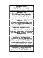

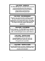
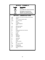


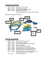
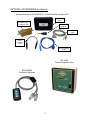
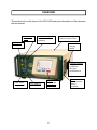
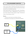
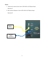
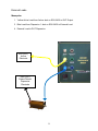
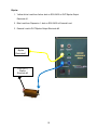
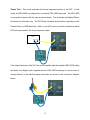
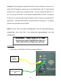
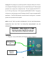
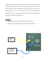
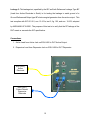
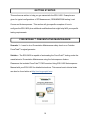
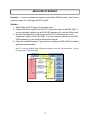

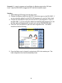
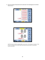
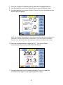
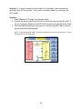
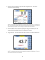
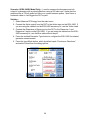
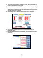
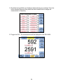
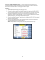
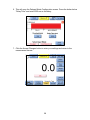
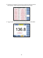
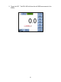
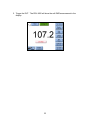
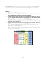
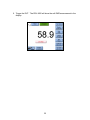
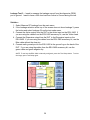
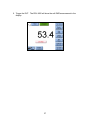
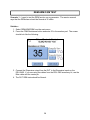
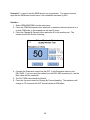
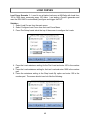

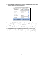
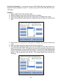
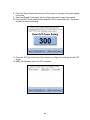
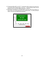
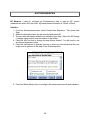
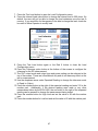
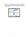
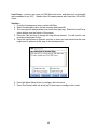
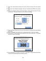
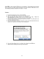
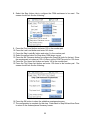
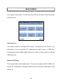
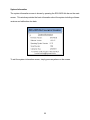
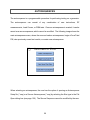
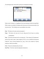
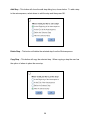
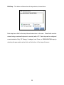
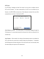
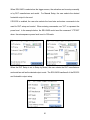
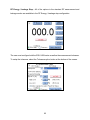
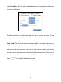
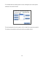
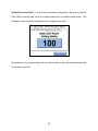
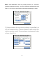

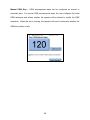
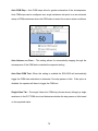
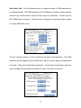
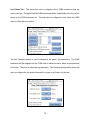
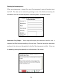
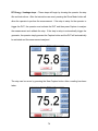
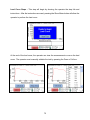
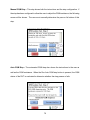
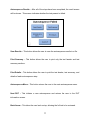
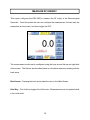
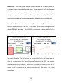
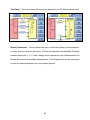
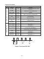
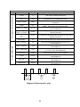
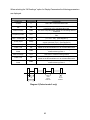
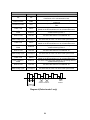
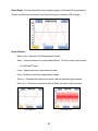
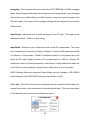
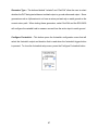


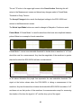

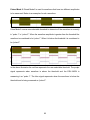
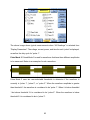
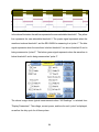
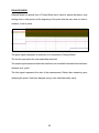
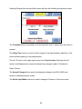
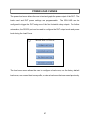
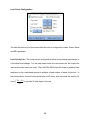
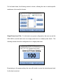
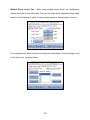
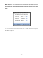
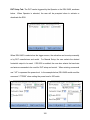
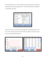
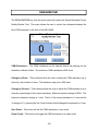


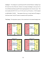
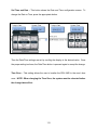
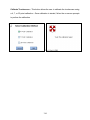
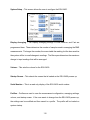
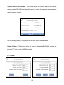
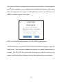
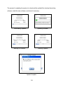
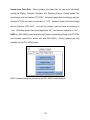
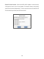
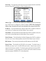

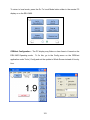
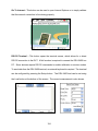
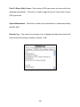
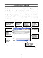
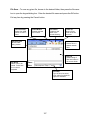
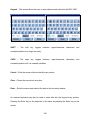
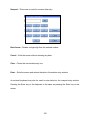
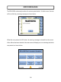
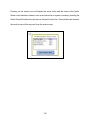
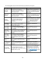

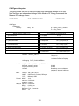
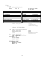
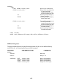
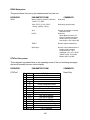
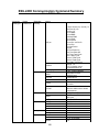

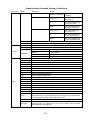
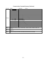
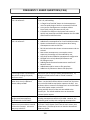

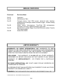

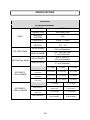
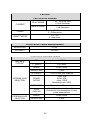
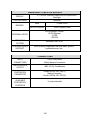
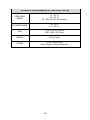
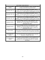


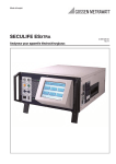


![FV2300-LNX/M1 - FAST CORPORATION[株式会社ファースト]](http://vs1.manualzilla.com/store/data/006632357_2-50af94545191910a20993314a5b81ad3-150x150.png)