1
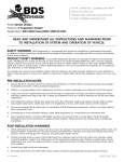
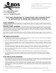
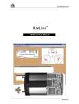
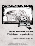
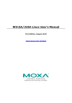
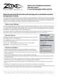
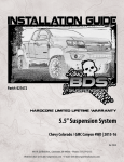
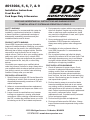
#013004, 5, 6, 7, & 9
Installation Instructions
Front Box Kit
Ford Super Duty & Excursion
Read and understand all instructions and warnings prior
to installation of system and operation of vehicle.
SAFETY WARNING
BDS Suspension Co. recommends this system be
installed by a professional technician. In addition
to these instructions, professional knowledge of
disassembly/ reassembly procedures and post
installation checks must be known.
PRODUCT SAFETY WARNING
Certain BDS Suspension products are intended to
improve off-road performance. Modifying your vehicle
for off-road use may result in the vehicle handling
differently than a factory equipped vehicle. Extreme
care must be used to prevent loss of control or
vehicle rollover. Failure to drive your modified vehicle
safely may result in serious injury or death. BDS
Suspension Co. does not recommend the combined
use of suspension lifts, body lifts, or other lifting
devices.
You should never operate your modified vehicle
under the influence of alcohol or drugs. Always drive
your modified vehicle at reduced speeds to ensure
your ability to control your vehicle under all driving
conditions. Always wear your seat belt.
Pre-Installation Notes
1. Special literature required: OE Service Manual for
model/year of vehicle. Refer to manual for proper
disassembly/reassembly procedures of OE and
related components.
2. Adhere to recommendations when replacement
fasteners, retainers and keepers are called out in
the OE manual.
3. Larger rim and tire combinations may increase
leverage on suspension, steering, and related
components. When selecting combinations larger
than OE, consider the additional stress you could
be inducing on the OE and related components.
4. Post suspension system vehicles may experience
drive line vibrations. Angles may require tuning,
slider on shaft may require replacement, shafts
may need to be lengthened or trued, and U-joints
may need to be replaced.
5. Secure and properly block vehicle prior to
installation of BDS Suspension components.
Always wear safety glasses when using power
tools.
6. If installation is to be performed without a
hoist, BDS Suspension Co. recommends rear
alterations first.
7. Due to payload options and initial ride height
variances, the amount of lift is a base figure. Final
ride height dimensions may vary in accordance
to original vehicle attitude. Always measure the
attitude prior to beginning installation.
POST-INSTALLATION WARNINGS
1. Check all fasteners for proper torque. Check
to ensure for adequate clearance between all
rotating, mobile, fixed, and heated members.
Verify clearance between exhaust and brake
lines, fuel lines, fuel tank, floor boards and wiring
harness. Check steering gear for clearance. Test
and inspect brake system.
2. Perform steering sweep to ensure front brake
hoses have adequate slack and do not contact
any rotating, mobile or heated members. Inspect
rear brake hoses at full extension for adequate
slack. Failure to perform hose check/ replacement
may result in component failure. Longer
replacement hoses, if needed can be purchased
from a local parts supplier.
3. Perform head light check and adjustment.
4. Re-torque all fasteners after 500 miles. Always
inspect fasteners and components during routine
servicing.
102 S. Michigan Avenue • Coldwater, MI 49036
517-279-2135 • www.bds-suspension.com
rev. 4/26/2007
Page of 4
PARTS LIST FOR #013004,
013005, 013006
Part#
Qty Description
963181012Q4
963181100H4
N96FH
W96S
083401R
8
8
1
083403R 1
01067-11
01057-11
BP1234011
4031
01019
2
01027-1 2
01067-11
01057-11
M02016RB 4
65-1
4
9/16 x 3-1/8 x 10-1/2" Square U-bolt
(013004, 013005 only)
or
9/16 x 3-1/8 x 11" Radius U-bolt (013006
only)
9/16" High Nut
9/16" SAE Flat Washers
Pitman Arm (013004 only)
or
Pitman Arm (013005, 013006 only)
Track Bracket (013004 only)
or
Track Bracket (013005, 013006 only)
Bolt Pack
Bolt Pack
4" Link Kit
Bump Stop Drop
Track Bracket (013004 only)
or
Track Bracket (013005, 013006 only)
Large Shock Eye
3/4 x .134" x 1.650" Dom Sleeve
FIG. 1
4. Remove the anti-sway bar end links (Fig 2). Remove
the cotter pin and castle nut from the drag link at the
pitman arm. Use a tie rod puller to separate the tie rod
end from the pitman arm.
PARTS LIST FOR #013007 & 013009
Part#
Qty Description
583581500R4
583581200R4
N58FH
8
W58S
8
B381G21
SBLA
1
B382G51
LW38
2
45313-11
4KB-W96 2
5/8 x 3-5/8 x 15" Round U-bolt (013007)
or
5/8 x 3-5/8 x 12" Round U-bolt (013009)
5/8" High Nut
5/8" SAE Flat Washers
3/8 x 1" Bolt
Brake Adapters
3/8 x 2" Bolt
3/8" Lock Washer
5/8 x .109 x 1.375" Sleeve
4" Lift Block (013007 only)
FIG. 2
5. Remove the three bolts that retain the factory track
bar bracket to the frame. Set the bracket off to the
side and retain the factory fasteners for later use.
(Fig 3)
Installation INSTRUCTIONS
Helpful Hint: The following installation may go easier if
you remove the front bumper before you begin. The bumper is attached by four bolts. The removal will require two
people. This is not necessary for installation, but will make
removal of the front spring eye bolts easier.
1. Unhook the track bar at the top end where it attaches
to the frame bracket. Retain fasteners for later use.
2. Raise the front of the vehicle and support with jack
stands. Be sure to chock the rear tires. Remove the
wheel and OE shock.
3. With a large set of pliers, bend the OE brake line
mounting tab on the frame out to 45 degrees. Remove
the bracket from the frame and retain the OE fastener.
(Fig 1)
Page of 4
FIG. 3
6. Remove the nut and washer from the steering shaft
that retain the pitman arm. Remove the pitman arm
using a pitman arm puller.
Complete the following instructions one side at a time.
7. Place a hydraulic jack under the front axle. Remove
the u-bolts that hold the leaf spring to the axle. Slowly
lower the jack allowing the axle to separate from the
leaf spring. CAUTION: Be sure not to over extend the
brake lines or vent tube.
8. Remove the shackle and solid mount spring eye bolts.
Note: These bolts are coated with loctite from the
factory. You will need to remove the radiator condenser mounts one side at a time in order to remove
the front spring eye bolts. Loosen the shackle to frame
bolt. Do not remove, just loosen.
9. Remove the stock leaf spring and repeat for the opposite side.
10. Install the supplied drop pitman arm to the steering
shaft and retain with the factory fasteners. Torque to
200 ft/lbs.
11. Install the supplied track bar bracket in the factory location. Attach using the three OE fasteners and torque
to 130 ft/lbs (Fig 4).
FIG. 4
12. Remove the factory bump stops from the frame. Install
the bump stop drop brackets between the OE bump
stops and the frame. Use the supplied
3/8” bolts, nuts and washers to retain the drop bracket
to the frame and use the OE fasteners to attach the
bump stop to the drop bracket. Torque to 30 ft/lbs
(Fig 5)
FIG. 4
13. Lower the front axle using the hydraulic jack to aid in
leaf spring installation. CAUTION: Be sure not to over
extend the brake line or vent tube.
14. Install the supplied front leaf springs #003602 (6”), or
#003802 (8”). The double wrapped eye goes toward
the front. Install the factory spring eye bolts in to the
springs and install nuts, but do not tighten at this time.
15. Raise the front axle with the jack. Align the leaf spring
center pins in the holes in the axle spring pads. Raise
the axle until the springs are seated flat on the spring
pads. Install the supplied front u-bolts over the springs
and through the stock original u-bolt plates. Retain
the u-bolts using the supplied high nuts and washers.
Tighten bolts but do not torque at this time.
16. With the front axle at full droop, move the brake line
mounting bracket. The bracket should rest about 2”
down from it’s original position and about 3” forward.
Reroute brake line as needed. Use the bracket as a
template and drill a new hole in the frame. Attach the
bracket to the frame using the OE fastener that you
remove earlier.
17. Attach the drag link to the pitman arm and retain using
the factory nut. Torque to 60 ft/lbs, and then tighten
until the cotter pin hole line up. DO NOT LOOSEN
THE NUT TO LINE UP THE COTTER PIN. Install a
new cotter pin.
18. Install the front BDS shocks at this time. If you are
installing a dual shock system, do so at this time.
19. Install the front tire/wheel assembly and tighten to OE
specification. Torque specifications can be found in
the owner’s manual.
20. Raise the vehicle to remove the jack stands and lower
the vehicle on to the ground. CAUTION: When lowering the vehicle be sure to watch the hanging track bar
so that it doesn’t contact anything.
21. With the weight of the vehicle on the wheels. Tighten
the u-bolts to 100-120 ft/lbs. Raise the front track bar
to align it with the new drop bracket. If the track bar
doesn’t line up with the bracket, just turn the steering
wheel. This will shift the axle and make the track bar
line up easily. If installing the 6” kit attach the track
bar in the upper hole on the drop bracket. If install the
8” kit attach the track bar to the lower hole. If installing box kit #013004, attach the track bar using the
supplied 9/16” grade 10 bolt, nut and washers. Insert
the bolt from the back side forward. If installing kit
#013005, or #013006, then use the OE bolt to retain
the track bar to the drop bracket. Torque OE bolt to
369 ft.lbs. or 9/16" bolt to 130 ft.lbs.
22. Bounce the front of the vehicle to allow the shackles
to swing out to their intended position. Torque front
spring hanger bolt to 203 ft.lbs. Spring to shackle and
shackle to frame bolts to 185 ft.lbs.
23. Grease the supplied sway bar bushings and install
them in to the supplied anti-sway bar links. Grease the
supplied sleeves and install them in to the bushings.
Install the sway bar links in place of the OE links. Use
the two 12mm bolts, nuts, and washer supplied to attach the links to the frame mount. Use the OE fasteners to attach the links to sway bar. Torque all sway
bar bolts to 35 ft/lbs. Note: On '99 & up models, it will
be necessary to remove the OE bracket on top of the
frame rail that originally held the top end of the sway
bar links. Flip the OE bracket over and attach it to the
bottom of the frame and retain using OE fasteners.
Torque to 55 ft/lbs.
Page of 4
24. Check all fasteners for torque. Adjust the drag link to
center the steering wheel.
CAUTION: You will want to test the front driveshaft rotation at full droop. You will need to clearance grind the drive
shaft for smooth rotation. You may need to lengthen the
front drive shaft. Be sure to test this at full droop before
driving the vehicle.
Be sure to tighten all fasteners after 100 miles. Be sure to
tighten the spring U-bolts again after 500 miles.
REAR INSTALLATION #013007 & #013009
1. Raise the rear of the vehicle and install jack stands
under the frame. Be sure to chock the front wheels.
Remove the rear tires and wheels.
2. Remove the OE shocks.
3. Use a large set of pliers to bend the OE brake line
bracket out flat where it attaches to the frame. Be
sure not to kink the brake line. Drill out the OE rivet
that attaches the bracket to the frame. With the rivet
removed, move the bracket below the frame and allow
it to hang loose. It will be reattached later after the
springs are installed.
4. Remove the factory brake line bracket from the top of
the pinion on the axle. Retain OE fasteners.
5. Complete this step one side at a time. Place a jack
under the axle and remove the factory u-bolts. Remove the spring eye bolts and remove the factory
spring. Loosen, but do not remove, the shackle to
frame bolt.
6. Use the jack to lower the axle to allow for installation of replacement springs. CAUTION: Be sure not
to over extend the brake lines or vent tube. Reroute
brake line as necessary. Install new BDS spring
#003609 (6”), or #003809 (8/10”). Install factory spring
eye bolts and nuts, but do not tighten at this time.
7. Raise the axle with the jack. Be sure to align the leaf
spring center pin with the hole in the spring mounting
plate. Raise the axle until the spring sets flush on the
plate. Install the supplied u-bolts and factory u-bolt
plate and retain using supplied high nuts and washers. Tighten u-bolts to 60 ft/lbs using an “X” pattern.
8. Install wheels and tires. Tighten lug nuts to OE specification.
9. Raise the vehicle to remove jack stand and lower the
vehicle on to the ground. Bounce the vehicle to allow
the shackles to swing out to their intended position.
Torque the spring to frame bolts, shackle to spring,
and shackle to frame bolts to 185 ft.lbs.
Page of 4
10. Tighten the u-bolts to 130-150 ft/lbs using an “X” pattern.
11. Loosen the u-bolt that holds the lower shock mount in
place. Rotate the lower shock mount upwards in order
to install supplied BDS shocks at this time. Tighten
the lower shock mount u-bolt to 35 ft.lbs.
12. Install flat brake line relocation bracket to the top of
the pinion using the OE fastener and tighten. Attach
the OE brake line bracket to the supplied bracket with
the supplied 3/8 x 1” bolt, nut and washer.
13. Install the supplied sleeve between the OE brake line
bracket and the frame rail using the supplied
3/8 x 2” bolt, nut and washer. Tighten to 25 ft/lbs.
If the vehicle is equipped with a carrier bearing, install
BDS carrier bearing lowering kit at this time.
Recheck all fasteners for torque. Re-torque all fasteners
after 100 miles. Be sure to re-torque the U-bolts after
100 miles and after 500 miles.
If rear drive line vibration occurs, you must adjust the
carrier bearing spacer as well as the rear pinion angle
using a degree wedge (sold separately). This fine tuning
of the drive line angle will vary from vehicle to vehicle.