1
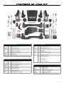
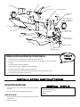
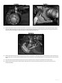
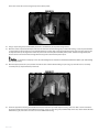
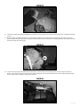
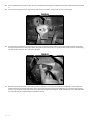
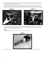
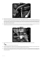
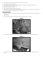
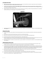
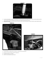
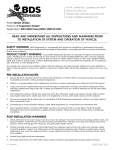
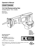
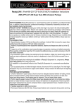
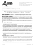
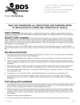
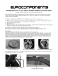
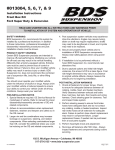
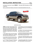
Part#: 021633
7” High Clearance Suspension System
Chevy/GMC 2500 & 3500 HD 4WD | 2001-2010
Rev. 021014
491 W. Garfield Ave., Coldwater, MI 49036 . Phone: 517-279-2135
Web/live chat: www.bds-suspension.com . E-mail: [email protected]
Read And Understand All Instructions
And Warnings Prior To Installation Of
System And Operation Of Vehicle.
Your truck is about to be fitted with the best suspension system on the market today. That means you will be driving the
baddest looking truck in the neighborhood, and you’ll have the warranty to ensure that it stays that way for years to come.
Thank you for choosing BDS Suspension!
BEFORE YOU START
BDS Suspension Co. recommends this system be installed by a professional
technician. In addition to these instructions, professional knowledge of
disassembly/ reassembly procedures and post installation checks must be
known.
FOR YOUR SAFETY
Certain BDS Suspension products are intended to improve off-road performance. Modifying your vehicle for off-road use may result in the vehicle
handling differently than a factory equipped vehicle. Extreme care must
be used to prevent loss of control or vehicle rollover. Failure to drive your
modified vehicle safely may result in serious injury or death. BDS Suspension
Co. does not recommend the combined use of suspension lifts, body lifts, or
other lifting devices. You should never operate your modified vehicle under
the influence of alcohol or drugs. Always drive your modified vehicle at reduced speeds to ensure your ability to control your vehicle under all driving
conditions. Always wear your seat belt.
BEFORE INSTALLATION
Special literature required: OE Service Manual for model/year of vehicle.
Refer to manual for proper disassembly/reassembly procedures of OE and
related components.
Adhere to recommendations when replacement fasteners, retainers and
keepers are called out in the OE manual.
Larger rim and tire combinations may increase leverage on suspension,
steering, and related components. When selecting combinations larger
than OE, consider the additional stress you could be inducing on the OE and
related components.
Post suspension system vehicles may experience drive line vibrations.
Angles may require tuning, slider on shaft may require replacement, shafts
may need to be lengthened or trued, and U-joints may need to be replaced.
Secure and properly block vehicle prior to installation of BDS Suspension
components. Always wear safety glasses when using power tools.
If installation is to be performed without a hoist, BDS Suspension Co. recommends rear alterations first.
Due to payload options and initial ride height variances, the amount of lift
is a base figure. Final ride height dimensions may vary in accordance to
original vehicle attitude. Always measure the attitude prior to beginning
installation.
2 | 021663
FITMENT GUIDE
7”Lift 2001-07 Classic Body Style
35x12.50 on 16x8 with 4.5” backspacing
37x12.50 on17/18x9 with 5” backspacing - narrow track
37x12.50 on17/18x9 with 5.5” backspacing - standard
37x12.50 on 20x9 with 5.75” backspacing
7”Lift 2007-10 New Body Style
35x12.50 on17/18x9 with 5” backspacing - narrow track
35x12.50 on17/18x9 with 5.5” backspacing - standard
35x12.50 on 20x9 with 5.75” backspacing
BEFORE YOU DRIVE
Check all fasteners for proper torque. Check to ensure for adequate clearance
between all rotating, mobile, fixed, and heated members. Verify clearance
between exhaust and brake lines, fuel lines, fuel tank, floor boards and wiring
harness. Check steering gear for clearance. Test and inspect brake system.
Perform steering sweep to ensure front brake hoses have adequate slack and
do not contact any rotating, mobile or heated members. Inspect rear brake
hoses at full extension for adequate slack. Failure to perform hose check/
replacement may result in component failure. Longer replacement hoses, if
needed can be purchased from a local parts supplier.
Perform head light check and adjustment.
Re-torque all fasteners after 500 miles. Always inspect fasteners and components during routine servicing.
021632 Standard Track Width
021635 Narrow Track Width
Part #
Qty
Description
Part #
Qty
01178
1
Steering Knuckle - DS
02150
1
Steering Knuckle - PS
01179
1
Steering Knuckle - PS
02151
1
Steering Knuckle - DS
568
Description
1
Bolt Pack - CV Spacer
02329
2
CV Spacer
12
10mm-1.5 x 70mm SHCS
02330
2
GM HD Brakeline Bracket
02328
2
CV Spacer
02332
2
Steering Stop
578
021633 Box Kit
Part #
Qty
Description
1
Bolt Pack - CV Spacer
12
10mm-1.50 x 50mm bolt
12
10mm washer
2
14mm flat washer
2
14mm-1.50 x 90mm bolt
02197B
1
Torsion Bar Relocation - DS
02198B
1
Torsion Bar Relocation - PS
02190B
1
Front Crossmember
011517
02191B
1
Rear Crossmember
Part #
Qty
02193B
1
Differential Tube - PS
BB088
2
5in Flat Block
02437
1
D/S Boot Extension
962961500QB
4
9/16 x 2-916 x 15 Square
D/S Boot Extension O-rings
W96S-B
8
9/16 SAE Flat Washer
N96FH-B
8
9/16 Fine High Nut
B381
2
Description
021663 | 3
021634
021634
Part #
Qty
02196
2
Description
2
3/8"-16 nylock nut
Torsion Bar Bracket Spacer
2
7/16"-14 nylock nut
9/16"-12 x 2-3/4" bolt
15
1
.750 x .090 x 2.950 Sleeve
2
01187
1
Weld-In Plate
4
9/16" SAE washer
9/16"-12 prevailing torque nut
911109
2
Sway Bar Link
2
SB35BK
2
Hourglass Bushing
2
5/8"-11 x 1-3/4" bolt
SB26BK
4
Shock Stem Bushing
4
5/8" SAE washer
2
5/8"-11 nylock nut
54587
2
.750 x .090 x 1.575 Sleeve
342701
1
Loctite - 1ml
099000
6
11.5in Nylon Cable Tie
01196B
2
GM HD Rear Bump Stop
S10076
4
7/16 Stem Washer
02102B
2
Offset Sway Bar Bracket
M02096-BK
2
Pyramid Bushing
02192B
1
Differential Drop Bracket - PS
02194B
1
Differential Skid Plate
02199B
2
Bump Stop
01185B
1
Drop Bracket
02380B
1
Front Skid Plate
3624BK
2
Bushing - Differential Bracket
422
1
539
569
4 | 021663
571
1
Bolt Pack - Torsion Bar Brackets
2
3/4"-10 x 4-1/2" bolt
4
3/4" SAE washer
2
3/4"-10 nylock nut
2
9/16"-12 x 3-1/2" bolt
4
9/16" SAE washer
2
9/16"-12 Prevailing torque nut
3
1/2"-13 x 1-1/4" button head bolt
3
1/2"-13 x 1-1/2" button head bolt
6
1/2" x 1 1/4" Stainless Flat Washer
1
Bolt Pack - Bump Stops/Misc.
12
3/8"-16 x 1-1/4" bolt
18
3/8" SAE washer
Bolt Pack - Rear Bump Stop
6
3/8"-16 Prevailing torque nut
4
3/8"-16 x 1-1/4" bolt
4
3/8"-16 serrated flanged nut
4
3/8"-16 prevailing torque nut
6
1/4”-20 x 3/4” bolt
8
3/8" USS flat washer
6
1/4" split lock washer
1
Bolt Pack - Main
12
1/4" SAE Washer
2
5/8"-11 x 6" bolt
6
1/4"-20 nylock nut
2
5/8"-11 x 5" bolt
6
Wire Clamps
4
5/8"-11 prevailing torque nut
8
5/8" SAE flat washer
1
9/16"-12 x 4-1/2" bolt
3
9/16"-12 prevailing torque nut
6
9/16" SAE flat washer
2
9/16"-12 x 1-1/2" bolt
5
10mm-1.50 x 60mm bolt
5
10mm flat washer
2
3/8”-16 standard hex nut
2
3/8” SAE flat washer
2
3/8" lock washer
1
Bolt Pack - Sway Bar Links
572
15
02192
01185
02199
117300007 (QTY 4)
3624 (QTY 2)
02199
M02096-RB
(QTY 2)
02191
CV SPACER (QTY 2)
02329 - NARROW or
02328 - TRADITIONAL
SB26BK (QTY 4)
02190
02319
02197 - DRV
02198 - PASS
911109 (QTY 2)
02193
LOWER A-ARM
NOT INCLUDED
02196 (QTY 2)
(ALUM SPACER)
02194
02102 (QTY 2)
54587 (QTY 2)
SB35BK (QTY 2)
tROUBLESHOOTING INFORMATION FOR YOUR VEHICLE
1.
20” wheels with 5-5-3/4” backspacing recommend to reduce trimming.
2.
Traction bars will not fit standard cab short box models and are designed to work on vehicles with
4-8” of lift.
3.
Gas models require exhaust modification.
4.
Requires frame bracket and differential mount modification.
5.
Narrow track knuckle will slightly increase turning radius.
6.
For tail high stance use 119157 add-a-leaf with the block kit or 069207 with leaf spring kit.
7.
Dually applications will require custom u-bolts.
INSTALLATION INSTRUCTIONS
1.
Park the vehicle on a flat, clean surface and block the rear wheels
for safety.
Torsion Bar Unloading Tool
2.
Disconnect the positive and negative battery cables.
ReciprocatingSaw
Front Installation
1.
Raise the front of the vehicle and support with jack stands under
the frame rails.
2.
Remove the wheels.
Welder
021663 | 5
3.
Measure and record the length of the exposed thread on the torsion bar adjuster bolts (Fig 1). Record the lengths here for use later during
the installation
DRV Side:_________ PASS Side:__________
FIGURE 1
4.
Unload the torsion bars but do not remove. Save adjuster bolt/retainer block.
5.
Mark the unloaded torsion bars to indicate DRV side and PASS side. Also mark the bars to indicate front versus rear.
6.
Remove the torsion bar adjuster plate by pushing the torsion bar forward to allow the plate to drop free. On most vehicles this will require
a using a hammer/punch or air hammer. Access the end of the torsion bar through the hole in the back of the torsion bar crossmember
and drive forward. Leave the torsion bars in the lower control arms.
Torsion bars are under extreme pressure. A proper torsion bar tool is necessary to unload the bars. A tool designed specifically for GM
torsion bars (#J36202 or equivalent) is required. Most auto parts store will lend these tools for little or no charge.
7.
Remove the two bolts that attach the torsion bar crossmember to the frame rails (Fig 2). Remove the torsion bar crossmember from the
vehicle. Save bolts and crossmember.
Figure 2
6 | 021663
8.
Remove the torsion bars by pulling them rearward out of the lower control arms. Set the torsion bars aside.
9.
Remove the front plastic splash guard, save splash guard bolts. If equipped, remove the four bolts mounting the factory belly pan to the
frame (Fig 3) These will not be reused.
FIGURE 3
10. Disconnect the sway bar end links from the sway bar and the lower control arms (Fig 4). Discard the link assemblies.
11. Disconnect the tie rod ends from the steering knuckles. Remove the tie rod end nuts and save. Strike the knuckle near the tie rod end to
dislodge the tie rod end taper (Fig 4). Remove the tie rod ends from the knuckles.
Figure 4
12. Disconnect the ABS brake wire from the connector at the top of the frame (Fig 5) Remove the wire from the plastic retainers on the frame
and upper control arm (Fig 6).
13. Disconnect the rubber brake line brackets from the upper control arm and the steering knuckle (Fig 6). Save hardware.
021663 | 7
FigURE 5
FigURE 6
14. Remove the two bolts mounting the brake caliper assembly to the steering knuckle and hang the caliper out of the way (Fig 7). Do not
hang the caliper by the brake hose. Save mounting bolts.
Figure 7
15. If equipped, remove the rotor retaining clips from the wheels studs. These will not be reused. Remove the brake rotor and set aside.
16. Carefully remove the hub dust cover. Save cover (Fig 8).
17. Remove the CV axle nut and washer. Save hardware.
18. Remove the CV axle flange bolts at the differential (Fig 9). There are 6 bolts per side. Discard the bolts.
8 | 021663
FigURE 8
FigURE 9
19. Remove the upper ball joint nut. Thread the nut back on by hand one or two turns. Strike the knuckle near the upper ball joint to release
the taper. Remove the upper ball joint nut (save) and remove the ball joint from the knuckle. Allow the knuckle to swing out and remove
the CV axle from the hub (Fig 10). Mark the CV axle to indicate DRV side and PASS side.
FIgure 10
20. Remove the lower ball joint nut and thread back on by hand one or two turns. Strike the knuckle near the ball joint to release the taper. Remove the ball joint nut and remove the knuckle from the lower control arm. Save the lower ball joint nut and set the knuckle/hub assembly
aside.
21. Disconnect the shocks from the frame and lower control arm. Remove shocks. The shocks and hardware will not be reused.
22. Remove the front and rear lower control arm bolts and remove the control arms from the vehicle (FIg 11) Save the control arms and
mounting hardware.
021663 | 9
Figure 11
23. Remove the factory bump stops from the frame (Fig 12). Save bump stops and hardware.
24. Make an alignment mark on the front driveshaft and front differential input yoke. Remove the four bolts/clamps from the yoke and remove
the front driveshaft from the differential (Fig 13). Slide the driveshaft out of the transfer case. Save the driveshaft hardware.
25. Remove the four bolts mounting the rear crossmember to the rear lower control arm pockets (Fig 14). Remove the crossmember from the
vehicle. The crossmember and hardware will not be reused.
FigURE 12
FigURE 13
10 | 021663
Figure 14
26. Disconnect the electrical connector from the front differential actuator (Fig 11) Remove the wire from the three plastic wire retainers along
the top of the differential.
27. Disconnect the axle breather tube from the driver’s side of the differential.
28. Loosen but do not remove all of the front differential mounting bolts. There are two on the passenger’s side, one on the upper front driver’s
side and one on the lower rear driver’s side.
29. Locate the remaining wing of the rear crossmember on the lower rear driver’s side control arm pocket. This portion of the frame must be
removed to clear the front differential in its new, lower position. A precise measurement and cut is outlined later in the instructions but to
make removing the differential easier the wing portion can be cut off now. Using a reciprocating saw (recommended), hack saw or cut-off
wheel, remove the wing just inside of the control arm pocket (Fig 15). Take care not to cut into the differential housing or bolt.
Do not use any type of flame cutting as the vehicle undercoating is flammable.
Figure 15
30. Support the front differential with an appropriate jack. Remove the differential mounting hardware and lower the differential from the
vehicle and set aside. Save hardware.
31. The lower rear driver’s side control arm pocket must be trimmed to provide clearance for the front differential. Measure inward from the
lower control arm mounting hole 1-3/4” and mark on both the front and back surfaces of the pocket (Fig 16). Make vertical cut lines at the
021663 | 11
marks and connect the cut lines along the top surface of the pocket.
Figure 16
1-3/4
32. Using a reciprocating saw (recommended), hack saw or cut-off wheel, cut the pocket along cut lines.
33. With the control arm pocket trimmed, be sure the area around the cut is free from grease, oil and undercoating. Locate the provided weldin support plate (01187) and place it up to the frame where the cut was made. The angled edge of the plate goes to the top. Align the top
of the plate to the top cut edge of the control arm pocket and center the plate horizontally in the pocket. The bottom edge of the plate
must be at least 1/4” above the bottom edge of the factory pocket. Tack weld the plate in place.
It is important to completely remove the undercoating from the weld area to avoid weld contamination and keep the undercoating
from igniting/melting.
34. With the support plate tack in place, double check the location and then finish welding it in place (Fig 17). Allow the area to cool slowly
and then paint any exposed metal to prevent rust.
Figure 17
35. The front upper mount bushing of the differential must be removed to provided adequate steering clearance. Mark a cut line around the
mount that is flush with the top of the differential housing. Using a reciprocating saw (recommended) or hack saw, cut the mount off of the
differential (Fig 18). Take extra care not to cut into the differential housing.
12 | 021663
Figure 18
36. Install the provided large bushings (3624RB) and 0.750” OD x 2.950” long sleeve (15) into the eye of the new driver’s side differential bracket
(01185).
37. Place the driver’s side differential bracket up to the front of the differential to indicate the four housing bolts that need to be removed.
Remove the four bolts, place the bracket in position and fasten with new 10mm x 60mm bolt and washers (BP 539). Use Loctite on the bolt
threads and torque to 30 ft-lbs (Fig 19).
Figure 19
38. Locate the new passenger’s side differential bracket (02192). Install the bracket on the existing studs on the passenger’s side factory
bracket. Fasten with the original nuts and washers. When installed the open side of the bracket will face inward and the bracket will taper
down as it goes to the rear (Fig 20). Torque nuts to 65 ft-lbs.
Figure 20
021663 | 13
39. Inspect the inside factory control arm mounting holes. There will be a sharp lip left from the original control arm/hardware. Use a file or
rotary grinder to remove the sharp lip left from the control arms (Fig 21). This will allow the new cross members to be installed easily.
Figure 21
40. Locate the new front crossmember (02190). Install the crossmember in the front lower control arm pockets so that the two longer differential mounting tabs are on the driver’s side pointing rearward (Fig 22). Fasten the crossmember with the original lower control arm
hardware. Run the bolts from front to rear. Leave hardware loose.
Figure 22
41. Using an appropriate jack, raise the differential up into the vehicle. Align the new driver’s side differential bracket in the front crossmember
mounting tabs. Align the passenger’s side mounting holes to the new bracket (Fig 23). Fasten the driver’s side mount with a 9/16” x 4-1/2”
bolt, nut and 9/16” SAE washers. Fasten the passenger’s side with 9/16” x 1-1/2” bolts, nuts and 9/16” SAE washers (BP 539). Leave the
driver’s side bolt loose. Tighten the passenger’s side bolts just enough to make the two mounting surfaces set flush.
14 | 021663
Figure 23
42. Install the new provided bump stops (M02096RB) on the new rear crossmember (02191) with 3/8” hex nuts, flat and lock washers (BP 539).
Tighten hardware securely (Fig 24).
Figure 24
43. Install the rear crossmember in the rear lower control arm pockets so that the differential mount lines up with the differential (Fig 25) Fasten the crossmember with the original lower control arm hardware. Run the bolts from front to rear. Leave hardware loose.
Figure 25
021663 | 15
44. Fasten the differential to the new mount in the rear crossmember with the original rear differential bolt/nut. Run the bolt from the outside
in.
45. Locate the two existing holes in the original bump stop mounts on the frame. Drill the small hole out to 7/16” (Fig 26).
Figure 26
46. Locate the new provided bump stop brackets (02199). Place a bump stop bracket up to the original mount and line up the center of the
two slots with the two holes in the factory mount. Using the third slot in the bracket as a guide, mark the center position to be drilled (Fig
27). Remove the bracket and drill a 7/16” hole at the mark.
Figure 27
47. With the holes drilled, attach the new brackets to the frame with 3/8” x 1-1/4” bolts, nuts and 3/8” washers (BP 572). The two outer bolts
should be all the way to the outer edge of the slots in the brackets (bracket push inward toward frame as far as possible). Torque bolts to
30 ft-lbs. Install the factory bump stop on the new brackets with the original mounting nut. Install the bump stop so it is offset toward the
rear of the vehicle (Fig 28). Tighten bump stop hardware securely.
16 | 021663
Figure 28
48. Install the factory lower control arms into the new crossmembers. Fasten the control arms with 5/8” x 5” bolts (front), 5/8” x 6” bolts (rear),
nuts and 5/8” SAE washers (BP 539). Run the bolts from the front to rear (Fig 29). Leave hardware loose.
Figure 29
49. Go back and torque the four differential bolts to 90 ft-lbs. Torque the factory control arm pocket bolts to 125 ft-lbs. DO NOT tighten the
new control arm bolts at this time. This will be done at the end of the installation.
50. Locate the new differential skid plate (02194). Position the skid plate so that it aligns to holes with the welded nuts on the bottom driver’s
side of the rear crossmember (Fig 30). Fasten the skid plate with 1/2” x 1-1/4” button head bolts and stainless steel washers (BP 571). Snug
hardware so the front of the skid plate sets up near the bottom of the front crossmember.
51. Locate the new crossmember support tube (02193). The tube is formed to clear the differential when installed. Position the support tube
so it set properly against the bottom of the front and rear crossmembers and aligned to the mounting holes. Fasten the tube to the rear
crossmember with a 1/2” x 1-1/4” button head bolt and stainless steel washer (BP 571). Again, snug hardware so the tube sets up near the
bottom of the front crossmember (Fig 30).
021663 | 17
Figure 30
52. Locate the new front “BDS” skid plate/splash guard (02319). Loosely attach the skid plate to the original splash guard mounting holes on
the upper frame crossmember using the original splash guard bolts. Position the skid plate up to the bottom of the front crossmember
“sandwiching” the support tube and differential skid plate. Fasten the front skid plate, differential skid plate and support tube to the front
crossmember with 1/2” x 1-1/2” button head bolts and stainless steel washers (BP 571) in the welded nuts in the crossmember (Fig 31). Apply Loctite to the bolt threads and torque to 55 ft-lbs.
Figure 31
53. With the front hardware tight, remove the rear button head bolts one at a time and apply Loctite to the threads. Reinstall and torque to 55
ft-lbs. Torque the front factory splash guard bolts to 25 ft-lbs.
54. Located the factory shock mount bolted to the lower control arm. Remove the shock mount by removing the two mounting bolts. These
bolts are held in place with thread locker so take care not to break the bolts with excessive force when removing. Save the bolts and discard the bracket.
55. Install the provided aluminum spacer (02196) into the torsion bar hex hole in the control arm (Fig 32). Install the new torsion bar bracket
on the control arm so that the large mounting holes align with the aluminum spacer and the smaller slots align with the original shock
mount bolt holes (Fig 33). Loosely fasten the bracket with the provided ¾” x 4-1/2” bolt, nut and ¾” SAE washers.
56. Fasten the torsion bar bracket to the original shock mount holes with the original mounting bolts. Use Loctite on the bolt threads and
torque to 30 ft-lbs. With the shock mount hardware tight, torque the ¾” bolt to 150-165 ft-lbs.
18 | 021663
FigURE 32
FigURE 33
57. Remove the hub bearing and brake dust shield from the factory steering knuckles (Fig 34). Be sure to note which hub goes on which side
of the vehicle. Locate the hub o-ring inside the knuckle hub bore. Using a small flat head screw driver remove the o-ring for use in the new
knuckle (Fig 35). Save mounting bolts, o-ring, dust shield and hub, discard the knuckle.
FigURE 34
FigURE 35
58. Locate the new steering knuckles and identify the driver’s and passenger’s side. Install the appropriate knuckle on the lower control arm
and fasten with the original lower ball joint nut. Swing the knuckle up and attach to the upper ball joint with the original nut. Narrow Track
Knuckles: Install the provided “L” shaped brake line bracket (02330) to knuckle with the upper ball joint nut. Position the bracket so the long tab is
toward the rear of the vehicle (Fig 41A). Torque the upper ball joint nut to 37 ft-lbs and the lower ball joint nut to 74 ft-lbs (Fig 36).
59. Standard Knuckle Kits Only: Install the factory hub o-ring into the new knuckle hub bore. Install the hub on the appropriate new knuckle so
that the ABS line runs out under the steering arm (front - Fig 36A). Fasten the hub with the factory bolts. Apply Loctite to the bolt threads
and torque to 133 ft-lbs.
The original brake dust shield will not be used.
60. Narrow Track Knuckle Kits Only: Install the factory hub o-ring into the new knuckle hub bore. Install original hub with the original brake
dust shield on the appropriate new knuckle so that the ABS line runs out the top of the hub. Fasten the hub to the knuckle with three of
the four original bolts and one of the provided 14mm x 100mm bolts/washers (BP 578). Apply Loctite to the bolt threads and torque to 133
ft-lbs. (Fig 36B)
021663 | 19
FigURE 36A
FigURE 36B
61. Standard Knuckle Kits Only: Locate the provided “L” shaped weld-on steering stop. Position the stop on the factory steering stop on the
front of the lower control arm. The new stop should set flush to the top and square stop surface on the side of the arm. Turn the knuckle
so it hits the stop. It should hit square on the new extension. Once the correct position is found, remove the paint on the top surface of the
control arm to be welded. Tack weld the stop in place (Fig 37). Double check position by turn the knuckle to hit the stop and then weld
the stop in place along the top surface of the control arm.
Figure 37
62. Install the brake rotor on the hub. Install the brake calipers on the knuckles with the original bolts. Apply Loctite to the bolt threads and
torque the bolts to 125 ft-lbs. Be sure the brake hose is running under the upper control arm and behind the steering knuckle.
63. Install the appropriate CV axle shaft through the hub (Fig 38). Install the original CV axle nut and washer and torque to 155 ft-lbs. Reinstall
the hub dust cap.
20 | 021663
Figure 38
64. Position the provided CV spacer (02328 - Standard, 02329 - Narrow Track) between the CV shaft and the differential mounting flange (Fig
39). Fasten the CV and spacer to the differential flange with 10mm x 70mm socket head cap screws for standard track systems. Use 10mm
x 50mm bolts and 10mm washers for narrow track systems. (BP 568 - Standard, 578 - Narrow Track). Use Loctite on the bolt threads and
torque to 45 ft-lbs using a crossing pattern.
Figure 39
65. Standard Knuckle Kits Only: Reconnect the brake hose bracket to the upper control arms with the original bolt. Torque to 10 ft-lbs. Attach
the second brake hose bracket to the holes in the back side of the steering knuckle with a provided 1/4” x 3/4” bolt and washer (BP 572).
Torque to 10 ft-lbs (Fig 40A).
66. Standard Knuckle Kits Only: Route the ABS line from around the back side of the knuckle and attach to the two threaded holes with the
provided wire clamps and 1/4” x 3/4” bolts and washers (BP 572). From there run the ABS line up along the brake line to the frame and
reconnect to the connector and plastic retaining clip. Zip tie the ABS line to the brake line (Fig 40B).
FigURE 40A
FigURE 40B
021663 | 21
67. Narrow Track Knuckle Kits Only: Reconnect the original brake hose bracket to the upper control arm with the original bolt. Torque to 10 ftlbs. Attach the second original brake hose bracket to the new “L” bracket install on the knuckle at the upper ball joint with a provided 1/4” x
3/4” bolt, nut and washers (BP 572). Torque to 10 ft-lbs.
68. Narrow Track Knuckle Kits Only: Route the ABS wire to the factory brake line bracket that was just attached to the new “L” bracket. Attach
the ABS line to the factory bracket (Fig 41B) with a provided wire clamp and 1/4” x 3/4” bolt, nut and washer (BP 572). Torque hardware to
10 ft-lbs. From there run the ABS line along the main brake line and reattach to the connector at the frame. Zip tie the ABS line to the brake
line.
FigURE 41A
FigURE 41B
69. Remove the factory clamp and boot from the front driveshaft. Locate the driveshaft boot extension and o-rings. Install the o-rings into the
appropriately sized grooves in the extension. Apply grease to the o-rings and slide the extension over the driveshaft with the large diameter first until o-ring snaps over the factory boot lip. (Fig 42)
It is a tight fit over the splines. Re-install the boot on the extension with the factory clamp.
Figure 42
70. Slide the driveshaft into the transfer case and reattach it to the differential with the original clamps/bolts. Torque bolts to 19 ft-lbs.
22 | 021663
71. Reconnect the differential actuator wire to the actuator and fasten the wire to the differential in the original plastic clips.
72. Pull the necessary slack down for the differential breather hose to reconnect to the breather on the driver’s side of the differential.
73. Install the provided offset sway bar link u-bracket (02102) on the lower control arm in the original sway bar link hole with a 5/8” x 1-3/4”
bolt, nut and washers (BP 569). Position the bracket so that it offsets in toward the center of the vehicle (Fig 43a). In some cases it may be
necessary to slightly clearance to hole for the 5/8” hardware.
Figure 43A
74. Locate the new front sway bar links (911109), small hourglass bushings (SB35BK) and 0.750” OD x 1.575” long sleeves (54587). Install the
bushings and sleeves into the eyes of the links. Install the links into the new brackets on the lower control arms with 9/16” x 2-3/4” bolts,
nuts and washers (BP 569). Run the bolts from front to rear and leave hardware loose (Fig 43b).
Figure 43B
75. Install a provided stem washer (S100776) followed by a stem bushing (SB26BK) on each sway bar link. Install both links into the sway bar
and install a second stem bushing followed by a second washer. Fasten the sway bar link upper assemblies with 3/8” nylock nuts (BP 569).
Leave nuts loose (Fig 44).
021663 | 23
Figure 44
76. Attach the tie rod ends to the knuckles. Fasten with the original nuts and torque to 37 ft-lbs.
77. Install the new shocks with the new provided bushings/washers/nuts/sleeves. At the new lower bracket install with a provided 9/16” x 3
1/2” bolt, nut and washers and the following: 9500 gas shocks - install provided 1/2” long spacer over the shock sleeve between the shock
bushing and back face of the shock mount. 5500 hydraulic shock - install (2) 3/4” washer between the shock bushing and the back face
of the mount and (1) 3/4” washer between the shock bushing and the front face. Tighten the upper hardware until the bushings begin to
swell. Torque the lower bolt to 75 ft-lbs.
78. Install the torsion bars into the new torsion bar mounts on the lower control arms and slide forward about 4-6” (Fig 45). Be sure they are
installed in the proper location and orientation and they are installed on top of the transmission crossmember.
Figure 45
79. Reinstall the factory torsion bar crossmember in the original mounts with factory hardware. Torque bolts to 90 ft-lbs.
Be sure the crossmember is oriented correctly.
80. Locate the original torsion bar adjuster plates. Slide the torsion bars back into the torsion bar crossmember and into the adjuster plates.
The plates should fit on the torsion bars so that they positioned roughly horizontal in the vehicle.
81. Load the torsion bars with the appropriate tool. Reinstall the adjuster bolt/retaining plate assembly. Reset the torsion bar adjuster bolt
position to the original height measurement taken at the beginning of the installation. This adjustment will be checked/changed at the
end of the installation.
24 | 021663
82. Install the front wheels. Torque the lug nuts to 140 ft-lbs. Lower the vehicle to the ground.
83. Bounce the front end to settle the suspension.
84. Tighten the upper sway bar link stem nuts until the bushings begin to swell. Torque the lower sway bar link bolt to 90 ft-lbs.
85. Torque the lower control arm bolts (4) to 125 ft-lbs.
86. Check all front hardware for proper torque.
87. Check all brake lines for proper clearances. Adjust as necessary.
88. Check tire/wheel clearance with the fenders/bumper as well as with the steering knuckle. It is not uncommon to trim the lower plastic
valance of the bumper slightly to add proper tire clearance while turning.
Rear Installation
1.
Block the front wheels for safety. Raise the rear of the vehicle and support with jack stands under the frame rails, just ahead of the front leaf
spring hangers.
2.
Remove the wheels.
3.
Disconnect the parking brake cable brackets (2) from the driver’s side frame rail (Fig 46) Save all hardware.
Figure 46
4.
Disconnect the factory brake line bracket attached driver’s side frame rail. The nut is accessed on the outside of the frame (Fig 47).
Figure 47
5.
Support the center of the axle with a hydraulic jack. Remove the factory shocks from the axle and frame. Save hardware and discard
shocks.
021663 | 25
LIFT BLOCK INSTALLATION
6.
With the axle still well support remove the passenger’s side u-bolts. The u-bolts will not be reused. Slowly lower the axle and remove the
factory block from the axle. The factory block will not be reused.
7.
Lower the axle just enough to install the new provided 5” lift block between the axle and the spring. Align the pin in the block with the
hole in the axle and the hole in the block with the leaf spring pin. It may be necessary to loosen the driver’s side u-bolts slightly to allow the
axle to lower far enough to install the block.
8.
Using the support jack, raise the axle so that the axle, spring and block are all touching. Install the new provided u-bolts, nuts and washers
allow with the factory u-bolt plate (Fig 48). Snug u-bolts but do not tighten.
Figure 48
9.
Repeat the installation on the driver’s side of the vehicle. Pay special attention to all of the brake lines and wires. Do not allow them to get
over-extended.
SPRING INSTALLATION
10. Lower the axle from the spring. Remove the front spring hanger bolt and rear spring shackle-to-frame bolt. Remove the spring from the
vehicle.
11. Lightly grease and install the provided bushings and sleeves in the new BDS leaf springs.
12. Remove the shackle from the factory springs and loosely install it on the corresponding end of the BDS spring.
13. Install the new spring in the vehicle with the factory hardware. Leave hardware loose.
14. Using the support jack, raise the axle so that the axle and spring are touching and align the spring center pin in the hole in the axle. Install
the new provided u-bolts, nuts and washers allow with the factory u-bolt plate. Snug u-bolts but do not tighten.
15. Repeat the installation on the driver’s side of the vehicle. Pay special attention to all of the brake lines and wires. Do not allow them to get
over-extended.
SPRING AND BLOCK INSTALLATION
16. Locate the brake line clamp bolt on the driver’s side axle shock mount. This bolt must be trimmed flush with the inside surface of the
bracket to avoid contact with the new shock (Fig 49). Trim the bolt with a reciprocating saw or cut-off wheel.
17. Locate the new shocks/bushings/sleeves. Install the provided hourglass bushings and sleeves in the new shocks. Install the shocks in the
vehicle with the original hardware. The body of the shock must be mounted to the axle. In some cases the axle shock brackets will need to
be bent open slightly to provide clearance for the new, wider shocks. This can be easily done by putting an adjustable wrench on side of
bracket that needs to be formed and bending out just enough to clear the shock body. Torque shock bolts to 70 ft-lbs.
18. Reattach the parking brake cable brackets to the driver’s side frame rail. It may be necessary to remove the driver’s side cable from the rear
most bracket to allow for enough slack. Torque bracket bolts to 20 ft-lbs.
19. Locate and remove the factory bump stops from the driver’s and passenger’s frame rails (Fig 47). Save hardware.
20. Install the factory bump stops on the new provided bump stop spacer (01196B) with the factory hardware. The bump stop will mount to
the spacer on the face with 3 holes. Tighten hardware securely.
26 | 021663
Figure 49
21. Install the extended bump stops to the original holes on the frame with the 3/8” hardware in bolt pack 422. Install the bump stops so the
open face of the extension is toward the inside of the vehicle (Fig 50). Torque bolts to 25 ft-lbs.
22. On the driver’s side, attach the factory brake line bracket to the hole in the new bump stop extension with the original hardware (Fig 51).
Torque nut to 25 ft-lbs.
Figure 50
Figure 51
23. Install the wheels. Torque lug nuts to 140 ft-lbs. Lower the vehicle to the ground.
24. Bounce the rear of the vehicle to settle the suspension.
25. Torque the u-bolts to 90-100 ft-lbs.
26. Check all rear hardware for proper torque.
021663 | 27
Post-Installation
1.
Check all hardware for proper torque.
2.
Reconnect the positive and negative battery cables.
SET FRONT SUSPENSION HEIGHT
3.
It is very common for the particular vehicle model to have widely varying starting suspension heights. In order to give a more precise suspension height setting we have provided a Z-height reference. Refer to Figure 52.
4.
Roll the vehicle forward and back to settle the front suspension. With the vehicle on flat, level ground measure the distance from the floor
to the center of the front lower control arm bolt. This is distance ‘Y’. Record here:___________
5.
Measure from the floor up to the top, inner lip of the lower ball joint mount on the new steering knuckle (Fig 53). This is distance ‘X’. Record
here:___________
FigURE 52
X
FigURE 53
Y
6.
To determine the Z-height use the following equation: Y-X=Z. For the intended 7” of lift the value for Z should be approximately 4”. If your
value for ‘Z’ is less then 4” the torsion bars need to be adjusted up (tightened). If your value for ‘Z’ is more then 4” the torsion bars need to
be adjusted down (loosened). These values are for reference but should not vary more then 1” in either direction.
FINAL CHECK
7.
The vehicle will need a complete front end alignment.
8.
Check all hardware after 500 miles.
9.
Adjust headlights.
Thank you for choosing BDS Suspension.
For questions, technical support and warranty issues relating to this BDS Suspension product, please contact your distributor/installer
before contacting BDS Suspension directly.
28 | 021663