1
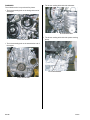
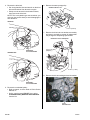
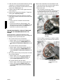
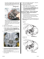
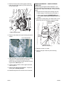
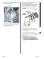
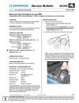
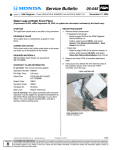
Service Bulletin
Applies To:
06-020
April 6, 2007
2006 Civic – See VEHICLES AFFECTED
Engine Oil Leaks and Power Steering Fluid Leak
(Supersedes 06-020, dated June 20, 2006, to update the information marked by the black bars)
SYMPTOM
The engine leaks oil, or the power steering inlet pipe
leaks fluid.
WARRANTY CLAIM INFORMATION
In warranty: The normal warranty applies.
OP#
PROBABLE CAUSE
Some engine block sealing bolts may have been
mismanufactured, causing the engine oil to leak when
the engine is running. The power steering inlet pipe
may have been mismanufactured, causing a power
steering leak.
VEHICLES AFFECTED
2006 Civic
4-Door – From VIN 1HGFA1...6L000001
thru 1HGFA1...6L058027
Description
111155
Repair Procedure A
0.9
111156
Repair Procedure B (A/T-equipped)
4.9
111157
Repair Procedure B (M/T-equipped)
5.1
111158
Repair Procedure C
1.2
111159
Repair Procedure D
1.0
512116
Repair Procedure E
(Submit a separate warranty claim for this
repair.)
0.4
Failed Part:
From VIN 2HGFA1...6H500001
thru 2HGFA1...6H505400
2-Door – From VIN 2HGFG1...6H500001
thru 2HGFG1...6H523216
CORRECTIVE ACTION
Replace the affected engine block sealing bolt(s) and
washer(s), and/or replace the power steering pump
inlet pipe, O-ring, and hose clamp.
Sealing Bolt (24 mm):
P/N 11107-RNA-A00, H/C 8160657
P/N 11107-RNA-A00,
H/C 8160657
(Repair Procedures A and B)
P/N 11106-RNA-A00,
H/C 8160640
(Repair Procedures C and D)
From VIN JHMFA1...6S000001
thru JHMFA1...6S005042
PARTS INFORMATION
Drive Belt Auto Tensioner Bolt:
P/N 96700-10055-18, H/C 8114506
FRT
P/N 56123-RNA-A01,
H/C 8051088
(Repair Procedure E)
Defect Code:
07701
Symptom Code:
05101
Skill Level:
Repair Technician
Out of warranty: Any repair performed after warranty
expiration may be eligible for goodwill consideration by
the District Parts and Service Manager or your Zone
Office. You must request consideration, and get a
decision, before starting work.
Sealing Washer (24 mm):
P/N 11107-PWA-300, H/C 7006919
Sealing Bolt (20 mm):
P/N 11105-RNA-A00, H/C 8160632
Washer (20 mm):
P/N 11106-RNA-A00, H/C 8160640
Transmission End Crankshaft Oil Seal:
P/N 91214-RTA-004, H/C 8113060
Inlet Pipe:
P/N 56123-RNA-A01, H/C 8051088
O-Ring:
P/N 91345-PAA-A01, H/C 5430681
Hose Clamp:
P/N 19513-REA-Z01, H/C 8570624
© 2007 American Honda Motor Co., Inc. – All Rights Reserved
ATB 31857-34693 (0704)
1 of 10
CUSTOMER INFORMATION: The information in this bulletin is intended for use only by skilled technicians who have the proper tools, equipment,
and training to correctly and safely maintain your vehicle. These procedures should not be attempted by “do-it-yourselfers,” and you should not assume
this bulletin applies to your vehicle, or that your vehicle has the condition described. To determine whether this information applies, contact an
authorized Honda automobile dealer.
DIAGNOSIS
• The 20-mm sealing bolt behind the alternator.
The oil leaks can be in up to these five places:
• The 24-mm sealing bolt on the timing chain end of
the engine.
20-mm SEALING BOLT
24-mm SEALING BOLT
• The 20-mm sealing bolt behind the power steering
pump.
• The 24-mm sealing bolt on the transmission end of
the engine.
20-mm SEALING BOLT
24-mm SEALING BOLT
2 of 10
06-020
• The inlet pipe on the power steering pump.
PUMP INLET HOSE
Repair
Procedure
D
INLET PIPE
Description
Replace the 20-mm sealing bolt behind the
power steering pump.
From VIN 1HGFA1...6L000001 thru
1HGFA1...6L025717
From VIN 2HGFA1...6H500001 thru
2HGFA1...6H505400
From VIN 2HGFG1...6H500001 thru
2HGFG1...6H523216
From VIN JHMFA1...6S000001 thru
JHMFA1...6S005042
E
Replace the inlet pipe on the power steering
pump.
From VIN 1HGFA1...6L000001 thru
1HGFA1...6L058027
From VIN 2HGFA1...6H500001 thru
2HGFA1...6H516515
From VIN 2HGFG1...6H500001 thru
2HGFG1...6H501591
From VIN JHMFA1...6S000001 thru
JHMFA1...6S005042
Inspect the leaking area(s), then use the chart to
determine the appropriate repair procedures.
Repair
Procedure
A
Description
Replace the 24-mm sealing bolt on the
timing chain end of the engine.
From VIN 1HGFA1...6L000001 thru
1HGFA1...6L020977
From VIN 2HGFA1...6H500001 thru
2HGFA1...6H502850
From VIN 2HGFG1...6H500001 thru
2HGFG1...6H520655
From VIN JHMFA1...6S000001 thru
JHMFA1...6S005042
B
NOTE: The sealing bolts leak very little oil so you can
miss the oil leak if you don’t look carefully. Often the oil
runs down the engine and accumulates in other places,
leading to misdiagnosis and failure to repair the leak.
REPAIR PROCEDURE A - REPLACE THE 24-MM
SEALING BOLT ON THE TIMING CHAIN END OF
THE ENGINE
1. Raise the vehicle on a hoist.
2. Remove the right front tire.
3. Remove the splash shield.
FRONT
BUMPER
FRONT INNER FENDER
Replace the 24-mm sealing bolt on the
transmission end of the engine.
From VIN 1HGFA1...6L000001 thru
1HGFA1...6L020977
From VIN 2HGFA1...6H500001 thru
2HGFA1...6H502850
From VIN 2HGFG1...6H500001 thru
2HGFG1...6H520655
From VIN JHMFA1...6S000001 thru
JHMFA1...6S005042
C
From VIN 1HGFA1...6L000001 thru
1HGFA1...6L025717
From VIN 2HGFA1...6H500001 thru
2HGFA1...6H505400
From VIN 2HGFG1...6H500001 thru
2HGFG1...6H523216
From VIN JHMFA1...6S000001 thru
JHMFA1...6S005042
06-020
FRONT
INNER
FENDER
Replace the 20-mm sealing bolt behind the
alternator.
SPLASH SHIELD
HOOK
3 of 10
4. Remove the drive belt:
• Set a long-handled, box-end wrench on the drive
belt auto-tensioner from above the engine.
6. Remove the water pump pulley.
WATER PUMP PULLEY
• Slowly turn the wrench in the direction shown,
then remove the drive belt.
NOTE: This is a hydraulic type auto-tensioner; you
must turn the wrench slowly to avoid damaging the
auto-tensioner.
WITH A/C
14 N.m (10 lb-ft)
7. Remove the drive belt auto tensioner assembly,
and store it vertically to prevent oil leakage that
may change the dampening specification.
DRIVE BELT AUTO TENSIONER
WITHOUT A/C
DRIVE BELT
AUTO-TENSIONER
54 N.m (40 lb-ft)
(Replace.)
24 N.m (17 lb-ft)
8. Remove the 24-mm sealing bolt and its washer.
DRIVE BELT
AUTO-TENSIONER
5. Remove the crankshaft pulley:
• Refer to page 6-10 of the 2006–07 Civic Service
Manual, or
• Online, enter keyword PULLEY, then select
Crankshaft Pulley Removal and Installation
from the list.
24-mm
SEALING BOLT
4 of 10
06-020
9. Clean the sealer out of the block threads by running
a pick tool or a toothbrush along the threads.
NOTE: Pull any material from the threads out of the
engine block. Do not push it in.
10. Coat the sealing surface on the engine block with
clean engine oil.
11. Install a new sealing bolt and washer. Torque the
sealing bolt to 60 N.m (45 lb-ft).
3. Remove the transmission end crankshaft oil seal:
• If you can see the leak, mark the location with a
paint marker before removing the seal.
• Remove the seal:
- Use a hammer to firmly tap a small,
4 x 20-mm Phillips-head sheet metal screw into
the metal part of the seal. If you marked the
leak location, make sure you tap the screw into
the seal directly across from the paint mark.
12. Reinstall the drive belt auto tensioner, the water
pump pulley, and the drive belt in the reverse order
of removal.
NOTE:
• Use a new bolt ot install the drive belt auto
tensioner.
• The bolt is located in a dfficult location. Use
Snap-on 8 mm hex socket (T/N FAM8E) and 3/8
flex ratchet torque wrench (T/N QD2FR75), or
equivalent, to properly torque the bolt.
REPAIR PROCEDURE B - REPLACE THE 24-MM
BOLT ON THE TRANSMISSION END OF THE
ENGINE
NOTE: Because it is difficult to determine if the
transmission end crankshaft oil seal or the sealing bolt
is causing the leak, replace both parts.
1. M/T models: Remove the transmission.
• Refer to page 13-7 of the service manual, or
• Online, enter keywords TRANS REMOV and
select Manual Transmission Removal from the
list.
TRANSMISSION
END CRANKSHAFT
OIL SEAL
- Use a cordless screwdriver or another suitable
tool to firmly drive the screw into the oil seal so
it won’t come out.
A/T models: Remove the transmission.
• Refer to page 14-236 of the service manual, or
• Online, enter keywords TRANS REMOV and
select Automatic Transmission Removal from
the list.
2. M/T models: Remove the pressure plate, the clutch
disc, and the flywheel.
• Refer to page 12-17 of the service manual, or
• Online, enter keywords PRESS PLATE and
select Clutch Replacement from the list.
A/T models: Remove the drive plate.
• Refer to page 14-256 of the service manual, or
• Online, enter keywords DRIVE PLATE and
select Drive Plate Removal and Installation
from the list.
06-020
CORDLESS DRILL
(Carefully drive in the
screw.)
5 of 10
- Use a pair of diagonal cutters to grip the screw
under its head. While carefully prying up with
the cutters, grab the screw with your other hand
and gently pull out the seal.
DIAGONAL CUTTERS
(Pry out oil seal.)
9. Install a new sealing bolt and washer. Torque the
sealing bolt to 54 N.m (40 lb-ft).
10. Reinstall the transmission:
• Refer to page 13-13 (M/T models), or 14-246
(A/T models) of the service manual, or
• Online, enter keywords TRANS INSTALL, and
select Manual Transmission Installation (M/T
models) or Automatic Transmission
Installation (A/T models) from the list.
REPAIR PROCEDURE C - REPLACE THE 20-MM
SEALING BOLT BEHIND THE ALTERNATOR
1. Remove the drive belt:
• Set a long-handled, box-end wrench on the drive
belt auto-tensioner from above the engine.
• Slowly turn the wrench in the direction shown,
then remove the drive belt.
- Slip the seal (with the screw attached) into a
resealable plastic bag. Avoid touching any
surfaces that may have contamination on them.
- Tag the plastic bag, and set it on the warranty
parts shelf.
NOTE: This is a hydraulic type auto-tensioner; you
must turn the wrench slowly to avoid damaging the
auto-tensioner.
WITH A/C
4. Clean the oil off the engine.
5. Install a new transmission end crankshaft oil seal:
• Refer to page 7-33 of the service manual, or
• Online, enter the keywords TRANS SEAL and
select Transmission End Crankshaft Oil Seal
Installation - in car from the list.
6. Remove the 24-mm sealing bolt and its washer.
WITHOUT A/C
DRIVE BELT
AUTO-TENSIONER
24-mm SEALING BOLT
7. Clean the sealer out of the block threads by running
a pick tool or a toothbrush along the threads.
NOTE: Pull any material from the threads out of the
engine block. Do not push it in.
8. Coat the sealing surface on the engine block with
clean engine oil.
6 of 10
DRIVE BELT
AUTO-TENSIONER
06-020
2. Remove the alternator. Do not disconnect its
electrical connections, or damage the wires:
• Refer to page 4-44 of the service manual, or
• Online, enter keyword ALT, and select
Alternator Removal and Installation from the
list.
7. Remove the original sealing bolt and its washer.
8. Clean the sealer out of the block threads by running
a pick tool or a toothbrush along the threads.
NOTE: Pull any material from the threads out of the
engine block. Do not push it in.
3. Drain the engine coolant.
9. Coat the sealing surface on the engine block with
clean engine oil.
4. Remove the EGR pipe from the thermostat
housing.
10. Install a new sealing bolt and washer. Torque the
sealing bolt to 34 N.m (25 lb-ft).
11. Reinstall the parts in the reverse order of removal.
12. Refill the radiator, then bleed the cooling system.
REPAIR PROCEDURE D - REPLACE THE 20-MM
BOLT BEHIND THE POWER STEERING PUMP
Verify if the oil leak is from the oil sealing bolt or the
power steering system:
• Oil leaks from the 20-mm sealing bolt tend to collect
on the lower engine block and oil pan.
• Oil leaks from the right rear cover of the power
steering pump tend to collect on the pump, but not
on the pump inlet pipe.
EGR PIPE
THERMOSTAT HOUSING
5. Remove the EGR pipe and thermostat housing
from the cylinder head.
6. Disconnect the water pipe, then lower it so you can
access the 20-mm sealing bolt.
• Oil leaks from the power steering pump inlet pipe
tend to collect on the inlet pipe, but are not found on
the right rear cover of the power steering pump.
If the power steering system is leaking from the inlet
pipe area, go to REPAIR PROCEDURE E - POWER
STEERING PUMP LEAK. For other power steering
leaks, refer to the service manual.
1. Remove the cowl cover.
• Refer to page 20-229 of the service manual, or
• Online, enter keyword COWL, then select Cowl
Cover Replacement from the list.
2. Remove the drive belt:
• Set a long-handled, box-end wrench on the drive
belt auto-tensioner from above the engine.
• Slowly turn the wrench in the direction shown,
then remove the drive belt.
20-mm SEALING BOLT
06-020
WATER PIPE
7 of 10
NOTE: This is a hydraulic type auto-tensioner;
you must turn the wrench slowly to avoid
damaging the auto-tensioner.
3. Disconnect the power steering pump inlet hose
from its holder on the right inner strut tower.
WITH A/C
POWER STEERING
PUMP INLET HOSE
(Unclip.)
WITHOUT A/C
DRIVE BELT
AUTO-TENSIONER
DRIVE BELT
AUTO-TENSIONER
4. Remove the pump outlet hose bracket from the
back of the intake manifold.
PUMP OUTLET HOSE POWER
STEERING MOUNTING BRACKET
(Unbolt.)
8 of 10
06-020
5. Remove the two power steering pump mounting
bolts, then lower the pump so you can access the
20-mm sealing bolt.
REPAIR PROCEDURE E - POWER STEERING
PUMP LEAK
NOTE: During an engine oil leak inspection, if you
discover the power steering pump is leaking from the
inlet pipe area, replace the inlet pipe, O-ring, and hose
clamp.
1. Drain the fluid from the power steering reservoir.
• Refer to page 17-30 of the service manual, or
• Online, enter keywords POWER FLUID, then
select Power Steering Fluid Replacement from
the list.
2. Squeeze the spring clamp, and slide it back on the
pump inlet hose so it clears the reservoir spigot.
POWER STEERING
RESERVOIR
POWER STEERING PUMP
6. Remove and discard the original sealing bolt and its
washer.
20-mm SEALING BOLT
PUMP INLET HOSE
(Slide the clamp down.)
3. Raise the vehicle on a hoist.
4. Place a drain pan under the power steering
reservoir.
7. Clean the sealer out of the block threads by running
a pick tool or a toothbrush along the threads.
NOTE: Pull any material from the threads out of the
engine block. Do not push it in.
8. Coat the sealing surface on the engine block with
clean engine oil.
9. Install a new sealing bolt and washer. Torque the
sealing bolt to 34 N.m (25 lb-ft).
10. Reinstall the parts in the reverse order of removal.
06-020
9 of 10
5. Remove the 10-mm bolt that attaches the inlet pipe
to the power steering pump.
PUMP INLET HOSE
INLET PIPE
7. On your workbench, replace the inlet pipe, O-ring,
and hose clamp with new parts.
NOTE: The pump inlet hose is shown attached to
the power steering pump to show the proper
position of the clamp. Position the clamp directly in
front of the ridge on the inlet pipe before
installation. It is easier to set the clamp before
installation.
INLET HOSE
Center the clamp
on this ridge.
POWER
STEERING
PUMP
2 to 3 mm
6. Lower the vehicle, then remove the pump inlet hose
from the reservoir. Remove the pump inlet hose
and inlet pipe from the vehicle.
8. Attach the pump inlet hose to the reservoir.
9. Install the inlet pipe on the power steering pump.
• Raise the vehicle.
• Install a new O-ring on the inlet pipe.
• Coat the O-ring with clean power steering fluid.
10. Install the 10-mm bolt. Torque the 10-mm bolt to
10 N.m (8 lb-ft).
11. Lower the vehicle, then fill the reservoir.
• Refer to page 17-30 of the service manual, or
• Online, enter keywords POWER FLUID, then
select Power Steering Fluid Replacement from
the list.
10 of 10
06-020