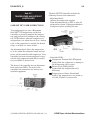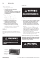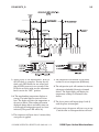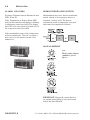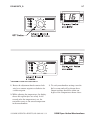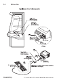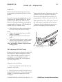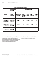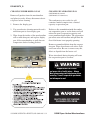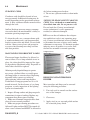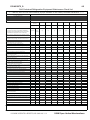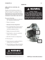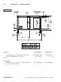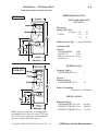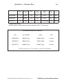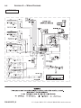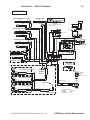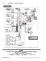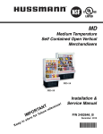
1
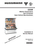
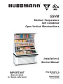
®
Merchandisers
GSVM
Medium Temperature
Self Contained
Open Vertical Merchandisers
Installation &
Service Manual
IMPORTANT
Keep in store
for future reference!
P/N 0515275_G
October 2013
Spanish 0531285
French 0531286
P/N 0515275_G
iii
IMPORTANT
KEEP IN STORE FOR FUTURE REFERENCE
Quality that sets industry standards!
12999 St. Charles Rock Road • Bridgeton, MO 63044-2483
U.S. & Canada 1-800-922-1919 • Mexico 01 800-890-2900
www.hussmann.com
© 2013 Hussmann Corporation
TABLE OF CONTENTS
ANSI DEFINITIONS . . . . . . . . . . . . . . . . . vi
MAINTENANCE
INSTALLATION
Care and Cleaning . . . . . . . . . . . . . . . . . . . Do NOT Use: . . . . . . . . . . . . . . . . . . . . . . Do: . . . . . . . . . . . . . . . . . . . . . . . . . . . . . . . Removing Scratches from Bumper . . . . . . Cleaning Discharge Honeycomb . . . . . . . Cleaning Under Display Pan . . . . . . . . . . Cleaning Evaporation Pan . . . . . . . . . . . . Cleaning Coils . . . . . . . . . . . . . . . . . . . . . . Removing Scratches from Bumper . . . . . . Maintaining Fluorescent Lamps . . . . . . . . Certification . . . . . . . . . . . . . . . . . . . . . . . . Hussmann Product Control . . . . . . . . . . . Shipping Damage . . . . . . . . . . . . . . . . . . . Location . . . . . . . . . . . . . . . . . . . . . . . . . . . Self Contained Location . . . . . . . . . . . . . . Model Description . . . . . . . . . . . . . . . . . . Unloading . . . . . . . . . . . . . . . . . . . . . . . . . Exterior Loading . . . . . . . . . . . . . . . . . . . . Shipping Skid . . . . . . . . . . . . . . . . . . . . . . Merchandiser Leveling . . . . . . . . . . . . . . . Optional Legs . . . . . . . . . . . . . . . . . . . . . . Serial Plate Location . . . . . . . . . . . . . . . . . Refrigeration Unit Access . . . . . . . . . . . . . Sealing Merchandiser to Floor . . . . . . . . . Night Curtain Installation . . . . . . . . . . . . Checklists . . . . . . . . . . . . . . . . . . . . . . . . . . 1-1
1-1
1-1
1-1
1-2
1-3
1-3
1-3
1-3
1-4
1-4
1-4
1-4
1-4
1-5
1-7
ELECTRICAL / REFRIGERATION
Merchandiser Electrical Data . . . . . . . . . . Field Wiring . . . . . . . . . . . . . . . . . . . . . . . . Power Switch . . . . . . . . . . . . . . . . . . . . . . . Electrical Connections . . . . . . . . . . . . . . . .
Electrical Outlet . . . . . . . . . . . . . . . . . . . . . Refrigeration (Self Contained) . . . . . . . . . Waste Outlet and Water Seal . . . . . . . . . . Safe-NET III Controller . . . . . . . . . . . . . . Safe-NET Display . . . . . . . . . . . . . . . . . . . Safe-NET Start-Up . . . . . . . . . . . . . . . . . . Sequence of Operation . . . . . . . . . . . . . . . Alarms and Codes . . . . . . . . . . . . . . . . . . . Defrost Termination Switch . . . . . . . . . . . Temperature Adjustment . . . . . . . . . . . . . 2-1
2-1
2-1
2-1
2-1
2-2
2-2
2-3
2-4
2-4
2-5
2-6
2-6
2-7
v
4-1
4-1
4-1
4-2
4-2
4-3
4-3
4-4
4-4
4-4
SERVICE
Replacing Fan Motors and Blades . . . . . . Replacing Fluorescent Lamps . . . . . . . . . Repairing Aluminum Coil . . . . . . . . . . . . Troubleshooting Guide . . . . . . . . . . . . . . . GSVM Accessories . . . . . . . . . . . . . . . . . . Definitions . . . . . . . . . . . . . . . . . . . . . . . . . 5-1
5-2
5-2
5-3
5-4
5-5
APPENDIX
Part Numbers . . . . . . . . . . . . . . . . . . . . . .
Plan View . . . . . . . . . . . . . . . . . . . . . . . . . .
Cross Sections and Refrigeration Data. . .
Electrical Data . . . . . . . . . . . . . . . . . . . . . .
Shipping Weights and Amps . . . . . . . . . .
Wiring Diagram GSVM-4060 . . . . . . . . . .
Wiring Diagram GSVM-4072 . . . . . . . . . .
Wiring Diagram GSVM-5272 . . . . . . . . . .
A-1
A-2
A-3
A-4
A-5
A-6
A-7
A-8
WARRANTY
START UP / OPERATION
Start-Up . . . . . . . . . . . . . . . . . . . . . . . . . . . TEV Adjustment . . . . . . . . . . . . . . . . . . . . Controls and Adjustments . . . . . . . . . . . . Load Limits . . . . . . . . . . . . . . . . . . . . . . . . Stocking . . . . . . . . . . . . . . . . . . . . . . . . . . . Solar Thermometer . . . . . . . . . . . . . . . . . . Shelf Weight Limits . . . . . . . . . . . . . . . . . . 3-1
3-1
3-2
3-3
3-3
3-3
3-4
HUSSMANN CORPORATION • BRIDGETON, MO 63044-2483 U.S.A.
GSVM Open Vertical Merchandisers
vi
REVISION HISTORY
REVISION G — Added Checklists Page 1-7; Added
Warning Page 1-3; Cleaning Coils 4-4; Maintaining
Fluorescent Lights 4-4. Checklist 4-5
REVISION F — JULY 2013
1. Included Night Curtain Instructions, Page 1-5 and 1-6
2. Added Night Curtain Description, Page 5-5
REVISION E — FEBRUARY 2012
1. Revised Nema Plug, Page 2-1
REVISION D — JANUARY 2012
1. Revised for Wind Chill
REVISION C — JANUARY 2012
1. Removed Remote Models
2. Added Safe-NET III
3. Revised Wiring Diagrams
**************************
REVISION B — DECEMBER 2010
1. Added option condensate pan for GSVM 4072 and 5272; Page, 2-2
2. Replaced Bulb illustration; Page 5-2
3. Updated wiring diagram; Page A-11
ORIGINAL ISSUE — NOVEMBER 2010
ANSI Z535.5 DEFINITIONS
• DANGER – Indicate[s] a hazardous
situation which, if not avoided, will
result in death or serious injury.
• WARNING – Indicate[s] a hazardous
situation which, if not avoided, could
result in death or serious injury.
• CAUTION – Indicate[s] a hazardous
situation which, if not avoided, could
result in minor or moderate injury.
• NOTICE – Not related to personal injury –
Indicates[s] situations, which if not avoided,
could result in damage to equipment.
P/N 0515275_G
U.S. & Canada 1-800-922-1919 • Mexico 01 800-890-2900 • www.hussmann.com
P/N 0515275_G
1-1
INSTALLATION
CERTIFICATION
These merchandisers are manufactured to
meet ANSI / National Sanitation Foundation
(NSF® ) Standard #7 requirements. Proper
installation is required to maintain certification.
Near the serial plate, each case carries a label
identifying the type of application for which
the case was certified.
Apparent Loss or Damage
If there is an obvious loss or damage, it must
be noted on the freight bill or express receipt
and signed by the carrier’s agent; otherwise,
carrier may refuse claim.
Concealed Loss or Damage
ANSI/NSF-7 Type I - Display Refrigerator / Freezer
Intended for 75°F / 55% RH Ambient Application
ANSI/NSF-7 Type II - Display Refrigerator / Freezer
Intended for 80°F / 55% RH Ambient Application
When loss or damage is not apparent until
after equipment is uncrated, retain all packing
materials and submit a written response to the
carrier for inspection within 15 days.
ANSI/NSF-7 - Display Refrigerator
Intended for Bulk Produce
HUSSMANN PRODUCT CONTROL
The serial number and shipping date of all
equipment is recorded in Hussmann’s files
for warranty and replacement part purposes.
All correspondence pertaining to warranty or
parts ordering must include the serial number
of each piece of equipment involved. This is to
ensure the customer is provided with the correct parts.
SHIPPING DAMAGE
All equipment should be thoroughly examined
for shipping damage before and during
unloading. This equipment has been carefully
inspected at our factory. Any claim for loss
or damage must be made to the carrier. The
carrier will provide any necessary inspection
reports and/or claim forms.
HUSSMANN CORPORATION • BRIDGETON, MO 63044-2483 U.S.A.
LOCATION
These merchandisers are designed for
displaying products in air conditioned stores
where temperature is maintained at or below
the ANSI / NSF-7 specified level and relative
humidity is maintained at or below 55%.
Recommended operating ambient
temperature is between
65°F (18°C) to 80°F (26.6°C).
Maximum relative humidity is 55%.
Placing refrigerated merchandisers in direct
sunlight, near hot tables or near other heat
sources could impair their efficiency. Like
other merchandisers, these merchandisers are
sensitive to air disturbances. Air currents
passing around merchandisers will seriously
impair their operation. Do NOT allow air
conditioning, electric fans, open doors or
windows, etc. to create air currents around the
merchandiser.
GSVM Open Vertical Merchandisers
1-2
Installation
SELF CONTAINED (LOCATION)
G SVM
G SVM
GSVM-4060 and GSVM-4072 (at 75°F/55%
relative humidity, maximum ambient conditions) has front condenser air intake and discharge. Maintain a minimum clearance distance
of two feet in front of the merchandiser so that
air discharge and air intake is not obstructed.
GSVM-4072 (at 80°F/55% relative humidity,
maximum ambient conditions) and
GSVM-5272 each require a 5 inch minimum
clearance behind the merchandiser and clearance above the merchandiser since its air flows
straight through the condensing unit compartment. Brackets are provided for field attachment
to obtain this rear 5 inch minimum clearance.
G SVM -5272
G SVM -4072
P/N 0515275_G
U.S. & Canada 1-800-922-1919 • Mexico 01 800-890-2900 • www.hussmann.com
P/N 0515275_G
1-3
MODEL DESCRIPTION
SHIPPING SKID
The GSVM open vertical merchandiser offers
versatility in the display of medium temperature
(32º F to 41º F) products such as dairy products,
prepared salads, pizza and fresh entrees that
are pre-chilled in a cooler. Carefully read and
follow the instructions prior operating the merchandiser.
Each merchandiser is shipped on a skid to
protect the merchandiser’s base, and to make
positioning the case easier.
UNLOADING
Unloading from Trailer:
Lever Bar (also known as a Mule, Johnson
Bar, J-bar, Lever Dolly, or Pry Lever)
Move the merchandiser as close as possible to
its permanent location and remove all packaging.
Check for damage before discarding packaging.
Remove all separately packed accessories such
as kits and shelves. Improper handling may
cause damage to the merchandiser when unloading. To avoid damage:
Do not walk or put heavy objects on case.
1. Do not drag the merchandiser out of the trailer. Use a Johnson bar (mule).
2. Use a forklift or dolly to remove the
merchandiser from the trailer.
EXTERIOR LOADING
Do not remove the shipping skid until the
merchandiser is near its final location. The
skid provides protection for both the merchandiser and the floor.
Remove the skid by raising one end of the
merchandiser approximately 6 inches. Block the
merchandiser securely, and remove the two skid
bolts from the raised end. Replace the bolts
with (provided) leg levelers. Repeat this procedure at opposing end. Once the leg levelers are
secured in place, the merchandiser may be slid
off the skid and placed in its final location.
DO NOT TILT MERCHANDISER ON ITS
SIDE OR END WHEN REMOVING SKID.
Once the skid is removed, the merchandiser
must be lifted —NOT PUSHED— to reposition.
Check floor where merchandisers are to be set
to see if it is a level area. Determine the highest
part of the floor.
Do NOT remove shipping crate until the
merchandiser is positioned
for installation.
Do NOT walk on top of merchandisers or
damage to the merchandisers and serious
personal injury could occur.
merchandisers are not structurally
designed to support external loading
such as the weight of a person. Do not place
heavy objects on the merchandiser.
HUSSMANN CORPORATION • BRIDGETON, MO 63044-2483 U.S.A.
Do NOT stand or walk on top of
merchandiser. Do not store items or
flammable materials atop the unit.
GSVM Open Vertical Merchandisers
1-4
Installation
MERCHANDISER LEVELING
REFRIGERATION UNIT ACCESS
Be sure to position merchandisers properly. Level the merchandiser by all four corners.
Merchandiser(s) must be installed level to
ensure proper operation of the refrigeration
system, and to ensure proper drainage of
defrost water.
The lower front panel may be removed by
removing screw at bottom and lifting the panel
straight upward and over the tabs on which it
is hanging. The panel is installed by reversing the
above procedure.
Ensure lower front panel is flat against the
floor when installed to prevent air circulation
problems for self contained merchandisers.
OPTIONAL LEGS
NSF® approved legs replace the leg levelers if
required by local health codes. The legs raise
the case 6 inches for cleaning purposes. An
optional skirt kit can be provided to snap on
the legs.
SERIAL PLATE LOCATION
The serial plate is located on the interior top,
left side of the merchandiser. It contains all
pertinent information such as model, serial
number, amperage rating, refrigerant type and
charge. This information will be needed to
install, service or order parts for the merchandiser.
Safe-NET III Display
Front Panel
Lift up and
out to remove
access panel
Safe-NET III display is
mounted on left side of
access panel. Be careful not
to detach Safe-NET III cable
from display when removing
access panel.
Safe-NET III
Display
SEALING MERCHANDISER TO FLOOR
Serial Plate
If required by local sanitary codes, or if the
customer desires, merchandisers may be sealed
to the floor using a vinyl cove base trim. The
size needed will depend on how much variation there is in the floor, from one end of the
merchandiser to the other. Sealing of the lower
front and rear panels on self contained models may hamper their removal for servicing or
maintenance of the condensing unit.
NOTE: Do not allow trim to cover any intake
or discharge grilles located in the lower front
panel.
P/N 0515275_G
U.S. & Canada 1-800-922-1919 • Mexico 01 800-890-2900 • www.hussmann.com
P/N 0515275_G
1-5
NIGHT CURTAIN INSTALLATION
Night curtains are used to cover the case opening after normal business hours. The curtains
improve energy consumption, allowing the
refrigeration system to work less.
Fasten night curtain to top panel using (3) #8
x 1/2 in. screws.
Night Curtain
Carefully inspect the night curtain kit to
ensure there is no damage from breakage
during
shipping. Case should be positioned and
leveled before installing the night curtain.
Position night curtain on top panel. Measure
21 inches to edge of the end night curtain.
Center night curtain to length of case.
HUSSMANN CORPORATION • BRIDGETON, MO 63044-2483 U.S.A.
The night curtain for GSVM is standard
for model 5272 and is an optional kit for
models 4060 and 4072.
GSVM Open Vertical Merchandisers
1-6
Installation
Secure bottom of night curtain using bottom
clip as shown below. Clip is to be installed 2
in. in front access panel.
Bottom Clip
Night Curtain Installed
Front Access
Panel
Bottom Clip
P/N 0515275_G
A
U.S. & Canada 1-800-922-1919 • Mexico 01 800-890-2900 • www.hussmann.com
P/N 0515275_G
1-7
Hussmann Self-Contained Refrigeration Equipment Start Up Check List
***Please note that failure to follow this start-up document may void your factory warranty***
Step
Startup Activity
Check
1
Locate, read and maintain install/operation manual in a safe place for
future reference.
2
Examine unit. Confirm there is NO damage or concealed damage.
3
Level the unit, side to side and front to rear.
4
Remove all shipping brackets/compressor straps/bolts etc.
5
Unit must be run on a dedicated electrical circuit without the use of
an extension cord.
6
Ensure that the proper electrical requirements for the equipment are
supplied.
7
Verify field electrical connections are tight.
8
Verify all electrical wiring is secured and clear of any sharp edges or
hot lines.
9
Verify the condensate drain line is properly trapped and pitched.
10
Verify all required clearances on the sides and back of unit.
11
Verify there are no air disturbances external to the unit. Heat and air
registers, fans, and doors etc.
Advise owner/operator that merchandiser must operate at temperature for 24 hrs prior to loading
with product.
Form HSCW01 Rev. 30MAY12 P/N 0525209_B
LEGAL DISCLAIMER:
Hussmann shall not be liable for any repair or replacements made without the written consent of Hussmann, or when the product is installed or operated in a manner
contrary to the printed instructions covering installation and service which accompanied such product.
HUSSMANN CORPORATION • BRIDGETON, MO 63044-2483 U.S.A.
GSVM Open Vertical Merchandisers
1-8
Installation
NOTES:
P/N 0515275_G
U.S. & Canada 1-800-922-1919 • Mexico 01 800-890-2900 • www.hussmann.com
P/N 0515275_G
2-1
ELECTRICAL / REFRIGERATION
MERCHANDISER ELECTRICAL DATA
ELECTRICAL OUTLET:
Refer to Appendix A of this manual or the
merchandiser’s serial plate for electrical
information.
Before the merchandiser is connected to any
wall circuit, use a voltmeter to check that the
outlet is at 100% of the rated voltage. The wall
circuit must be dedicated for the merchandiser. Failure to do so voids the warranty. Do
not use an extension cord. Never plug in more
than one merchandiser per electrical circuit.
FIELD WIRING
Field wiring must be sized for component
amperes stamped on the serial plate. Actual
ampere draw may be less than specified.
ALWAYS CHECK THE SERIAL PLATE FOR
COMPONENT AMPERES
ELECTRICAL CONNECTIONS
All wiring must be in compliance with NEC
and local codes. All electrical connections for
GSVM-5072 self-contained are to be made in
the electrical Handy Box located behind the
removable base panel at the left end of the
merchandiser when facing the discharge air
honeycomb. GSVM-4060 and GSVM-4072 is
provided with a power cord.
• Always use a dedicated circuit with the
amperage stated on the unit.
• Plug into an outlet designed for the plug.
• Do not overload the circuit
• Do not use long or thin extension cords.
Never use adapters.
• If in doubt, call an electrician.
NEMA 5-20R
Receptacle
GSVM-4060
GSVM-4072
GSVM-4060 and
GSVM-4072 has a
factory-installed power
cord that is attached at
the electrical box.
POWER SWITCH
The main electrical power switch is located
behind the front louvered access panel. The
power switch must be turned OFF before
servicing the merchandiser.
— LOCK OUT / TAG OUT —
To avoid serious injury or death from electrical shock, always disconnect the electrical
power at the main disconnect when servicing
or replacing any electrical component. This
includes, but is not limited to, such items as
doors, lights, fans, heaters, and thermostats.
HUSSMANN CORPORATION • BRIDGETON, MO 63044-2483 U.S.A.
Risk of Electric Shock. If cord or plug
becomes damaged, replace only with
a cord and plug of the same type.
Merchandiser must be grounded.
Do not remove the power supply cord ground.
GSVM Open Vertical Merchandisers
2-2
Installation
WATER OUTLET AND WATER SEAL
REFRIGERATION
(Self Contained Models)
Each self contained model is equipped with
its own condensing unit and control panel
located beneath the display area. The correct
type of refrigerant will be stamped on each
merchandiser’s serial plate. The merchandiser refrigeration piping is leak tested. The
unit is charged with refrigerant, and shipped
from the factory with all service valves open.
GSVM models have a refrigeration system
that uses a hermetic compressor. GSVM-4060
and GSVM-4072 systems use a capillary tube
for refrigerant control. The capillary tube is
soldered to the suction line pull-out coil for
proper heat exchange. If the capillary should
become plugged or damaged, it is best to replace
the heat exchanger.
GSVM-5272 employs a bleed port type
expansion valve for proper refrigerant
control. Read the merchandiser’s serial plate
for the appropriate refrigerant type and
weight.
GSVM models 4072 and 5272 require a floor
drain. The condensate water outlet is located
in the center of the merchandiser. The outlet
has a factory installed, external water seal.
For self contained models like GSVM-4060,
this water seal drains into a high-humidity
electric condensate pan located beneath the
merchandiser. The pan uses a thermistor that
senses water in the pan, adjusting the amount
of heat required to evaporate the water. Ensure
the drain hose is properly trapped, and the drain
area is not clogged.
NOTE: All lower base panels must be in place
when the refrigerator is operating. If not, airflow
from the condenser will be directed over the evaporator pan and defrost water in the pan may overflow.
OPTIONAL ELECTRIC
CONDENSATE PAN
An optional high-humidity condensate pan
kit requires a dedicated 15 Amp circuit - 120V
(GSVM-4072 and GSVM-5272).
Oil Traps
P-traps (oil traps) must be installed at the base
of all suction line vertical risers.
Pressure Drop
Keep refrigerant line runs as short as possible
to avoid large pressure drops. Use a minimum
number of elbows. Where elbows are required,
use long radius elbows only.
P/N 0515275_G
U.S. & Canada 1-800-922-1919 • Mexico 01 800-890-2900 • www.hussmann.com
P/N 0515275_G
Safe-III™
TEMPERATURE AND DEFROST
CONTROLLER
SAFE-NET III™ USER INSTRUCTIONS
2-3
The Safe-NET III controller includes the
following features and connections.
• Adjustment knob:
Adjusts the temperature setpoint.
Turn adjustment knob to OFF to turn off
refrigeration system. Unplug merchandiser
from power before servicing the unit.
Your refrigerated case uses a Hussmann
Safe-NET™ III temperature and defrost
controller to precisely maintain the temperature and prevent frost buildup on the cooling
coil. LEDs indicate when the compressor or
refrigeration is on, when the case is in a defrost
cycle, if the temperature is outside the desired
range, or if there is a sensor failure.
An adjustment knob allows the temperature
to be set within the configured range and can
power off the controller and compressor. Your
controller has been custom-configured to provide the best temperature and defrost control
for your chilled or frozen food.
The front of the controller has an adjustment
knob and status LEDs. The back of the
controller has connections for sensors and
switched equipment.
HUSSMANN CORPORATION • BRIDGETON, MO 63044-2483 U.S.A.
• Controller LEDs:
Compressor Powered On LED (green):
Lights while the compressor is running or
the refrigeration valve is open.
Defrost Cycle LED (yellow):
Lights while the refrigeration coil is
defrosting.
Temperature or Sensor Alarm (red):
Lights if the temperature is too warm or
too cold. Flashes if a sensor fails.
GSVM Open Vertical Merchandisers
2-4
Installation
START-UP
• Rear connections:
– Case temperature sensor:
• Typically senses the temperature
of the air in the case.
Used by the controller to determine when
to power on or power off the compressor
or refrigeration.
– Evaporator temperature sensor:
• Senses the temperature of the
refrigeration coil.
Terminates a defrost cycle when
refrigeration coil ice melts.
– Compressor or refrigeration relay:
• Switches on the compressor or
refrigeration valve for cooling.
– Defrost / reversing condenser switch
• Swtiches on the defrost or reversing
condenser fan motor - when used with
the condenser fan motor option.
DISPLAY
The display includes three red LEDs and two
digits for temperature, defrost status, and error
codes.
The OFF Position does not disconnect line
voltage to the case, refrigeration unit, fan,
or heater.
1. Plug in the merchandiser.
2. Wait for the self check to complete. During
the self check, each LED flashes for one
second, then all LEDs turn on for two
seconds. If the LEDs do not flash, make
sure the adjustment knob is not in the Off
position.
• After the self check, all LEDs turn off
until the compressor starts. There may be
a delay before the compressor starts. If the
red Temperature or Sensor Alarm LED
stays on after the self check.
• The green Compressor Powered On LED
turns on when the compressor starts.
NOTE: Do NOT load product until AFTER
merchandiser operates for 24 hours and reaches
desired operating temperature.behavior matches the LEDs on the controller.
The optional evaporator fan remains ON
when the adjustment knob is in the OFF
position.
Product will be degraded and may spoil if
allowed to sit in a non-refrigerated area.
P/N 0515275_G
U.S. & Canada 1-800-922-1919 • Mexico 01 800-890-2900 • www.hussmann.com
P/N 0515275_G
1. Apply power to the merchandiser. Wait for
the self check to complete. During the self
check, each LED flashes for one second and
then all LEDs turn on for two seconds. If the
LEDs do not flash, make sure the adjustment
knob is not in the “OFF” position.
1A. The merchandiser temperature displays at
startup. The initial defrost starts two hours
later. The display will show the temperature at
the start of defrost. This reading will remain
displayed during defrost and until it times out,
even though the refrigeration mode has been
initiated. (The green LED will be lit.)
2-5
3. The compressor will continue to run until it
reaches its cut-out temperature (Pulldown).
4. The refrigeration cycle will continue for the next
subsequent scheduled (8-hours) or demand
defrost. The digital display will display the
temperature reading for 10 minutes after
defrost.
5. The above process will repeat (steps 3 and 4)
until the power is interrupted.
6. If power stops, the process will start over at step
1, and the time to subsequent defrost will reset.
2. The compressor will start after a 1-minute delay
once power is applied.
HUSSMANN CORPORATION • BRIDGETON, MO 63044-2483 U.S.A.
GSVM Open Vertical Merchandisers
2-6
Installation
ALARMS AND CODES
DEFROST TERMINATION SWITCH
Flashing Temperature or Sensor Alarm
LED, E1 or E2
If the Temperature or Sensor Alarm LED
(red) on the controller and display is flashing,
a temperature sensor has failed. The display
shows E1 if the case sensor has failed or E2 if
the evaporator sensor has failed.
Merchandisers may use a defrost termination
switch, instead of an evaporator sensor to
terminate a defrost cycle. The defrost
termination switch is temperature activated
and senses the completion of defrost.
If the merchandiser sensor fails, refrigeration
will run continuously. Turn off, or repeat a
duty cycle of a few minutes on and a few
minutes off.
MANUAL DEFROST
Note:
This procedure initiates
a manual or forced
defrost.
IMPORTANT: Return the control knob to
its original setting (Step 1) once the manual
defrost has been initiated.
P/N 0515275_G
U.S. & Canada 1-800-922-1919 • Mexico 01 800-890-2900 • www.hussmann.com
P/N 0515275_G
2-7
TEMPERATURE ADJUSTMENT
1. Rotate the adjustment knob counter clockwise for a warmer setpoint or clockwise for
a colder setpoint.
3. To verify merchandiser settings, turn the
dial to warm and cold as shown above.
Output readings should be within one
degree of the temperatures shown above.
2. While adjusting the temperature, the display
shows the setpoint (cut out value). A few
seconds after the temperature is set, the
controller reverts to the sensed temperature
in the merchandiser.
HUSSMANN CORPORATION • BRIDGETON, MO 63044-2483 U.S.A.
GSVM Open Vertical Merchandisers
2-8
Installation
P/N 0515275_G
U.S. & Canada 1-800-922-1919 • Mexico 01 800-890-2900 • www.hussmann.com
P/N 0515275_G
3-1
START UP / OPERATION
START UP
Follow the electromechanical controls start
up procedures as detailed in Section 2 of this
manual.
Each self contained merchandiser has its own
evaporator coil. Model GSVM-5272 has an
expansion valve (TEV). The TEV has been
factory set at design conditions to provide the
recommended performance. GSVM-4060 and
GSVM-4072 have capillary tubes.
Temperature (b) minus Temperature (a) is the
superheat. The valve should be adjusted so
that the greatest difference between the two
temperatures is 3° F (-16º C) to 5° F (-15º C).
Make adjustments of no more than 1/2 turn of
the valve stem at a time and wait for at least
15 minutes before rechecking the probe temperature and making further adjustments.
a. Check the interior cabinet thoroughly for
loose nuts, bolts and electrical connections.
b. Inspect the refrigeration lines for visible damage or chafing.
c. Replace electrical box cover and access panel.
d. Turn on the electrical power, power switch and start the merchandiser. The merchan
diser must pull down in temperature.
Allow merchandiser 24 hours to operate before loading product.
TEV Adjustment (GSVM-5272 only)
Expansion valves may be adjusted to fully feed
the evaporator. Before attempting to adjust
valves, make sure the evaporator is clear or
only lightly covered with frost, and the
merchandiser is within 10°F of its expected
operating temperature.
Adjust the valve as Follows:
a. Attach a probe to the suction line near the
expansion valve bulb.
b. Obtain a pressure reading from the factory
installed Schraeder valve. Convert the pressure
reading to a saturated temperature for the
refrigerant.
HUSSMANN CORPORATION • BRIDGETON, MO 63044-2483 U.S.A.
GSVM Open Vertical Merchandisers
3-2
Start
up
/ Operation
1. The T-stat controller controls refrigeration
temperature. This is factory installed in the
control panel. Adjust this control knob to
maintain the discharge air temperature shown.
Measure discharge air temperatures at the
center of the discharge honeycomb.
P/N 0515275_G Defrosts are time initiated and time terminated
for self contained and remote. The defrost
setting is factory set as shown above.
U.S. & Canada 1-800-922-1919 • Mexico 01800-890-2900 • www.hussmann.com
P/N 0515275_G
3-3
LOAD LIMITS
Each merchandiser has a load limit decal. Shelf
life of perishables will be short if load limit is
violated.
At no time should merchandisers be
stocked beyond the load limits indicated.
Do not block air louvers.
Product will be degraded and may spoil if
allowed to sit in a non-refrigerated area.
Proper rotation of product during stocking is
necessary to prevent product loss. Always
bring the oldest product to the front and set
the newest to the back.
Air discharge and return flues must
remain open and free of obstruction at
to provide proper refrigeration and
air curtain performance. Do not allow product, packages, signs, etc. to block these grilles.
Do not use non-approved shelving, baskets,
display racks, or any accessory that could
hamper air curtain performance.
all times
STOCKING
Product should NOT be placed inside the
merchandisers until merchandisers are at
proper operating temperature.
Allow merchandiser 24 hours to operate before
loading product.
Do not allow product to be placed outside of
the designated load limits in the illustration at
left. Air flows through the back wall, over the
product on the shelves, across the face of the
product (air curtain), and into the return air
grille.
SOLAR THERMOMETER
GSVM models have solar thermometers. The
thermometer is located at the top, front center
of the merchandiser’s cabinet interior.
Temperature is displayed in Fahrenheit
degrees as a standard option. Celsius is also
an available option. The thermometer may be
replaced if it becomes damaged.
To replace: remove the two screws securing the
thermometer to its mounting bracket. Remove
the sensing element from the clip, and install
the new thermometer in reverse order.
HUSSMANN CORPORATION • BRIDGETON, MO 63044-2483 U.S.A.
GSVM Open Vertical Merchandisers
3-4
Start
up
/ Operation
SHELF MAXIMUM WEIGHT LIMITS
Hussmann merchandiser shelves are designed
to support the maximum weight load limits as
indicated in the table below.
Exceeding these maximum weight load limits may cause damage to the shelf or shelves,
damage to the merchandiser, damage to store
products, and potentially create a hazardous
condition for customers and staff. Exceeding
the indicated maximum weight load limits constitutes misuse as described in the Hussmann
Limited Warranty.
GSVM-4060 has two standard shelves for
product display. The 13 in. shelf should be
positioned above the 15 in. shelf. Models
GSVM-5272 and GSVM-4072 have an
additional standard 13 in. shelf that is also to
be positioned above the 15 in. shelf.
P/N 0515275_G
U.S. & Canada 1-800-922-1919 • Mexico 01800-890-2900 • www.hussmann.com
P/N 0515275_F
4-1
MAINTENANCE
CARE AND CLEANING
Do:
Long life and satisfactory performance of
any equipment is dependent upon the care it
receives. To ensure long life, proper sanitation
and minimum maintenance costs, these
merchandisers should be thoroughly cleaned,
all debris removed and the interiors washed
down, weekly.
•Disconnect electrical power before cleaning.
Exterior Surfaces
The exterior surfaces must be cleaned with a
mild detergent and warm water to protect and
maintain their attractive finish. Never use
abrasive cleansers or scouring pads.
Interior Surfaces
The interior surfaces may be cleaned with most
domestic detergents, ammonia based cleaners
and sanitizing solutions with no harm to the
surface. Self contained models empty into a
limited capacity evaporation pan, which will
overflow if excess water is used in cleaning.
Do NOT Use:
•Remove the product and all loose debris to
avoid clogging the waste outlet.
•Store product in a refrigerated area such as a
cooler. Remove only as much product as can
be taken to the cooler in a timely manner.
•Thoroughly clean all surfaces with soap and
hot water. Do not use steam or high water
pressure hoses to wash the interior.
These will destroy the merchandisers’
sealing causing leaks and poor performance.
•Lift hinged fan plenum for cleaning. Hook
chain in rear panel to secure plenum during
cleaning. Be sure to reposition the fan plenum after cleaning merchandiser.
•Take care to minimize direct contact between
fan motors and cleaning or rinse water.
•Do NOT flood merchandiser with water.
Never introduce water faster than the
•Abrasive cleansers and scouring pads, as these
will mar the finish.
•Coarse paper towels on coated glass.
•Ammonia-based cleaners on acrylic parts.
•Solvent, oil or acidic based cleaners on any
interior surfaces.
•Do not use high pressure water hoses.
Do NOT allow cleaning agent or
cloth to contact food product.
waste outlet can remove it.
self contained models empty into an
evaporation pan that will overflow if
too much water is introduced during
cleaning.
•Allow merchandisers to dry before resuming
operation.
Product will be degraded and may spoil if
allowed to sit in a non-refrigerated area.
HUSSMANN CORPORATION • BRIDGETON, MO 63044-2483 U.S.A.
•After cleaning is completed, turn on power to
the merchandiser.
GSVM Open Vertical Merchandisers
4-2
Maintenance
CLEANING STAINLESS STEEL SURFACES
— LOCK OUT / TAG OUT —
To avoid serious injury or death from electrical shock, always disconnect the electrical
power at the main disconnect when servicing
or replacing any electrical component. This
includes, but is not limited to, such items as
doors, lights, fans, heaters, and thermostats.
CLEANING DISCHARGE HONEYCOMB
Discharge air honeycombs should be cleaned
every six months. Dirty honeycombs will
cause merchandisers to perform poorly.
The honeycombs may be cleaned with a vacuum cleaner. Soap and water may be used if
all water is removed from the honeycombs cells
before replacing. Be careful not to damage the
honeycombs.
1. Using a flat object such as a screw driver, compress the honeycomb and remove it from its retainer.
Use non-abrasive cleaning materials, and
always polish with grain of the steel. Use warm
water or add a mild detergent to the water and
apply with a cloth. Always wipe rails dry after
wetting.
Use alkaline chlorinated or non-chlorine
containing cleaners such as window cleaners
and mild detergents. Do not use cleaners
containing salts as this may cause pitting and
rusting of the stainless steel finish. Do not use
bleach.
CLEANING SOLAR THERMOMETER
GSVM models have solar thermometers. The
thermometer is located at the top, front center
of the merchandiser’s cabinet interior.
To clean the thermometer:
1. Remove the two screws securing the thermometer to its mounting bracket. Remove
the sensing element from the clip
2. Clean and dry the air honeycombs.
2. Use non-abrasive cleaning materials and a
mild detergent to clean thermometer.
3. After cleaning, replace in reverse order.
Damaged honeycombs must be replaced.
3. Be sure to wipe the element clean of any
residues.
DO NOT FLOOD!
Use only enough water necessary to clean
surface. Water must not drip down the case!
Do NOT use HOT water on Cold glass Surfaces.
This can cause the glass to shatter and could
result in personal injury. Allow glass fronts, to
warm before applying hot water.
Never use ammonia based cleansers, abrasive
cleansers, or scouring pads.
P/N 0515275_G
U.S. & Canada 1-800-922-1919 • Mexico 01 800-890-2900 • www.hussmann.com
P/N 0515275_G
4-3
CLEANING UNDER DISPLAY PAN
Remove all product from the merchandiser
and place in cooler. Always disconnect electrical power before cleaning.
1. Remove the display pan
2. Use non-abrasive cleaning materials and a
mild detergent to clean display pan.
3. Wipe down the insides of the merchandiser
with a mild detergent, and replace display
pan. Allow merchandiser to pull down in
temperature before loading product.
CLEANING EVAPORATION PAN
(GSVM-4060 Standard)
(GSVM-4072/5272-Optional)
The condensate water outlet for self
contained models empties into a limited
capacity evaporation pan.
Debris or dirt accumulation inside the condensate evaporation pan or on the heater coil will
reduce the pan’s evaporation capacity and
cause premature heater failure. The evaporation
pan waste water will overflow and spill onto the
floor if the heater is not properly operating.
Remove accumulated debris from the evaporation pan. Wipe down heater coil with a cloth
and warm water. Be sure to remove any dirt,
debris or liquids from the heater coil.
Water introduced during cleaning will cause
the evaporation pan to overflow.
Fan
Merchandiser with display pan removed
Evaporation Pan is Hot!
and poses risk of bodily injury – Always
Wear gloves and protective eye wear when
servicing. Turn off evaporation pan heater,
and allow pan to cool.
SHUT FANS OFF DURING
CLEANING PROCESS.
HUSSMANN CORPORATION • BRIDGETON, MO 63044-2483 U.S.A.
GSVM Open Vertical Merchandisers
4-4
Maintenance
CLEANING COILS
Condenser coils should be cleaned at least
once per month. Additional cleaning may be
needed depending on the operational environment. A dirty condenser blocks normal airflow
through the coils.
Airflow blockage increases energy consumption and reduces the merchandiser’s ability to
maintain operating temperature.
To clean the coils, use a vacuum cleaner with
a wand attachment and a soft (non-metallic)
brush to remove dirt and debris. Do not bend
coil fins. Always wear gloves and protective
eye wear when cleaning near sharp coil fins
and dust particles.
dry before turning power back on.
4. Do not use a pressure nozzle to clean inside
of case.
NEVER USE SHARP OBJECTS AROUND
COILS. Use a soft brush or vacuum brush to
clean debris from coils. Do not puncture coils!
Do not bend fins. Contact an authorized
service technician if a coil is punctured,
cracked, or otherwise damaged.
ICE in or on the coil indicates the refrigeration and defrost cycle is not operating properly. Contact an authorized service technician
to determine the cause of icing, and to make
adjustments as necessary. To maintain product
integrity, move all product to a cooler until
the unit has returned to normal operating
temperatures.
MAINTAINING FLUORESCENT LAMPS
Fluorescent lamps should not be allowed to
run to failure. If a re-lamp schedule is not in
place, the tubes should be inspected for signs
of degradation (blackened ends). Degraded or
failed tubes should be replaced.
Allowing severly degraded lamps to operate
may cause a ballast failure or could expose
the lamp holder to excessive heat. Replacing
degraded bulbs is more cost effective
than replacing ballast and lamp-holders.
Traditional re-lamp programs are 18-to-24
month intervals. In the absence of a re-lamp
program, a yearly inspection of the lighting
system is recommended.
1. Inspect all lamp sockets and plug-receptacle
connections for signs of arching. Replace any
component that shows signs of arching.
2. Make sure all unused receptacles have their
close-off covers securely installed.
3. Make sure proper cleaning procedures are
followed. Lights and fans MUST be turned off
when a case is cleaned and MUST be allowed to
P/N 0515275_G
REMOVING SCRATCHES FROM
BUMPER
Most scratches and dings can be removed
using the following procedure.
1. Use steel wool to smooth out the surface
area of the bumper.
2. Clean area.
3. Apply vinyl or car wax and polish surface
for a smooth glossy finish.
U.S. & Canada 1-800-922-1919 • Mexico 01 800-890-2900 • www.hussmann.com
P/N 0515275_G
4-5
Self-Contained Refrigeration Equipment Maintenance Check List
* * * * * Warranty does not cover issues caused by improper installation or lack of basic preventative maintenance. * * * * *
Record starting date
Store Name and Number
Store Address
Unit Model Number
Unit Serial Number
Contractor/Technician
Technician
PM date
PM activity-For visual inspection items, denote "ok or
complete" in the column to right when PM has been
performed. For measured data requested, record data
requested in the appropriate column to the right)
Check in with store manager, record any complaints or issues
they have with unit.
Look unit over for any damage, vibrations or abnormal noise.
Verify unit is level side to side and front to rear.
Confirm refrigerant lines properly are secured and not touching
or rubbing other lines, wires or frame work.
Verify fan motors and motor mounts are tight.
Confirm fan blade/s are tight and not rubbing or hitting.
Quarterly
x
x
Check for air disturbances external l to the unit. Heat and air
registers, fans, and doors etc.
Check for water leaks.
Clean condensate drain pan and drain line.
Verify condensate drain lines are clear and functioning.
Record voltage reading at unit with unit off?
Verify there are no visual oil or refrigerant leaks.
x
x
x
x
x
Record voltage reading with unit running.
Record compressor amp draw.
Record defrost heater voltage and amp draw.
Record anti-sweat heater voltage and amp draw.
Record unit return air temperature.
x
x
x
Record ambient conditions around unit (wet Bulb temperature
and dry bulb temperature).
x
Record case product temperature.
Record unit discharge air temperature.
Check product loading, do not load beyond the units load limits.
Verify clearances on sides/back of unit.
Confirm door switches function.
Verify unit doors and lids work and are sealed correctly.
Verify that all the panels, shields and covers are in place.
Q4
x
x
x
x
x
x
x
x
x
x
Check unit controller for proper operation. See controller or 1/0
Manual for proper controller operation.
Q3
x
Cleaner. Rinse off any cleaner residue.
Is condenser air inlet or air exhaust restricted or recirculating?
Q2
x
Clean condenser coil/s and fan blade/s. Do not use an acid base
Record condenser air outlet temperature
Ql
x
x
base cleaner. Rinse off any cleaner residue.
Clean discharge air honeycombs or grilles. Do not use an acid
base cleaner. Rinse off any cleaner residue.
Record condenser air inlet temperature
Q4
x
Clean evaporator coil/s and fan blade/s. Do not use an acid
Verify condenser and evaporator fans are working.
Q3
x
x
x
Verify electricalconnections at lamps are they secure and dry.
any sharp edges or hot lines.
Q2
x
x
x
Check all electrical wiring make sure it is secured and not on
Ql
x
Make sure all electrical connections, factory and field, are tight.
Check for and replace any frayed or chaffed wiring.
SemiAnnually
x
x
x
x
Technician Notes:
Form HSCW03 Rev-29 OCTOBER13
HUSSMANN CORPORATION • BRIDGETON, MO 63044-2483 U.S.A.
P/N 0525210_C
GSVM Open Vertical Merchandisers
4-6
Maintenance
NOTES:
P/N 0515275_G
U.S. & Canada 1-800-922-1919 • Mexico 01 800-890-2900 • www.hussmann.com
P/N 0515275_G
5-1
SERVICE
REPLACING FAN MOTORS AND
BLADES
Should it ever be necessary to service or
replace the fan motors or blades be certain
that the fan blades are reinstalled correctly.
The blades must be installed with raised
embossing (part number on plastic blades)
positioned as indicated on the parts list.
For access to these fans:
1.Remove product and place in a refrigerated
area. Disconnect electrical power.
— LOCK OUT / TAG OUT —
To avoid serious injury or death from electrical shock, always disconnect the electrical
power at the main disconnect when servicing
or replacing any electrical component. This
includes, but is not limited to, such items as
doors, lights, fans, heaters, and thermostats.
2. Remove bottom pan.
3.Disconnect fan from wiring harness.
4. If it is determined that fan motor needs to
be replaced, remove fan motor brackets
from the fan plenum as shown.
7. Replace fan motor and/or blades.
8. Install brackets to fan motor and motor
bracket to the fan plenum.
Fan
Motor
Bracket
9. Reconnect fan motor to wiring harness.
10. Turn on power.
11. Verify that motor is working and blade is
turning in the correct direction.
Fan
Plenum
12. Reinstall display pans. Bring merchandiser
to operating temperature before restocking.
Product will be degraded and may spoil if
allowed to sit in a non-refrigerated area.
HUSSMANN CORPORATION • BRIDGETON, MO 63044-2483 U.S.A.
GSVM Open Vertical Merchandisers
5-2
Service
REPLACING FLUORESCENT LAMPS
LED FIXTURE REPLACEMENT
Fluorescent lamps have a plastic shield. When
the lamp is replaced, keep the lamp shield to
install over the new lamp.
For canopy LEDs, the protective shield is
incorporated as part of the LED fixture.
Rotate the LED fixture to release it from the
lamp holder. Shelf LED fixtures are held in
place by magnets. Pull the fixture down firmly
to release disconnect cord from receptacle on
the rear wall.
The switch under the display lamp cover
operates both the display lamp and interior
lamps.
Remove Plastic Pins Attaching Display Lamp.
Fluorescent lamps contain mercury vapor.
Mercury exposure at high levels can harm
the brain, heart, kidneys, lungs, and
immune system of people of all ages. Do
not break or puncture fluorescent lamps.
Dispose of, or store, all fluorescent lamps
in accordance with Federal (40 CFR 273),
State, and local hazardous waste
requirements. Refer to:
http://www.epa.gov/mercury/about.htm
— LOCK OUT / TAG OUT —
To avoid serious injury or death from electrical shock, always disconnect the electrical
power at the main disconnect when servicing
or replacing any electrical component. This
includes, but is not limited to, such items as
doors, lights, fans, heaters, and thermostats.
P/N 0515275_G
U.S. & Canada 1-800-922-1919 • Mexico 01 800-890-2900 • www.hussmann.com
P/N 0515275_G
5-3
TROUBLESHOOTING GUIDE
PROBLEM
Compressor will not start.
(no noise)
Compressor will not start; cuts out on overload.
PROBABLE CAUSE
SOLUTION
1. Power disconnected
1. Check service cord or wiring connection
2. Blown fuse or breaker
2. Replace fuse or reset breaker
3. Defective or broken wiring
3. Repair or replace
4. Defective overload
4. Replace
5. Defective temperature
control
5. Replace
1. Low voltage
1. Cabinet voltage must not be more than 5% below rating
2. Defective compressor
2. Replace
3. Defective relay
3. Replace
4. Restriction (pinched cap tube)
4. Repair or replace
5. Restriction (moisture)
5. Leak check, replace drier
evacuate and recharge
6. Condenser blocked with dust and dirt
6. Clean condenser
7. Defective condenser fan 7. Replace
motor
Warm storage temperature
1. Temperature control not set 1. Reset control. Rotate knob
properly
Clockwise
2. Short or refrigerant
2. Leak check, replace drier
evacuate and recharge
3. Cabinet location too warm
3. Move to cooler location or
correct excessive heat source
4. Refrigerant over-charge
4. Purge system, evacuate and recharge
5. Low voltage, compressor 5. Compressor voltage must not
cycling on overload
be more than 5% below rating
Compressor runs continuously; 1. Short of refrigerant
product too warm.
2. Inefficient compressor
3. Coil iced up
1. Leak check, replace drier,
evacuate and recharge
2. Replace
3. Force manual defrost
1.
Compressor runs continuously; 1. Defective control
product too cold
2. Control sensing element not 2.
in positive contact
3.
3. Short on refrigerant
HUSSMANN CORPORATION • BRIDGETON, MO 63044-2483 U.S.A.
Replace
Assure proper contact
Leak check, replace drier
evacuate and recharge
GSVM Open Vertical Merchandisers
5-4
Service
TROUBLESHOOTING LIGHT GUIDE
SOLUTION
PROBLEM
Lights won’t start
1. Check light switch
2. Check continuity to ballast / Power Supply
3. Check to see if bulbs are inserted properly in sockets
4. Check voltage
1. Allow lamps to warm up
Lights flicker
2. Check lamp sleeve for cracks
3. Check sockets for moisture and proper
contact
4. Bulb replacement may be necessary
5. Check voltage
6. New bulbs tend to flicker until used
GSVM ACCESSORIES
The following is a description of the various
accessories available for the GSVM.
Caster Kit — Consists of 5 in. braking casters,
which screw in to the standard threaded holes
in the four corners under the cage occupied by
the standard leg levelers. The kit will add
5 5/8 in. of height to the case.
Leg Kit — The legs also go into the same holes
as the standard levelers, which will have to be
removed. The legs are adjustable and will add
5 5/16 in. to the height of the case. The skirt kit
requires the use of these legs.
Four-sided Skirt Kit — This is a four-sided
skirt that encloses the open area under the
merchandiser when the leg kit is used. The
skirt kit clamps to the legs.
P/N 0515275_G
Night Cover — This is a clear, 5 mm thick,
polyester shade cover that covers the face of
the merchandiser. It will fasten to the top of
the merchandiser and be drawn to a snap
fastener in the area above the front bumper.
The cover, although loose fitting on the ends,
will conserve energy during periods when the
store is not open. The cover is standard on the
GSVM-5272.
Wrap-Around Bumper Kit — This bumper
replaces the standard front bumper and wraps
around both sides of the merchandiser at the
standard height of 22 inches to the centerline
of the 2 1/4 in. wide bumper.
Colored Accent Panel — This panel can be (a.)
the top front panel over the product, (b.) the
panel behind the bumper, or (c.) the access
panel below the bumper panel, or any
combination of these.
U.S. & Canada 1-800-922-1919 • Mexico 01 800-890-2900 • www.hussmann.com
P/N 0515275_G
Shelf end Trim Kit — Consists of four painted steel ends for the standard 13 in. and 15
in. shelves. This trim conceals and protects
the exposed ends of the shelves. The trim kit
attaches by two snap fasteners supplied with
each trim piece for the GSVM-4060 model.
High Humidity Condensate Pan — (For
GSVM-4072 & 5272) This is a 1,000 watt, 9
Amp. pan with a 6 ft - 9 in. 115V power cord
attached. A dedicated circuit is required.
Shelf Upslope Tilt Adapter Kit — This kit
consists of four zinc coated wire adapters to
increase the two standard shelves, upslope
from 1 1/2º to 6º.
Price Tag Molding Kit — This kit consists of
aluminum price tag molding for the standard
shelves. Price tag moulding will hold both 1 in.
and 1.235 in. standard price tags. (Note that
the standard shelves accept 1.235 in. tags.)
Wire Product Stop Kit — This kit consists of
a 2 in. high chrome plated open wire stops for
the standard shelf. This stop is mounted under
tension and should not be confused with the
wire front in the partition kit.
Wire Partition Kit — This is a free-standing
wire system, which attaches to the standard
shelves, and consists of a wire front, (different
from the product stop) two wire sides and two
partitions from the front to back, all chrome
plated and 3 inches high.
5-5
Wire Basket Kits — One kit is available to
replace the top 13 in. shelf or shelves, another
is available to replace the bottom 15 in. shelf.
Each kit consists of a wire basket, two brackets,
and two dividers, which could also be used as
ends. These parts are zinc plated. The baskets
have an 8 in. high back and a 4 in sloped front.
Wire Basket Dividers — These are additional
dividers, which can be with the wire baskets kit
to obtain additional partitioned areas in the
baskets.
Additional Lighted Shelf — This consists of an
additional 13 in. lighted shelf that can be
positioned between the two standard shelves.
It is the same construction as the top standard
13 in. shelf.
LED Lights — LED light fixtures replace fluorscent lights. This technology saves energy
and extends component life.
Night Curtain — Night curtains cover the
throat opening of the case and is installed on
the case after normal business hours. Night
curtains help reduce energy costs, allowing the
refrigeration system to work less when the case
is not in use. The night curtain for GSVM is
standard for model 5272 and is an optional kit
for models 4060 and 4072.
Wire Cross Divider — This is a 3 inches high
and 4 inch-long divider that could be ordered
to be used with the wire partition kit above.
HUSSMANN CORPORATION • BRIDGETON, MO 63044-2483 U.S.A.
GSVM Open Vertical Merchandisers
5-6
Service
NOTES:
P/N 0515275_G
U.S. & Canada 1-800-922-1919 • Mexico 01 800-890-2900 • www.hussmann.com
Appendix A — Technical Data
A-1
Hussmann refrigerated merchandisers configured for sale for use in the United States meet or
surpass the requirements of the DOE 2012 energy efficiency standards.
Item Part #
Description
Fan Assemblies and Thermostats
GSVM-4060, GSVM-4072, GSVM-5272
5W Standard Fan Assembly MO.4410333 Motor — 120V/60 Hz
FB.21S080
Fan Blade
CT.4483199
Electronic Control
Safe-NET III — GSVM
CC.4482538 Defrost Sensor — yellow
CC.4482537 Air Sensor — black
CC.4482540 Safe-NET III — display(°F)
EP.4482541 Safe-NET III — harness
EP.19S636
Cord, Power Supply
(GSVM 4060 and GSVM 4072)
Heaters
DP.469270
Condensate Pan Heater 115V, 350W (GSVM-4060)
HE.4969309 Condensate Pan
(GSVM-4060)
Description
EQ.4671068
Condensing Unit Assembly (GSVM-5272)
TP.4612640
Cap Tube Assembly
(GSVM-4060 & 4072)
FI. 4611347
Drier
(GSVM-4060 & 4072)
FI.4612641
Drier (GSVM-5272)
TM.4910245
L amps
and
Solar Thermometer
B allasts
EP.4481936Ballast
(GSVM-4060 & 4072)
EP.4481962
Starter, Lamp, 20W
BA.4480866
Ballast (GSVM-5272)
EP.4480867
Starter, Lamp, 40W
LED s
EP.4483200
Power Supply
(all GSVM models)
GSVM-4060
BU.4441589
BU.4441801
Shelf LED Fixture
Canopy LED Fixture
GSVM-4072
BU.4441589
BU.4441801
Shelf LED Fixture
Canopy LED Fixture
SW.4440546 GSVM-5272
Power Switch
GSVM-5272
BU.4441593
BU.4441800
Shelf LED Fixture
Canopy LED Fixture
CC.4481520 Compressor Relay
Fluorescent Lamps and LEDs
Replace with like fixtures.
DP.4969270 1000W/120V Condensate Pan (GSVM-5272)
C ontrol P anel
Item Part #
SW.4440542 GSVM-4060 and GSVM-4072 Power Switch
R efrigeration
EQ.4671633 Condensing Unit Assembly
(GSVM-4060 & 4072)
HUSSMANN CORPORATION • BRIDGETON, MO 63044-2483 U.S.A.
GSVM Open Vertical Merchandisers
A-2
Appendix A — Technical Data
GSVM
General
GSVM-4060GSVM-5272
Case Length (Note: Includes One Pair Ends)
Optional End Bumpers (One Pair)
mm)
Waste Outlet
LH end of case (from outside of End Assembly)
to center of waste outlet
P/N 0515275_G
40 in. (1016 mm) 2 in. (51 mm)
20 in. (508 mm)
52 in. (1321)
2 in. (51
26 in. (660 mm)
U.S. & Canada 1-800-922-1919 • Mexico 01 800-890-2900 • www.hussmann.com
Appendix A — Technical Data
A-3
Dimensions shown as inches and (mm).
REFRIGERATION DATA
GSVM-4060
GSVM-4060 GSVM-4072
GSVM-5272
Thermostat
Setting CI/CO (°F)
Position: #1 GSVM
36
32
Condensing Unit (hp)
3/4 hp
#7
36
16
(All Models)
Condensing Unit
Capacity
GSVM-4060/4072 4410
GSVM-5272
4610
(Btu per hour at std. rating
conditions)
DEFROST DATA
GSVM-4072
GSVM-5272
GSVM 4060 Cross SectionFrequency
(hour)
GSVM-4060/4072/5272
8
Offtime
Failsafe (minutes)
GSVM-4060/4072/5272
45
Defrost Termination
Temperature Terminated
PHYSICAL DATA
Refrigerant Charge GSVM-4060 (R134a)33 oz 0.936 kg
GSVM-4072 (R134a)32 oz 0.907 kg
GSVM-5272 (R404a)46.5 oz 1.318 kg
Note: This data is based on store temperature
and humidity that does not exceed 75°F and
55% R.H. unless otherwise stated. Schedule
defrost at night while lights are Goff.
SVM 5272-4072 C ross Section
HUSSMANN CORPORATION • BRIDGETON, MO 63044-2483 U.S.A.
GSVM Open Vertical Merchandisers
A-4
Appendix A —Technical Data
Electrical Data
Note: These are rated values for individual components and should not be added together to
determine total merchandiser electrical load.
GSVM-4060/4072
Number of Fans – 4W (open shell)2
Evaporator Fans
115V 60Hz Standard
Amperes Watts
0.8 8
Condensate Pan Heaters (115V)
GSVM-4060 (only)
3
GSVM-5272
3
Amperes Watts
1.212
350
9.01000
Condensate Pan Heaters (115V)
GSVM-4072/GSVM-5272
Condensing Unit (115V, 1Ph, 60Hz) Standard
GSVM-4060/4072
Compressor LRA Compressor RLA 78.0
13.6
GSVM-5272
Compressor LRA Compressor RLA 70.0
15.0
Product Data
GSVM-4060
ARI Total Display Area 1 (Sq Ft/Case)
GSVM-4072
ARI Total Display Area 1 (Sq Ft/Case)
GSVM-5272
ARI Total Display Area 1 (Sq Ft/Case)
11.04 ft2 /case ( 1.086 m2 /case)
16.65 ft2 /case ( 1.546 m2 /case)
18.47 ft2 /case ( 1.878 m2 /case)
1 Computed using AHRI 1200 standard methodology:
Total Display Area, ft2 [m2] / Unit of Length, ft [m]
P/N 0515275_G
U.S. & Canada 1-800-922-1919 • Mexico 01 800-890-2900 • www.hussmann.com
Appendix A — Technical Data
Nominal
HP
A-5
Refrigerant
Type
Volts
Run
Amps
Nema
Plugs
Fuse
Amps
Hz / Ph
GSVM-4060
¾
R134a
115
16
5-20P
20
60/1
GSVM-4072
¾
R134a
115
15.5
5-20P
25
60/1
GSVM-5272
¾
R134a
115
19.5
25
60/1
Hard Wired
* Requires field wiring.
Optional electric condensate pan requires dedicated 120V / 15 Amp circuit.
ESTIMATED SHIPPING WEIGHT 2
Case
self contained
remote
End
GSVM-4060380 lb (172kg)
308 lb (140kg)
Included
GSVM-4072425 lb (193kg)
353 lb (160kg)
Included
GSVM-5272600lb (272kg)
520 lb (236kg)
Included
2
Actual weights will vary according to optional kits included.
HUSSMANN CORPORATION • BRIDGETON, MO 63044-2483 U.S.A.
GSVM Open Vertical Merchandisers
A-6
Appendix A — Wiring Diagrams
GSVM-4060
P/N 0515275_G
U.S. & Canada 1-800-922-1919 • Mexico 01 800-890-2900 • www.hussmann.com
Appendix A — Wiring Diagrams
A-7
GSVM-4072
STANDARD SHELF LIGHT
UPPER LIGHT
BLK
BLK
BLK
WHT
C
RUN
CAPACITOR
BALLAST
POTENTIAL START
RELAY
CAPACITOR
BLK
OPTIONAL SHELF LIGHT
BLK
BLK
BLK
10
12
24
26
9
11
23
25
WHITE
POWER PLUG
POWER
SUPPLY
LED
BLUE
BLU
PLUG AND
DETAIL
NEMA ( 5-20 P )
BLUE
POWER SWITCH
S3
S1
LED
BLUE
CAP ENDS
CAP ENDS
OPTIONAL SHELF LED
RED
RED
WHT
LIGHT SWITCH
BLUE
OPTIONAL
CONDENSATE PAN
(1,000W; 9A; 120V)
BLK
BLK
CAP ENDS
OPTIONAL SHELF LED
RED
RED
ELEC-TRON
2
4
6
8
3-S-226
WHT
RED
RED
RED
FAN
CONDENSER
BLK
WHT
BLK
CAP ENDS
OPTIONAL SHELF LED
2
COMPRESSOR
RELAY
WHT
BLK
1
BLK
WHT
1
3
5
7
BLU
WHT
BLK
BALLAST
LIGHT SWITCH BLK
BLK
BLU
BLK
LAMP
BALLAST
RED
BLK
BLK
BLK
RED
BLK
BLK
PROTECTOR
COMPRESSOR
BLK
BLK
RED
BLU
LIGHT SWITCH
YELLOW
BLK
STANDARD SHELF LIGHT
LAMP
EVAP. FANS
WIRE
HARNESS
1
2
3
4
5
6
7
BALLAST
BLU
LIGHT SWITCH
SAFE NET III
BLK
RED
LAMP
AIR
STANDARD SHELF LIGHT
8
9
10
11
BLK
WARNING
Always Unplug this equipment
before servicing.
BLUE
BLK
00 00
LIGHT SWITCH
BALLAST
BLU
LIGHT SWITCH
LAMP
DEFROST
RED
LAMP
BLK
115 V
60HZ
1PH
GRN
WHITE
BLUE
BLUE
BLUE
BLUE
LED
RED
RED
LED
UPPER LED KIT
HUSSMANN CORPORATION • BRIDGETON, MO 63044-2483 U.S.A.
ELECTRIC SPECS
MODEL
GSVM-4072
VOLTAGE
115 V
FRECUENCY
60 HZ
GSVM Open Vertical Merchandisers
A-8
Appendix A — Wiring Diagrams
GSVM-5272
P/N 0515275_G
U.S. & Canada 1-800-922-1919 • Mexico 01 800-890-2900 • www.hussmann.com
To obtain warranty information
or other support, contact your
Hussmann representative.
Please include the model and
serial number of the product.
Hussmann Corporation, Corporate Headquarters: Bridgeton, Missouri, U.S.A. 63044-2483
01 October 2012
Hussmann Corporation
12999 St. Charles Rock Road
Bridgeton, MO 63044-2483
www.hussmann.com