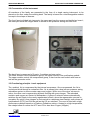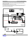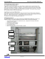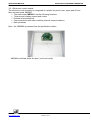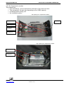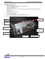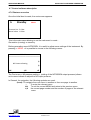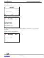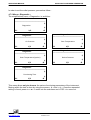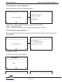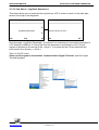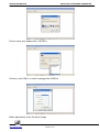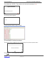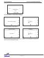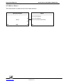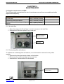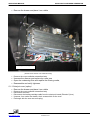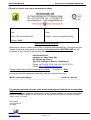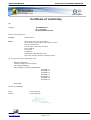
1
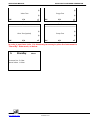
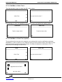
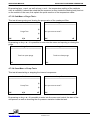
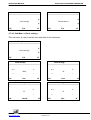
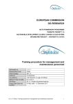
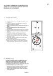
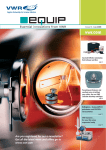
OPERATING MANUAL
HIGH PURITY NITROGEN GENERATOR
Ultra Pure Nitrogen Station
UZN2
OPERATING MANUAL
www.LNSGAS.COM
PAGE 1 of 47
OPERATING MANUAL
HIGH PURITY NITROGEN GENERATOR
TABLE OF CONTENTS
Chapter 1
INTRODUCTION
3
Chapter 2
GENERAL INFORMATIONS and COMPATIBILITY to NORMALISATIONS
2.1 Notes on the FCC compatibility
2.2 Conformity to CE regulations
2.3 W.E.E.E. product recycling declaration
2.4 Security instructions and correct use
4 to 5
4
4
4
4
Chapter 3
SPECIFICATIONS and DESCRIPTION
3.1 Specifications
3.2 Presentation of Instrument
3.3 Functioning principle : basic equipment
3.4 Functionng principle : options
3.5 Internal structures
6 to12
6
7
7
9
9
Chapter 4
INSTALLATION and OPERATION
4.1 Receipt of Instrument and check
4.2 Delivery content
4.3 Station installation
4.4 Electric connections
4.5 Fluidic connections
4.6 Initial Start-up
4.7 Control Software description
12 to 38
12
12
12
12
13
13
19
Chapter 5
MAINTENANCE
5.1 Regular maintenance of the Station
5.2 List of consumables and accessories
5.3 List of spare parts and modules
5.4 Return the instrument to the retailer or the factory
5.5 How to receive your return authorization sheet
39 to 44
39
40
41
43
43
Chapter 6
ALARMS and TROUBLESHOOTING
6.1 Troubleshooting
6.2 List of Alarms
45 to 47
45
45
NOTES
APPENDIX
46
A1 : Declaration of CE Conformity
www.LNSGAS.COM
PAGE 2 of 47
47
OPERATING MANUAL
HIGH PURITY NITROGEN GENERATOR
CHAPTER 1.
INTRODUCTION
This document provides the necessary information for the installation and operation for the
NITROGEN GENERATOR and his options; it also describes the simple maintenance
operations as well as its troubleshooting.
It is applicable to the following models of the V1 generation produced since September 2009:
•
•
•
•
UZN2-500
UZN2-750
UZN2-1300
UZN2-4000
The operating manual consider and describe an instrument generally equipped with the most
complex configuration ; should the explanation concerning the most complex instrument be
too different from the simpler instrument, both cases will be described separately.
www.LNSGAS.COM
PAGE 3 of 47
OPERATING MANUAL
HIGH PURITY NITROGEN GENERATOR
CHAPTER 2.
GENERAL INFORMATION and
COMPATIBILITY TO NORMALISATIONS
2.1 Notes on the FCC compatibility
This equipment has been tested and found compatible within the Class B limits of the digital
instruments, chapter 15 of the FCC regulation. These limits have been defined in order to
provide a reasonable protection against the strong electrical interferences in the installations
inside a residential area. This instrument generate, use and can send out some radio
frequency if it’s installed without following the manufacturer instructions; moreover it can
generate in the case of certain installations some interferences to the electrical radio
communication.
Should this instrument produce some significant interference to the radio and television, this
case can be identified by plugging and unplugging the instrument. We recommend, in order
to eliminate the interferences, to take one or more of the following actions:
Re-orientate or redirect the antenna
•
•
•
Increase the distance between the equipment and the receiver
Plug the equipment in a different electric circuit from the one alimenting the receiver
If none of the above mentioned actions are giving results, contact an experienced
technician or selling agent in radio/TV..
2.2 CE Conformity
This equipment was built in compliance and is compatible with EC recommendations
concerning electrical safety and electromagnetic emissions. It complies with 89/336/EWG,
93/98/EWG, standards EN 50 081-1, in 50 081-2, EN 50 082 - 1 and EN 50 082 - 2.
Note
Any modifications on the instrument which have not been approved in writing by the
manufacturer will automatically cancel the manufacturer warranty. If such modifications are
nevertheless undertaken, they are under the user responsibility; the manufacturer will under
no circumstances be responsible for any damages direct or indirect which they would cause
2.3 W.E.E.E. product Recycling declaration
In agreement with the European EC/2002/96 directive on electrical and electronic equipment
recycling, this product may not be disposed of in the garbage. For recycling information,
contact the company who sold this product. If you want to get rid of this instrument, identify it
as such and direct it to a certified recycling centre.
www.LNSGAS.COM
PAGE 4 of 47
OPERATING MANUAL
HIGH PURITY NITROGEN GENERATOR
2.4 Security Instructions and correct use
This Hydrogen generator has been designed in order to produce Hydrogen for laboratories’
applications. This instrument must only be used for such applications respecting the
specifications and recommendations for its proper use described in this operating manual.
The main recommendations are:
• Instrument can only be use indoors.
• It can only be use at temperatures above 4°C in a well ventilated room.
• In case of maintenance inside the instrument, always unplug it before opening the
casing.
• Only the spare parts described in chapter 5 can be changed by the user. Other
maintenances action on this instrument must be undertaken by trained and authorized
technician
www.LNSGAS.COM
PAGE 5 of 47
OPERATING MANUAL
HIGH PURITY NITROGEN GENERATOR
CHAPTER 3.
SPECIFICATIONS and DESCRIPTION
3.1 Specifications
Ultra Pure Nitrogen Station
values at 20°C and 1013 mbar of
atmospheric pressure) (
Outlet pressure
UZN2-500: 0.5 Nl/min maximum
UZN2-750: 0.75 Nl/min maximum
UZN2-1300: 1.3 Nl/min maximum
UZN2-4000: 4.0 Nl/min maximum
5 bar relative maximum
UZN2-500: 99.999%
UZN2-750: 99.999%
UZN2-1300: 99.99%
UZN2-4000: 98%
Ultra Pure Nitrogen Station purity
< 0.1ppm total Hydrocarbons, < 0.05ppm CO (only if
catalytic oven option is installed)
•
•
Purification technologies
Catalysis on high temperature Pt+Pd (option)
PSA
Particule filtration level
0.1 µm
Display
Monochrome LCD graphic display, resolution 128 x 64 pixels
Keyboard
Contextual, touch sensitive
Manual interface control
Remote control
Supply voltage
Adjust operating points, system status
Functioning diagnosis, users settings,
keyboard and screen adjustment.
Through USB interface: alarms standard reading
Remote control software on option
Through dry rely ; 1 entry (Start/Stop) and 1 alarm
100 V/60Hz; 110-117V/50-60Hz; 220- 240V / 50-60 Hz
Maximum electric consumption
550W maximum
Pressure display accuracy
0.1 bar (± 0.5 %)
Outlet fitting
Functioning conditions :
- Temperature
- Relative Humidity
Transport and storage conditions :
- Temperature
- Relative Humidity
Category of surge
Stainless steel double ring
Grade of pollution
2
Sound pressure
<50 to 55 dB(A), according to model
Net weight :
70 Kg
Dimentions : all models
360 x 640 x 695 mm (LxPxH)
Packaging size
450 x 800 x 800 mm (LxPxH)
www.LNSGAS.COM
+10°C to +35°C
0-80%, non condensing
+0°C to +35°C
0-90%, non condensing
II
PAGE 6 of 47
¼”
OPERATING MANUAL
HIGH PURITY NITROGEN GENERATOR
3.2 Presentation of the Instrument
All members of the family are presented in the form of a single casing instrument, to be
placed on the floor under the working desk. The family is based on a interchangeable module
concept in the shape of drawers.
The front face is divided into two parts, the upper part has the screen and tactile key board ;
the lower part fitted with hinges allow to accede to the pressure setting and inlet filter.
The back face is composed of 3 parts, 2 modules and one cache:
The lower module is the compression group, the upper module is the purification module.
The upper module control the compression group, it also has the main switch with fuse as
well as the generator outlet.
3.3 Functioning principle : basic equipment
The ambient Air is compressed by the internal compressor. Once compressed, the Air is
cooled and dried through a coalescent filter. Air is passed into a dual column pressure swing
adsorbtion system to remove water vapor and oxygen. While one of the dryer columns is
active, the other one is regenerating by back flushing with pure nitrogen. The adsorbed
moisture and oxygen are vented to atmosphere. A group of solenoid valves automatically
switches the air supply to the newly regenerated column, when the regeneration process is
complete. By option, pure nitrogen is next carried to a stainless steel catalytic oven where all
hydrocarbons (HTC) and CH4 as well as the CO are oxidized. The oven is fitted with a high
performance catalyst based on a Platinum-Palladium mixture. Heated to a high temperature,
the catalyst allow to reduce the HTC and CO to less than 0.1ppm (100ppb).
www.LNSGAS.COM
PAGE 7 of 47
OPERATING MANUAL
HIGH PURITY NITROGEN GENERATOR
The pressurized nitrogen is send to a tank, the capacity of which depends on the UZN2
capacity. The N2 is pressure regulated and go through a fine filter which holds 99.99 % of
particles larger than 0.5µm.
At this point the Nitrogen is available at the outlet fitting.
The compressor is driven by the tank pressure ; it will stop itself when the upper set pressure
value is reached and start again when the lower set pressure is reached; the lower tank
pressure is above the outlet set pressure.
AIR
COMPRESSION
MODULE
Low noise fans
Cooler
AIR Compressor
AIR Compressor
Filter
(external)
Relief valve
Bloc of valves
Purification columns (2X)
Coalescing
filter with
purge
Evaporator
Catalysis Oven
Low noise fan
Ventilation
DRYING and
PURIFICATION
MODULE
Tank
(Volume
depends on flow
rate capacity)
www.LNSGAS.COM
Pressure
sensor (tank)
Manual
Pressure
regulator
PAGE 8 of 47
Pressure
sensor
(Outlet)
OPERATING MANUAL
HIGH PURITY NITROGEN GENERATOR
3.4 Functioning principle: options
3.4.1 Remote control by dry relay
The option remote control by dry relay can perform a simple remote control between the
UZN2 and a external compatible « controller ». This remote control enable the start up and
shut down of the Station through a voltage between 2 terminals of the connector. The UZN2
responds by closing or opening a relay in the event of an alarm. The remote control can be
NC (normally closed) or NO (normally open).
3.4.2 Remote control via USB interface
USB remote control option allows you to read and monitor the operation of the instrument
from a PC. The delivery of the option is a software owner running under Windows (Windows
2000, XP, VISTA and Windows7) , a USB cable and operating manual.
The details of this option are described under 4.10
3.5 Internal structures
The NITROGEN station, as the other instruments of NEW TECH LINE family, is built on a
modular concept, it is mainly composed of a control module and service module(s)
• a tropicalized and light grey coated steel case , composed of a frame with sheet –
metal protection panels.
• an electronic control module
• an Air compression module
• a purification module
• tanks and linking tubes with the filtration module
Frame
Electronic
control module
Tank
N2 drying and
purification
module
Air
compression
module
www.LNSGAS.COM
PAGE 9 of 47
OPERATING MANUAL
HIGH PURITY NITROGEN GENERATOR
3.5.1 Electronic control module
The electronic control module is composed of a plastic fire proof cover, upper part of front
face and one board, MB3800
• The main board MB3800 has the following functions
• Touch screen display support and control
• External communications
• Communications with other modules (internal communications)
• Main processor
Note : the MB3800 is powered from the purification module.
MB3800 card fixed inside the lead ( vue from inside)
www.LNSGAS.COM
PAGE 10 of 47
OPERATING MANUAL
HIGH PURITY NITROGEN GENERATOR
3.5.2 Air Compression module
This module has:
• One Inlet filter(s), can be reached from the back of the lower front face
• The compressor, the type vary depending on the UZN2 capacity,
• A stainless steel cooling coil
• the ventilation system
low capacity Air compression module
Ventilation
system
Inlet filter
AIR Compressor
Command
connector
Cooling coil
high capacity Air compression module
AIR Compressor
Cooling coil
www.LNSGAS.COM
PAGE 11 of 47
OPERATING MANUAL
HIGH PURITY NITROGEN GENERATOR
3.5.3 Air purification module
This module is composed of :
• The coalescing filter with automatic purge (Purge V5)
• The bloc of solenoid valves
• The columns for PSA
• The catalytic oven with cooling coil and forced ventilation. (OPTION) Evaporator fixed
on top
• The outlet block
• The electronic control board
• The power supply board
• The pressure regulator with 2 sensors fitted on a board
This image represents the module without the ventilation tunnel.
Columns for PSA
Evaporator
Catalytic oven
with cooling coil
(option)
Connection fittings
with tank(s)
Gous3-UZN2 with
power supply
PS3550-50
N2 Outlet module
Coalescing filter
(purge V4)
www.LNSGAS.COM
Coalescing filter
Purge V5
PAGE 12 of 47
Bloc of solenoid valves
OPERATING MANUAL
HIGH PURITY NITROGEN GENERATOR
CHAPTER 4.
INSTALLATION and OPERATION
4.1 Receipt of Instrument and check
Each instrument is inspected and packaged prior to transport with great attention.
Immediately after receipt, we recommend to perform a quick visual inspection of the package
as well as the LABELCHOCS shock detector. If it turned red, report it in writing to the carrier
at the time of delivery
The UZN2 is set on an individual wooden mini-palette 40x80cm, which is the basis of its
transport packaging. Its upper part is protected by shaped foams and a thick cardboard. The
thick cardboard is screwed on the palette. The UZN2 extraction from its packaging start by
unscrewing the cardboard, then cutting the straps. At this stage it is possible to verify the
visual integrity of the instrument.
Any damages must be immediately identified and photographed; It should be reported to the
carrier as well as to your local Distributor or LNISchmidlin SA.
For major damages, the UZN2 shall be returned to the manufacturer after synchronization
with the after-sales service, which can be reached by e-mail at the
[email protected] .
4.2 Delivery content
Quantity
1
Description
NITROGEN STATION (UZN2)
1
Quick starting guide (QSG)
1
Operating manual on CD
1
Verification and calibration certificate
1
Electric cable 230V, CE
1
Shipping box
4.3 Station installation
• The UZN2 must be installed on a flat surface, without vibrations, avoiding potential
shocks and excessive heat source. The UZN2 should not be in contact with other
devices on any of its walls, a sufficient distance is necessary to avoid communicating
to other instrument the small vibrations produced.
• Operate the instrument in an open and well ventilated area, in which the temperature
does not go below 0°C . The good functioning of the instrument is guaranteed for a
temperature between +10 and +35°C.
• To ensure proper ventilation, a clear space of at least 20cm is necessary at the
back of the instrument. The Air cooling admission is located on the lower front
panel and should under no circumstances be obstructed.
www.LNSGAS.COM
PAGE 13 of 47
OPERATING MANUAL
HIGH PURITY NITROGEN GENERATOR
4.4 Electric connections
Mains: Connect the UZN2 with the electrical cable provided; If it was not possible, verify that
the cable use has a sufficient section and has a ground wire ( 3X1.5 mm2 minimum). Make
sure laboratory differential circuit breaker can absorb an inrush current of at least 10A without
switching off.
Note : the UZN2 is equipped with fuses to protect the compressor on one hand, the Catalysis
oven and electronics control on the other hand. They are placed on the back of each tray.
4.5 Fluidic connections
The PURE NITROGEN is available at the N2 OUTLET placed at the back of the instrument.
This outlet is fitted with a stainless steel Swagelock fitting, it must be connected to the
consumer through a clean and free from grease stainless tube of 1/8”. The use of AFP and
TEFLON are not recommanded, because HC and other gases diffuse through their walls
and degrade the NITROGEN purity.
Make the connection to the consumer after the purge cycle described thereafter
The instrument pressure outlet is adjusted by the pressure regulator placed under the lower
panel and can be visualized permanently on the screen.
CAUTION : your UZN2 was tested for several hours at the factory and all its tubes have been
cleaned of all ambient air contaminants. After a break of several days to several weeks of
operation, Air ambient has slightly dirty the circuit of the instrument. The walls of the tubes
need again to be cleaned. A purge cycle must be performed as described in the next chapter.
4.6 Initial Start-up
CAUTION : the dialogue between the instrument and its user is initially done via the touch
screen placed on the front top Panel. Orders or submenus are obtained by pressing lightly
with a finger on the chosen area. We strongly discourage the use of objects such as pen
pointing, the sensitive side of the screen might be irretrievably degraded.
4.6.1 Start-up
Turn the instrument on with the switch placed on the back of the instrument. The
identification image appears during approximately 30 seconds the following information will
be shown, the maker, model, serial number as well as the software revision.
LNI SCHMIDLIN SA
Ultra Pure Nitrogen Station
Model : UZN2 500 EU
S/N : UZN2-100204219
Software Rev V1.3
Innovative Swiss Made Products
Note : In order to facilitate the first start-up in your laboratory, the UZN2 has been set in the
factory for an automatic start-up and produce a pressure of 5 bar.
www.LNSGAS.COM
PAGE 14 of 47
OPERATING MANUAL
HIGH PURITY NITROGEN GENERATOR
After the presentation, the main image appear
II
RUNNING
Menu
Pressure Set : 5.0 bar
Actual value : 0.2 bar
It is possible to check the filling up progression of tank by pressing on MENU then select
Diagnostic and Internal Pressure.
The image present the tank pressure, the outlet pressure, the maximum pressure (alarm),
and the functioning state of the compressor.
4.6.2 Purge Cycle
Before connecting the UZN2 and the alimentation tube to the consumer, it is necessary to
proceed to a purge of the system:
Leave the instrument continuously working between 4 to 6 hours, limiting the outflow to
about 100 NMl/min. The outflow could be limited with a restrictor or needle valve connected
on the NITROGEN output.
From this moment, it is recommended to connect the outlet tube to the consumer and
proceed to the pressure setting.
4.6.3 Outlet pressure setting
The outlet pressure is regulates by a manual regulator, its setting is made manually while
reading on the screen the pressure value:
Open the front lower panel,
Pull the security button to set it free from its security setting
Adjust the indicated pressure value requested for the installation: turn clockwise to
increase the value.
Push back the button into its security setting.
Note : The setting procedure of the outlet pressure automatically execute a rough setting (+/0.5bar) of the alarms pressure setting. A different or finer setting can be done through the
function N2 PRESSURE ADJUSTMENT.
At this stage, the instrument is working with its factory settings. In order to improve your skills
on performance, software, maintenance period, alarms and trouble shooting, we recommend
that you read the further chapters and paragraphs of this document.
www.LNSGAS.COM
PAGE 15 of 47
OPERATING MANUAL
HIGH PURITY NITROGEN GENERATOR
4.7 Control software description
4.7.0 Features overview
Once the initial boot is made, the next screen appears:
I>
Standby
Menu
Pressure Set : 5.0 bar
Actual value : 0.2 bar
This is the main menu allowing to set the instrument in mode :
Generation (running) or stand-by.
Before generating some NITROGEN, it is useful to adjust some settings of the instrument. By
pressing « MENU » it is possible to access to the following menus :
Main Menu
=========================================
↑
N2 Pressure Setting
↓
ESC
1/6
↵
The First menu « N2 pressure setting » (setting of the NITROGEN output pressure) allows
as its name indicate to adjust the N2 output pressure.
In General, for navigation, the following symbols are used:
↑and↓ To navigate from one menu to another or from one page to another
↵
To enter the relevant menu
ESC
To exit the current MENU and return to the previous menu
1/6
the current page number and the number of pages of the relevant
menu
www.LNSGAS.COM
PAGE 16 of 47
OPERATING MANUAL
HIGH PURITY NITROGEN GENERATOR
By pressing the arrow ↓ we reach the menu « Diagnostics »,
Which allows to observe all important functioning settings of the station
Main Menu
=========================================
↑
Diagnostics
↓
ESC
2/6
Other menus are :
↵
Tools :
Providing access to various tests including the compressor test
Main Menu
=========================================
↑
Tools
↓
ESC
3/6
↵
Auxilary functions :
Allows managing the screen and clock as well as setting the working units.
Main Menu
=========================================
↑
Auxiliary Functions
↓
ESC
4/6
↵
Special functions :
Which allow to set the restart mode in case of power cut as well as the remote control and
the mode alarms.
Main Menu
=========================================
↑
Special Functions
↓
ESC
www.LNSGAS.COM
5/6
↵
PAGE 17 of 47
OPERATING MANUAL
HIGH PURITY NITROGEN GENERATOR
Alarms and events :
Allows to observe the past events.
Main Menu
=========================================
↑
Alarm + Events
↓
ESC
6/6
↵
Start up of the NITROGEN generation :
I>
Standby
Menu
Pressure Set : 5.0 bar
Actual value : 0.2 bar
Oven Temperature : 20 °C
Once the pressure has been selected (see next chapter), just press on « I> » to start the
generation.
Then the following window appears:
II
Running
Menu
Pressure Set : 5.0 bar
Actual value : 0.2 bar
www.LNSGAS.COM
PAGE 18 of 47
OPERATING MANUAL
HIGH PURITY NITROGEN GENERATOR
To stop the generation press « I I » the instrument goes automatically on « Stand by ».
In case of alarm, the message « ALARM » appears alternating with the message "Running"
or "standby".
II
Running
Menu
Pressure Set : 5.0 bar
Actual value : 0.5 bar
II
Alarm
Pressure Set : 5.0 bar
Actual value : 0.8 bar
By pressing on « Alarm » the window with the list of alarms appears:
Alarm
=========================================
Alarm 1
Alarm 2
…
…
…
ESC
In general the main page indicate
• The state of the instrumet: Stand-by, Running, alarm
• The set pressure
o The actual pressure
I>
Standby
Menu
Pressure Set : 5.0 bar
Actual value : 1.5 bar
www.LNSGAS.COM
PAGE 19 of 47
Menu
OPERATING MANUAL
HIGH PURITY NITROGEN GENERATOR
In addition, the main page allows you to:
o To start or stop the generation
o To have access to the sub menu
o To see the alarms.
Shortcut :
The center of the screen below is an active area to directly reach the pressure adjustment
window.
Pressure Set : 5.0 bar
Actual value : 0.2 bar
4.7.1 Menu « N2 pressure setting »
The tree menu « N2 pressure setting » is as follow:
Main Menu
=========================================
↑
Air Pressure Setting
↓
ESC
↵
1/6
N2 Pressure Setting
=========================================
4.8 bar
IIIIIIIIIIIIIIIIIII
Touch ↵ to memorize
ESC
↵
1/1
N2 Pressure Setting
N2 Pressure Setting
=========================================
=========================================
Maximum value : 6 bar
Actual value : 3.5 bar
New Value : 4.8 bar
ESC
www.LNSGAS.COM
Value recorded
↵
PAGE 20 of 47
OPERATING MANUAL
HIGH PURITY NITROGEN GENERATOR
In order to set the outlet pressure, proceed as follow :
4.7.2 Menu « Diagnostic »
The simplified tree menu « Diagnostic » is as follow :
Main Menu
=========================================
↑
Diagnostics
↓
ESC
2/6
↵
Diagnostics
Diagnostics
=========================================
=========================================
↑
↑
Case Temperature
Air Pressure
↓
↓
ESC
1/5
↵
ESC
4/5
↵
Diagnostics
Diagnostics
=========================================
=========================================
↑
↑
Device Features
Oven Temperature (option)
↓
↓
ESC
2/5
↵
ESC
5/5
Diagnostics
=========================================
↑
Functioning Time
↓
ESC
3/5
↵
This menu allows only to observe the various functioning parameters of the instrument.
Moving within the tree is done by using the arrows « ↑ » and « ↓ ». Once the requested
setting is found, press on « ↵ » to enter into the sub-menu and « ESC » to come out.
www.LNSGAS.COM
PAGE 21 of 47
↵
OPERATING MANUAL
HIGH PURITY NITROGEN GENERATOR
4.7.2.1 Sub-menu « N2 pressure »
This pressure is the outlet generator pressure, which will be applied on to the installation
Diagnostics
N2 Pressure Setting
=========================================
=========================================
↑
Act Value : 4.5 bar
Tank Value : 6.2 bar
↓
Max : 6.0 bar Min : 0.5 bar
IIIIIIIIIIIIIIIIIIIIIII 75%
N2 Pressure
ADC : 3125 mV Tank : 3824mV
ESC
1/5
↵
ESC
« Set Value »represent the requested pressure value
« Act Value »represent the outlet pressure measured by the sensor
« Tank Value » represent the pressure value inside the tank
« Max » and « Min » are the maximum and minimum pressure values.
The sign « IIIIIIIIIIIIIIIIIII 98% » indicate at which % max of the pressure the setting is.
« ADC » indicate the value of the pressure analogous digital converter.
4.7.2.2 Sub-menu « Oven Temperature » (option)
This value indicates the catalysis oven temperature
Diagnostics
Oven Temperature
=========================================
=========================================
↑
Actual Value : 645 °C
Oven Temperature
Max Value : 660 °C
↓
ESC
2/5
ADC :
↵
2825 mV
ESC
4.7.2.3 Sub-menu « Functioning Time »
This value indicate the functioning time of the instrument as well as the next maintenance.
Diagnostics
Functioning Time
=========================================
=========================================
Actual Value : 12 Hours
↑
Functioning Time
↓
ESC
3/5
↵
Next Maint. : 4000 Hours
Remaining Time : 3988 hours
IIIIIIIIIIIIIIIIIIIIIII 99%
ESC
« Actual Value » functioning time since beginning of the instrument life
www.LNSGAS.COM
PAGE 22 of 47
OPERATING MANUAL
HIGH PURITY NITROGEN GENERATOR
« Next Maint. »is the functioning time corresponding to the next maintenance .
« Remaining Time » remaining time before the next maintenance.
The sign « IIIIIIIIIIIIIIIIIII 99% » indicates the functioning « reserve » before maintenance
Once the « remaining time » reaches zero, an indication « Alarm » appears on the
screen main menu :
I>
Alarm
Menu
Pressure Set : 5.0 bar
Actual value : 4.9 bar
When the maintenance is done, go back to the menu « Diagnostic »\ « Total functioning
time » and press on « Maintenance done »
Total Functioning Time
=========================================
Actual Value : 8 Hours
Next Maintenance : 4000 Hours
Remaining Time : 3992 Hours
IIIIIIIIIIIIIIIIIIIIIII 98%
Maintenance Done
ESC
At this time « maintenance done » disappear, the messages « Next maintenance » is
incremented by 4000H and the message « Remaining time » is up dated.
Moreover, the message « Alarm » on the main menu disappear.
www.LNSGAS.COM
PAGE 23 of 47
OPERATING MANUAL
HIGH PURITY NITROGEN GENERATOR
4.7.2.4 Sub-menu « Case Temperature »
This value tells about electronic case temperature.
Diagnostics
Case Temperature
=========================================
=========================================
Case Temp. : 26°C (79°F)
↑
Alarm :57°C (135°F)
↓
ADC : 432
Voltage :263 mV
Case Temperature
ESC
4/5
↵
ESC
« Case Temp.» represents the temperature of the electronic module
« Alarm » is the Alarm value.
« ADC » represents the value of the analogue to digital voltage converter
4.7.2.5 Sub-menu « Device Features »
This sub menu allows to view the instrument model, the serial number as well as the version
of the software.
.
Diagnostics
Device Features
=========================================
=========================================
Mod : UZN2 3L-EU
↑
Device Features
S/N : UZN21-091004099
Software Revision : V1.1
↓
ESC
5/5
↵
ESC
4.7.3 Menu « Tools »
The tree of this menu is the following ::
Main Menu
=========================================
↑
Tools
ESC
3/6
↵
Tools
Tools
=========================================
=========================================
www.LNSGAS.COM
PAGE 24 of 47
OPERATING MANUAL
HIGH PURITY NITROGEN GENERATOR
↑
↑
Valve Test
Purge Test
↓
ESC
↵
1/4
↓
ESC
3/4
↵
Tools
Tools
=========================================
=========================================
↑
↑
Oven Test (option)
Pump Test
↓
ESC
↵
2/4
↓
ESC
4/4
↵
In order to use these tools, it is absolutely necessary to place the instrument in
"Stand-By" State mode, as below.
I>
Standby
Menu
Pressure Set : 5.0 bar
Actual value : 0.2 bar
www.LNSGAS.COM
PAGE 25 of 47
OPERATING MANUAL
HIGH PURITY NITROGEN GENERATOR
4.7.3.1 Sub-Menu « Valve Test »
This test allows to open or close the N2 outlet valves.
Tools
=========================================
Valve Test
=========================================
↑
Valve Test
Are you sure to enter ?
↓
ESC
1/4
↵
↵
ESC
By pressing on « ↵ » It is possible to go into the menu and adjust the setting value
Valve Test
Valve Test
=========================================
=========================================
Touch to open valve
Touch to close valve
ESC
ESC
4.7.3.2 Sub-Menu « Oven Test »(option)
This test allows direct access to the catalysis oven setting which can be modified as requested.
WARNING: in order to allow for a very different setting to factory default setting, this feature is little
protected against excessive adjustment values. A constant temperature setting above 750 ° C
temperature can damage the instrument.
Tools
Oven Test
=========================================
=========================================
↑
Oven Test
Are you sure to enter ?
↓
ESC
2/4
↵
ESC
Oven Test
=========================================
++
+
Regulate oven to 700°C
-Act temp. 285°C
ESC
www.LNSGAS.COM
↵
PAGE 26 of 47
↵
OPERATING MANUAL
HIGH PURITY NITROGEN GENERATOR
By pressing keys ++and –as well as keys + and -, the temperature setting of the catalysis
oven is modified. It should be noted that the measure is done inside the heating body and not
on the outskirt of the oven; this explain the quick reaction of the temperature value.
4.7.3.3 Sub-Menu « Purge Test »
This test allows opening and closing the purge valve of the coalescent filter.
Tools
Purge Test
=========================================
=========================================
↑
Purge Test
Are you sure to enter?
↓
ESC
3/4
↵
↵
ESC
By pressing on key « ↵ » it is possible to enter into the menu and opening or closing the
purge.
Purge Test
Purge Test
=========================================
=========================================
Touch to open purge
Touch to close purge
ESC
ESC
4.7.3.4 Sous-Menu « Pump Test »
This test allows starting or stopping the internal compressor
Tools
Pump Test
=========================================
=========================================
↑
Pump Test
Are you sure to enter?
↓
ESC
4/4
↵
ESC
↵
By pressing on key « ↵ » It’s possible to enter into the menu and control the start of the
compressor as well as checking the Air pressure variation inside the tank.
www.LNSGAS.COM
PAGE 27 of 47
OPERATING MANUAL
HIGH PURITY NITROGEN GENERATOR
Pump Test
=========================================
Tank pressure value : 3.5 bar
Touch to Stop Pump
IIIIIIIIIIIIIIIIIIIII 72%
ESC
4.7.4 Menu « Auxiliary functions »
This menu tree is the following :
Main Menu
=========================================
↑
Auxiliary Functions
↓
ESC
5/6
↵
Auxiliary Functions
Auxiliary Functions
=========================================
=========================================
↑
↑
Clock Settings
Alarm setting
↓
ESC
1/6
↵
↓
ESC
Auxiliary Functions
4/6
↵
Auxiliary Functions
=========================================
=========================================
↑
↑
Display Settings
Touch Pad Calibration
↓
ESC
www.LNSGAS.COM
2/6
↵
↓
ESC
PAGE 28 of 47
5/6
↵
OPERATING MANUAL
HIGH PURITY NITROGEN GENERATOR
Auxiliary Functions
Auxiliary Functions
=========================================
=========================================
↑
↑
Unit Change
Sounds Menu
↓
ESC
↵
3/6
↓
ESC
↵
6/6
4.7.4.1 Sub-Menu « Clock setting »
This sub menu is used to set the time and date of the instrument
Auxiliary Functions
=========================================
↑
Clock Settings
↓
ESC
↵
1/6
Clock Settings
Clock Settings
=========================================
++
=========================================
+
++
2009
- -
10
-
ESC
- -
↵
Year
ESC
Clock Settings
+
++
+
27
-
www.LNSGAS.COM
↵
=========================================
12
Month
Hour
Clock Settings
=========================================
ESC
+
- -
↵
ESC
PAGE 29 of 47
Min
↵
OPERATING MANUAL
HIGH PURITY NITROGEN GENERATOR
Clock Settings
Clock Settings
=========================================
++
=========================================
17/12/2009
10 :27
+
17
- -
-
ESC
Day
↵
Once entered in the menu « Clock setting », the software requires in turn the year (Year), the
month (Month),the day (Day), the time (hour) and the minute (Min). Once in the menu, the
« + » and the « ++ » allows to increase the value, the « - » and the « - - » allows to decrease
the value. The « ++ » and « - - » allow a rapid scroll of the values, the « + » and « - » allows a
slow scroll of values.
The entered value is validated by pressing « ↵ ». The software automatically advances to the
next value.
Once all the values are entered the last "page" displays the date and time set.
4.7.4.2 Sub- Menu « Display Setting »
Auxiliary Functions
Display Settings
=========================================
=========================================
↑
++
Display Settings
IIIIIIIIIIIIIIIIIIIIIII
↓
ESC
2/6
+
↵
- ESC
-
↵
Contrast
Display Settings
=========================================
++
+
IIIIIIIIIIIIIIIIIIIIIII
- ESC
Backlight
↵
This sub menu allows to set the contrast (Contrast) as well as the reverse light screen (light
back). Proceed adjustments with buttons « + », « ++ » and « - » and « - - »
The value entered is validated be pressing on « ↵ ». The software automatically advances to
the next value.
www.LNSGAS.COM
PAGE 30 of 47
OPERATING MANUAL
HIGH PURITY NITROGEN GENERATOR
4.7.4.3 Sub- Menu « Unit Change »
This menu allows choosing the working units
Auxiliary Functions
=========================================
↑
Unit Change
↓
ESC
↵
3/6
Units
Pressure
Pressure
Pressure
=====================
=====================
=====================
=====================
↑
↑
↑
↑
Pressure
Bar
↓
ESC
1/ 2
↵
Kpa
↓
ESC
1/ 3
↵
Psi
↓
ESC
2/ 3
↵
Units
Temperature
Temperature
=====================
=====================
=====================
↑
↑
↑
Temperature
°C
↓
ESC
2/ 2
↵
1/ 2
ESC
3/ 3
°F
↓
ESC
↓
↵
↓
ESC
2/2
↵
Once in the « UNIT » menu it is possible with the keys « ↑ » and « ↓ » to change the
following units : Pressure and Temperature.
Once in the requested window (Pressure or Temperature) press on « ↵ » and choose with
the arrows « ↑ » and « ↓ » then validate with « ↵ » the requested unit.
For the pressure, the units are: Bar, Kilo Pascal and PSI
For the temperature the units are: Degree Celsius and Fahrenheit
www.LNSGAS.COM
PAGE 31 of 47
↵
OPERATING MANUAL
HIGH PURITY NITROGEN GENERATOR
4.7.4.4 Sub- Menu « Alarm Setting»
Auxiliary Functions
Alarm functions
=========================================
=========================================
↑
↑
Alarm functions
Buzzer ON
↓
ESC
4/6
↓
↵
↵
ESC
Value recorded
This sub menu allows enabling or disabling the sound signal in case of alarm (Buzzer).
Once in the menu, choose between “ON” or “OFF” with the arrows then valid with
« ↵ ».
4.7.4.5 Sub- Menu « Touch pad Calibration »
This sub menu allows calibrating the touch screen.
Auxiliary Functions
Calibration
=========================================
Touch black square
↑
Touch Pad Calibration
Remove finger
↓
ESC
5/6
↵
Touch black square
Touch the pad
X:0 Y:0 0
Calibration
www.LNSGAS.COM
PAGE 32 of 47
OPERATING MANUAL
HIGH PURITY NITROGEN GENERATOR
Calibration
Touch black square
Touch black square
X:0 Y:0 0
Remove finger
Calibration
Once in the sub menu « touch pad setting » the software ask to press on the screen (Touch
the pad). After having press on the screen, the software ask to press on the square placed on
the top left hand corner and to keep the finger on it (touch black square). At that time a
counter starts up. Once arrived at the value 10, the next page ask to remove the finger
(remove finger) appears. Then another calibration point is requested (bottom right hand
corner). When done, the message « calibration done » (Pad Calibration done) appears.
Pad Calibration done
4.7.4.6 Sub- Menu « Sounds Menu»
Auxiliary Functions
Sounds Menu
=========================================
=========================================
↑
↑
Sounds Menu
IIIIIIIIIIIIIIIIIIIIIII
50 %
↓
ESC
6/6
↵
ESC
↓
↵
This sub menu lets you adjust the duration of the sound emitted when the screen is touched. A setting
to 0 % totally removes the sound.
www.LNSGAS.COM
PAGE 33 of 47
OPERATING MANUAL
HIGH PURITY NITROGEN GENERATOR
4.7.5 Menu « Special functions »
This menu tree is the following :
Main Menu
=========================================
↑
Special Functions
↓
ESC
5/6
↵
Special Functions
Special Functions
=========================================
=========================================
↑
↑
Power Up Control
Pressure Level Alarm
↓
ESC
1/6
↵
↓
ESC
4/6
↵
Special Functions
Special Functions
=========================================
=========================================
↑
↑
Remote Control
Service Alarm Settings
↓
ESC
2/6
↵
↓
ESC
5/6
↵
Special Functions
Special Functions
=========================================
=========================================
↑
↑
Log Book download
Pass Word
↓
ESC
www.LNSGAS.COM
3/6
↵
↓
ESC
PAGE 34 of 47
6/6
↵
OPERATING MANUAL
HIGH PURITY NITROGEN GENERATOR
4.7.5.1 Sub- Menu « Power Up Control »
This menu is used to determine, in the event of power failure, in which state the instrument
must restart. There are two possibilities:
Restart in the same Status it was before the power failure (On Last Running Status)
Restart and go in « stand-By » Status (On Standby Status)
Special Functions
Power Up Control
=========================================
=========================================
↑
↑
Power Up Control
On Standby Status
↓
ESC
1/6
↵
↓
ESC
1/2
↵
Power Up Control
=========================================
↑
On Last Running Status
↓
ESC
4.7.5.2 Sub- Menu « Remote Control »
Special Functions
=========================================
↑
Remote Control
↓
ESC
www.LNSGAS.COM
2/6
↵
PAGE 35 of 47
2/2
↵
OPERATING MANUAL
HIGH PURITY NITROGEN GENERATOR
4.7.5.3 Sub- Menu « Log Book Download »
This menu allows you to download the log book on a PC in order to send it to the after sale
service for a help in the diagnosis.
Special Functions
Log Book Download
=========================================
=========================================
↑
Log Book Download
Please Connect to a PC
↓
ESC
3/6
↵
ESC
↵
Once the page « log Book Download » is reached, it is necessary to connect the generator to
a PC through a USB link. If it’s the first time the generator is connected to a PC, he will
request to proceed to the set up of the « driver ». It is stored on the CD provided with the
instrument in the directory « driver »
Then, on the PC menu
\Start up \all programs \accessories \communication \Hyper Terminal open the Hyper
Terminal program
www.LNSGAS.COM
PAGE 36 of 47
OPERATING MANUAL
HIGH PURITY NITROGEN GENERATOR
Enter a name and validate with « ENTER »
Choose « port COM » on which is plugged the USB link
Make adjustments as on the above image
www.LNSGAS.COM
PAGE 37 of 47
OPERATING MANUAL
HIGH PURITY NITROGEN GENERATOR
Then validate with « ENTER ». Then validate on the instrument by pressing on « ↵ «.
Log Book Download
=========================================
Please Connect to a PC
↵
ESC
The following window appears
OK
Log book appears (coded) in Hyper Terminal.
4.7.5.4 Sub- Menu « Pressure Level Alarm»
This submenu allows to adjust the value corresponding to the minimum pressure alarm.
Special Functions
=========================================
↑
Pressure Level Alarm
↓
ESC
4/6
↵
By pressing on « ↵ »,the setting window appears
www.LNSGAS.COM
PAGE 38 of 47
OPERATING MANUAL
HIGH PURITY NITROGEN GENERATOR
Pressure Level Alarm
=========================================
++
+
IIIIIIIIIIIIIIIIIIIIIII
- -
-
4.2 bar
ESC
↵
Pressure Min
4.7.5.5 Sub- Menu « Service Alarm Settings »
Special Functions
PassWord
=========================================
=========================================
↑
↑
Service Alarm Settings
000000
↓
ESC
5/6
↵
↓
ESC
↵
4.7.5.6 Sub- Menu « Pass Word »
Special Functions
PassWord
=========================================
=========================================
↑
↑
Pass Word
000000
↓
ESC
6/6
↵
↓
ESC
↵
This sub menu allows access to the function « USINE » is not accessible to persons who
have not received adequate training.
www.LNSGAS.COM
PAGE 39 of 47
OPERATING MANUAL
HIGH PURITY NITROGEN GENERATOR
4.7.6 Menu « Alarm »
This menu allows to check the list of the latest alarmes :
Special Functions
Alarm
=========================================
=========================================
↑
Alarm
↓
ESC
www.LNSGAS.COM
6/6
↵
15.12 10 :56 Reset
10.12 13 :34 Reset
28.11 07 :03 Pressure failed
…
…
ESC
PAGE 40 of 47
OPERATING MANUAL
HIGH PURITY NITROGEN GENERATOR
CHAPTER 5.
MAINTENANCE
5.1 Regular maintenance of UZN2
The following table summarizes the acts of maintenance as well as consumables probable
replacement frequency.
Maintenance
Frequence
Air inlet filter
Every 6 months (4000H)
Coalescing filter with silencer
Catalysis oven with heating cartridge
(option)
Every 6 months (4000H)
Article Number
Every 3 years (24000H)
5.1.1 Air inlet filter
• Open the lower part of front face, in order to access to the inlet filter.
• Unscrew the filter and replace it by a new one
Pressure regulator’s
adjustment button
Inlet filter
5.1.2 Coalescing filter with silencer
To replace the coalescing filter and silencer, we recommend to remove the Air purifier
module:
• Unscrew the lateral protection plates on both sides
• Disconnect the cable and tubes on the rear face
• Unscrew the 4 screws which fix the drawer
Screws to fix the module
(4x) by drawer
www.LNSGAS.COM
PAGE 41 of 47
OPERATING MANUAL
HIGH PURITY NITROGEN GENERATOR
• Remove the drawer and place it on a table
Silencer,
evaporator
Catalysis oven
Coalescing filter
Coalescing filter (Purge V5)
(drawer shown without oven streamline body)
•
Remove the oven ventilation streamline body
• Unscrew the silencer and replace by a new one
• Open the coalescing filter and replace the filtering media,
• Reassemble and verify tightness
5.1.3 Catalysis oven (option)
• Remove the drawer and place it on a table
•
•
•
•
•
Remove the oven ventilation streamline body
Disconnect the tubes
Disconnect the heating cartridge cable from the electronic board (Phoenix 5 pins)
Unscrew, from under the drawer, the 4 screws which fix the oven.
Exchange with the new one and replug.
www.LNSGAS.COM
PAGE 42 of 47
OPERATING MANUAL
HIGH PURITY NITROGEN GENERATOR
5.2 List of Consumables and accessories
The following table lists the available LNI Schmidlin SA items for light maintenance on the
NITROGEN generator (UZN2), as well as the recommended accessories::
# article LNS
6711 02 220
6711 02 224
DESCRIPTION
Air : set of filters (coalescent V4 + dust) Model Purge V4
Air : set of filters (coalescent V5 + dust) Model Purge V5
IMPORTANT!
The manufacturer reserves the right to change or modify its products without prior notice.
5.4 Return the instrument to the retailer or the factory
In the event your instrument must be returned to the factory for a repair which cannot be
carried out on the spot, please contact your agent by specifying in detail the problem as well
as the instrument operating environment, the type and the serial number.
This done, your agent will provide all the necessary instructions to return the instrument in
the best conditions.
In case where the warranty period would have expired, or in case the default would be due to
misuse of the instrument, all transport and repair costs incurred would be the sole
responsibility of the user, unless special arrangement between the manufacturer and the
client had been undertaken.
• Disconnect the Nitrogen generator from its application
• Place the instrument in its original packaging box or in another box where the
instrument cannot move
• Fixe the FRAGILE label
• Fill in and send back to your provider or to the factory the form called « Return
Autorization Sheet » presented below. This document is necessary in order to link to
the instrument all the information given to the SAV by phone, e-mail or other means.
Make sure that the instrument will never be exposed during transport or storage, to a
temperature below - 5 ° C.
www.LNSGAS.COM
PAGE 43 of 47
OPERATING MANUAL
HIGH PURITY NITROGEN GENERATOR
5.5 How to receive your return authorization sheet
To:
Fax:
Attn.:
Date:
From: Mr. Laurent Boucher
Pages: 1 (this front page included)
Subject: RA#
Return Authorisation Sheet
Referring to various e-mails, phone calls or personal talks between Mr. L.Boucher and you,
please forward all spare parts or instruments directly back to SWITZERLAND via the
forwarder of your choice to the following address:
LNI Schmidlin SA
attention to: After Sales Dpt
46, Chemin de l’Etang
CH-1219 Châtelaine, Genève, Switzerland
Phone: +41 22 979 37 24; Fax: +41 22 979 37 20
E-mail: [email protected]
Please clearly note on all the shipping documents:
Your RA no.: RA#
and clearly describe (absolutely required!) what the returned items are:
Model / part (description):
serial no. / part no.
---------------------------------------------------------------------------------------------------------------------------------------------
For customs purpose, the max. value of the shipped goods should not be more than:
EURO 400.00. Without any other agreement (which should be confirmed by written letter or e-mail through
LNI Schmidlin SA ) ALL shipment -and assurance costs, no matter if billable –or warranty case, will be
at your or customer’s charge. Please make sure that material is properly packed. For further assistance,
please contact us anytime.
Best regards,
LNI Schmidlin SA
SAV Dept
www.LNSGAS.COM
PAGE 44 of 47
OPERATING MANUAL
HIGH PURITY NITROGEN GENERATOR
CHAPTER 6.
TROUBLESHOOTING and ALARMS
6.1 Troubleshooting
The following table describes major cases of malfunctions which the user will be able to fix
without the help of trained technicians on this product. In case of more complex failures, the
modular concept of the LINEA10 line, allow to do a standard exchange of the faulty module
without having to send back the full instrument to the retailer or the factory. Refer to the
service manual.
SYMPTOM
CAUSE(S) + CORRECTION(S)
The instrument does not
start, nothing appears on the
screen.
1) Faulty or badly connected electric cable ; check
2) Fuse melted, replace by a fuse of similar value( value depend on
compressor power)
3) Power cable between PS3550 and MB3800 or between MB3800 and screen
not connected or faulty ; check
4) MB3800 board is faulty.
1) The alimentation pressure is inferior to the expected value. Verify the
alimenting line
2) The nitrogen consumption is superior to the instrument’s capacity, verify
there is some flow restrictor (the consumer) fixed at the Air Outlet.
3) The pressure sensor is out of order. Verify with a gage
It is not possible to adjust the
pressure to the expected
value.
The instrument does not
1) The alimenting pressure is inferior to the Air pressure setting
reach the expected
2) nitrogen consumption is superior to the instrument’s capacity
pressure. N2 pressure Alarm 3) The UZN2 supplies a circuit with a large dead volume, the pressure increase
but too slowly. If there is no leak on the circuit the desired pressure will be
reached. To speed up the rise, reduce the circuit volume or acquire another
generator and mount them in parallel mode.
4) There is an important leak on the circuit between UZN2 and user. Verify and
reduce leak
The instrument does not
1) The consumption is not constant and grows quickly, the instrument cannot
generate a constant
keep up; install a small extra tank as well as a pressure regulator.
pressure
2) The consumption is very close to the maximum, even go over it ;
Reduce the consumption or increase the generation capacity.
Oven temperature close to
1) The heating cartridge is not functioning properly. Verify the connector and
ambient temperature
wiring
2) The control board GOUS3 is not connected to the internal communication
bus. Verify connection and plug again the module
Oven temperature over
1) The heating cartridge is probably melted. The temperature sensor
750°C
(thermocouple K-type) inside is out of order. Verify voltage by “Diagnostics”
Menu and eventually wiring. Call SAV-LNS for help on diagnostics.
If heating cartridge is melted, the complete oven must be replaced.
www.LNSGAS.COM
PAGE 45 of 47
OPERATING MANUAL
HIGH PURITY NITROGEN GENERATOR
NOTES
www.LNSGAS.COM
PAGE 46 of 47
OPERATING MANUAL
HIGH PURITY NITROGEN GENERATOR
Certificate of conformity
We,
LNI SCHMIDLIN SA
46, ch. de l’Etang
CH-1219 Châtelaine-Genève
Company:
Declare and certify that our
Products:
GAS Generators
Brand:
H2 FID / H2 Carrier / H2-Air FID station
Compressed Air station / Mini compressed Air station
Zero Air / Ultra Zero Air
Zero Air station / Ultra zero Air station
PG-H2 / NM-H2
N-GC / N-GT
N2-SIROCCO
N2-MISTRAL LCMS / Whisper Series
High Purity Nitrogen Generator / Nitrogen Station
Are in conformity with the following CE rules :
Machines 2006/42/CE.
Equipment under pressure 97/23/CE
Low voltage 2006/95/CE
Electromagnetic compability 2004/108/CE :
EN 61000-3-3
EN 61000-4-3
EN 61000-4-4
EN 61000-4-5
EN 61000-4-6
EN 61000-4-8
EN 61000-4-11
RoHS, WEEE
Geneva, the 10.03.2011
Name:
Position:
www.LNSGAS.COM
Daniel Calabrese
Product Manager
PAGE 47 of 47