1
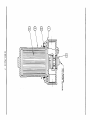
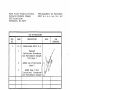
FACET FILTER MT NO. 1741350-01
INSTALLATION AND SERVICE MANUAL
SCAVENGE LUBE OIL FILTER SYSTEM FOR
EUROCOPTER (MBB) BK117A-1, A-3, A-4, B-i AND B-2
MODEL HELICOPTERS
(Update for ifiter kit no. 1741280)
CONTENTS:
INSTALLATION AND SERVICE INSTRUCTIONS
WARRANTY INFORMATION
FLIGHT MANUAL SUPPLEMENT
STC NO. SH2397S0
E-961 Rev. E
AUGUST 10, 1993
PUROLATOR FACET, INC.
8439 TRIAD DRIVE, GREENSBORO, NC 27409-9621
PHONE: (336) 668-4444
FAX: (336) 668-4452
NOTICE TO PERSONS RECEIVING THIS DOCUMENT:
PUROLATOR FACEY INC CLAIMS PROPPJETARYRIGHTSIN THE MATERIAL DISCLOSED HEREOI’i THIS DOCUMENTISISSUED iN
THE CONFIDENCE FOR ENGINEERING INFORMATION ONLYAND MAYNOTBE USED TO MANUFACTURE ANYTHING SHOWN
WITHOUT THE DIRECT WRITTEN PERMISSION FROM PUROLA TOR TO THE USER.
E-961
GENERAL INFORMATION
The purpose of the Facet Scavenge Lube Oil Filter is to clean the oil to a much finer degree
than factory equipped strainers. The filter has a 3 micron absolute element. Located in the
line from the engine to the oil cooler, the filter prevents particles from contaminating the oil
cooler and supply tank and recirculating through the engine.
The filter assembly is equipped with a relief valve that opens when the differential pressure
across the element reaches 12±1.2 PSID. The bypass indicator extends a red indicator pin
when the valve opens. The pin remains extended until manually reset. Thermal lockout
prevents indicator actuation below 110±15°F.
8-961, Rev E 2
FACET KIT NO. 1741350-01 FOR MBB BKI17A-1, A-3, A-4, B-i, B-2
WITH FACET FILTER KIT 1741280 INSTALLED
REG. NO.
SER. NO.
FLIGHT HOURS _________________________________
INSTALLATION DATE _____________________________
It is recommended that this manual be included in the permanent records of the modified
helicopter to comply with the FM requirement that the STC be retained and to have for
service reference.
At the time of installation, please fill out the warranty card and mail.
E-961, Rev E 3
PARTS LIST FOR FACET KIT NO. 1741350-01
FOR MBB HELICOPTER MODELS BK117A-1, A-3, A-4, B-i, B-2
WITH FACET FILTER KIT 1741280 INSTALLED
Oty
Item
No.
2
3
4
5
6
7
8
9
10
11
12
13
14
15
16
17
18
19
20
21
22
23
24
25
26
27
28
29
Part Number
Description
Req’d
AN4-32A
AN960-416
1741111-01
MS21 042-L4
AN924-1OJ
1741110-50
1741282
040373
034937
AN832-1OJ
1741110-51
1741352
1741353
MS21919WDG-10
MS35207-263
M521 042-L3
AN960-1OL
MS21919WDG-12
MS35207-267
1741285
1741283
1741126
1741110-52
1741110-55
E-961
MS21919WDG-14
1741175
1741350-01
1743866
Bolt
Washer
Spacer
Nut Self Locking
Nut
Hose Assembly LH
Reducer
0-ring FLBN-912
0-ring FLBN-910
Bulkhead Fitting Straight
Hose Assembly RH
Junction Assembly LH
Junction Assembly RH
Clamp
Screw
Nut Self Locking
Washer
Clamp
Screw
Extension Wire
Doubler
Spiral Wrap
Hose Assembly LH
Hose Assembly RH
Installation Manual
Clamp
Tool (not shown)
Installation Drawing
Warning Tag
-
-
-
-
-
-
-
-
RH Right-hand
LH Left-hand
-
-
E-961,RevE
4
6
12
6
6
2
1
4
4
8
2
1
1
1
8
4
8
4
2
4
2
2
24”
1
1
1
2
1
1
1
IMPORTANT INFORMATION FOR FACET KIT NO. 1741 350-01
Preflight Inspection Procedure Change:
Scavenge line oil filter check red indicator.
Scavenge Oil Filter Check:
A.
Inspect red button on head assembly for indication of filter bypass.
B.
If red button is not showing, proceed with preflight.
C.
Red button showing, reset button once and run engine.
D.
If red button reappears, discontinue operations and investigate reason for filter
bypass indication.
Red Bypass Indicator Reset:
Press and turn in.
Scavenge Oil Filter Service:
A.
Replace element whenever the engine oil is changed.
B.
When filter is serviced after bypass indication, a new filter element and 0-ring
should be installed.
Scavenge Oil Filter Assembly Functional Check:
At installation and every subsequent 1000 hours, using Facet Tool P/N 1741175,
functionally check filter assembly bypass indicator.
A.
Remove safety wire, unscrew bowl, remove and discard installed filter element.
B.
Install Tool P/N 1741175, reinstall bowl, do not safety at this time, leave cowling
locked open or removed for visual access to filter assembly.
C.
Start engine, operate at ground idle until normal operating temperatures are
reached, and filter bypass indicator button extends (approximately 10 minutes).
Indicator must reach 110±15°F to operate.
D.
Secure engine, remove bowl and tool, install new seal kit and filter element,
reinstall and safety bowl, reset indicator, drain and reservice engine oil system.
CAUTION: ENSURE TOOL IS REMOVED PRIOR TO FLIGHT.
E-961, Rev E 5
E.
If bypass indicator fails to extend, or will not reset, contact Facet Filter Products
Division, 919-668-4444.
Weight Change:
Kit 1741280
Removal Weight Change:
-8.62 lbs
Kit 1741350-01 Installation Weight Change: ÷7.9 lbs
Arm: 4485 mm
Arm: 4820 mm
REPLACEMENT PARTS FOR FACET FILTER ASSEMBLY P/N 1742500
Item
Part No.
Description
1
1742224-01
Head Assembly
2
1742439
0-ring
3
1742510
Element
4
1742241-01
Bowl
5
1742227-01-42 Valve and Indicator Assembly
NOTE:
For optional Kit Replacement Element with Bowl 0-ring and Instructions
use P/N 1742510-01.
Filter Element Change Instruction:
A.
Remove head to bowl lockwire and unscrew bowl.
B.
Remove dirty element.
C.
Remove and discard 0-ring from filter bowl.
D.
Install new element.
E.
Install new 0-ring on filter bowl.
F.
Hand tighten until tight against head and lockwire.
NOTE:
Only Facet authorized approved replacement parts may be used to maintain
warranty. Valve and indicator assemblies are factory set.
E-961, Rev E 6
Ill
CD
0)
-I.
CD
Ill
-4
WV,
C
-I
z
INSTALLATION INSTRUCTIONS FOR FACET KIT NO. 1741350-01 FOR MBB
HELICOPTER BK117A-1, A-3, A-4, B-i, B-2 WITH FACET KIT 1741280 PREVIOUSLY
INSTALLED
General:
This installation can best be accomplished at a time when the oil is drained from both
engine lubrication systems.
Both left and right engine installations will be almost the same.
The filter assembly was factory tested and shipped wet with MIL-L-7808, aircraft turbine
engine lubricating oil.
It is recommended that the installer read through the instructions completely before
starting, to ensure that there will be no problems with completing this installation.
Preparation:
1.
Disconnect battery.
2.
Remove cowling as required to work in the transmission and engine sections (both
LH and RH). Drain engine oil systems.
Note:
LH
Note:
Refer to drawing 1741280, furnished with kit 1741280, for
location of removed items.
-
Left-hand, RH
-
Right-hand
3.
Remove and discard hose clamp Item 17, 1741025, reinstall screw in transmission
oil pump cover. Remove and discard clamp assemblies (4) Item 9, 1741012 (LH
and RH).
4.
Remove and discard inlet hose Item 12, 1741110-39 (LH and RH), outlet hose
Item 23, 1741110-37 (RH) and Item 8,1741110-35 (LH). Disconnectthermal valve
inlet hose (117-67060-03) at tee fitting Item 16, AN824-1OD, remove and discard
tee and tube assembly Item 5, 1741016. Remove and discard tiewrap Item 19,
1741013, drain tube Item 18, 1741009 and clamp assembly Item 15, 1741021 (LH
and RH).
E-961,RevE 8
5.
Remove drainpan attaching hardware, remove drainpan and filter assembly,
reinstall attaching hardware. Remove filter assembly from drainpan Item 6,
1741017 (RH), Item 7, 1741018 (LH). Discard drain pan and fHter assembly attach
hardware. Remove and discard union Item 12, AN913-20D at filter assembly inlet
and outlet ports. Retain filter assembly for reinstallation (LH and RH).
Note:
Replacement filter element (not furnished) may be installed at this
time.
6.
Locate and gain access to debris monitor, remove chip detector plug. Remove two bolts
securing debris monitor bracket to firewall. Disconnect vent hose at forward side of
firewall, remove jam nut and washer. Remove screw for transducer adel clamp from
firewall (if installed). Retain all hardware for reinstallation (LH and RH).
7.
On engine side of firewall, locate and disconnect engine oil hose at debris monitor
bulkhead fitting. Remove jam nut on bulkhead fitting, remove debris monitor from
firewall, retain all attaching hardware (LH and RH).
8.
Remove 900 elbow fitting Item 11, AN833-1 OD, from debris monitor outlet, retain
fitting and jam nuts; discard bracket. Remove 900 bulkhead fitting and union from
debris monitor inlet, discard fitting, retain union for reinstallation (LH and RH).
Note:
Discard drawing 1741280. See new drawing 1741350-01.
9.
Temporarily install doubler Item 21, 1741283 at debris monitor bracket mounting
nutplates with previously removed screws and washers and at debris monitor
bulkhead fitting hole with bulkhead fitting and nut, Items 10 and 5.
10.
Mark filter assembly mounting holes and transducer mount hole if not drilled. Remove
doubler. Drill and deburr filter assembly mounting holes (.266 dia. inches) and
transducer mount hole (.213 dia. inches). Reinstall doubler with bracket mounting
screws and washers. Attach transducer screw, or screw Item 15, MS35207-263, nut
Item 16, MS21042-L3, and washer Item 17, AN960-1OL (LH and RH).
CAUTION:
Make sure all cables and lines are clear before drilling.
11.
Install 0-ring Item 9, 034937 on the adapter end of bulkhead fitting Item 10,
AN832-1OJ, and install securely into the inlet end of the debris monitor (LH and
RH).
12.
Install 0-ring, Item 9, 034937, on end of previously removed union AN815-1OD and
install in outlet end of debris monitor. Set debris monitor aside temporarily. (LH
and RH).
E-961, Rev E 9
13.
Place 0-rings Item 8, 040373, on reducers Item 7, 1741282, and install securely
into the inlet and outlet of filter assembly 1742500. Place lam nut (previously
removed) and 0-ring Item 9, 034937, on on bulkhead end of previously removed
fining AN833-1OD (90°), and install in inlet of filter assembly. Place jam nut
(previously removed) and 0-ring Item 9, 034937 on junction fining Item 12,
1741352 (LH) and Item 13, 1741353 (RH) and install in filter assembly outlet. (LH
and RH)
14.
Using bolts Item 1, AN4-32A, nuts Item 4, MS21 042-L4, washers Item 2, AN960416, and spacers Item 3, 1741111-01, mount filter assembly to doubler and
firewall. Torque nuts 50 to 55 inch lbs., index and tighten outlet fitting with 90°
outlet forward, angle outlet up. Connect thermal valve inlet hose to forward outlet
and install hose assembly Item 23, 1741110-52 (LH), and Item 24, 1741110-55
(RH) between junction fitting and oil cooler inlet. Reinstall and secure vent line
fitting and vent line (LH and RH).
15.
Install debris monitor assembly inlet bulkhead fining through doubler and
firewall, reinstall previously removed washer and new jam nut Item 5, AN9241OJ. Reconnect oil line. (LH and RH) (Referto View A Drawing 174135001.)
16.
Install 45° end of hose Item 6, 1741110-50 (LH), Item 11, 1741110-51 (RH), on
debris monitor outlet, route under thermal valve inlet hose, up and out to connect
to filter assembly inlet. Index and tighten inlet fining. Secure filter inlet hose to
engine oil inlet hose with clamp Item 14, MS21919WDG-10, clamp Item 18,
MS21919WDG-12, screw Item 19, MS35207-267, and nut Item 16, MS21042-L3.
(LH and RH) (Refer to Drawing 1741350-01.)
17.
Approximately 2½ inches from oil cooler inlet fining, secure filter inlet hose to
oil cooler inlet hose with 2 clamps Item 14, MS21919WDG-10, screw Item 19,
MS35207-267 and nut Item 16, MS21042-L3 (See drawing). Install spiral
wrap, Item 22, 1741126, as required (LH and RH).
18.
Remove electrical connector at chip detector plug and install wire, extension
Item 20, 1741285. Install adel clamp Item 26, MS21919WDG-14, on aft
transmission support tube approximately two inches above deck line (see
drawing). Using adel clamp Item 14, MS21919WDG-10, attach extension
wire cannon plug to transmission support tube adel clamp with screw Item
15, MS35207-263 and nut Item 16, MS21042-L3. Reinstall chip detector
plug. (LH and RH)
19.
Inspect engine and transmission compartments for tools, rags, etc. Check all bolts,
fittings and other components for security. Check hoses for clearance.
E-961,RevE 10
20.
Reservice both engine oil systems. Reinstall cowling. Prepare for engine runup,
leak check, and functional check. Reconnect battery. After runup and leak check,
prepare helicopter for flight.
21.
Scavenge Oil Filter Assembly Functional Check:
At installation, using Facet Tool PIN 1741175, functionally check filter
assembly bypass indicator.
A.
Remove safety wire, unscrew bowl, remove and retain installed filter element.
B.
Install Tool PIN 1741175, reinstall bowl, do not safety at this time, leave
cowling locked open or removed for visual access to filter assembly.
C.
Start engine, operate at ground idle until normal operating temperatures are
reached, and filter bypass indicator button extends (approximately 10
minutes). Indicator must reach 100±15°F to operate.
D.
Secure engine, remove bowl and tool, reinstall filter element,
reinstall and safety bowl, reset indicator.
CAUTION: ENSURE TOOL IS REMOVED PRIOR TO FLIGHT.
E.
If bypass indicator fails to extend, or will not reset, contact Facet Filter
Products Division, 919-668-4444.
E-961,RevE 11
WARRANTY:
Seller warrants that at the time of delivery products delivered under the Order will
conform to applicable drawings and specifications and will be tree from defects in
material and workmanship. Any claim for defective material or workmanship must be
made within a period of ninety (90) days from the date of delivery to Buyer. Upon
prompt notice of any claimed nonconformity or defect, Seller’s obligation under this
warranty is limited, at its option, to repairing or replacing at its plant, with transportation
charges prepaid by Buyer, the product or component part thereof that is proved to be
other than as herein warranted. This warranty does not extend to any of the Seller’s
products which have been subject to misuse, accident or improper installation,
maintenance or application, nor does it extend to products which have been repaired or
altered outside of Seller’s plant unless authorized in writing by Seller or unless such
installation, repair or alteration is performed by Seller, nor does this warranty extend to
any labor charges for removal and/or replacement of the nonconforming or defective
product or part hereof. THIS WARRANTY IS IN LIEU OF AND EXCLUDES ALL
OTHER WARRANTIES, EXPRESSED OR IMPLIED, ARISING BY OPERATION OF
LAW OR OTHERWISE, INCLUDING ANY IMPLIED WARRANTY OF
MERCHANTABILITY or FITNESS FOR A PARTICULAR PURPOSE. In no event shall
Seller be liable for special, incidental or consequential damages for any breach of
warranty of this contract, including but not limited to, costs of removal and reinstallation
of goods, loss of goodwill or loss of profits and loss of use. Only authorized Facet
FAA/PMA approved replacement parts may be used to maintain warranty.
PUROLATOR PRODUCTS COMPANY
FACET FILTER PRODUCTS DIVISION
E-961, Rev E
12
flidtrd .Statrs of ~mc&a
Department of transportation —ftderal ~Uiation administration
*upplcnicntal Qfljpc Ccrti&ate
SH2397S0
Y%~crØa4 ~aaaedJo
Facet Filter Products Division
Purolator Products
8439 Triad Drive
Greensboro NC 27409—9621
21.29
29 ~$4Ce Federal
Aviation
zezaJ~oc~cci_4ØtfnhAaht/k~nhr.:
.~.ZAe’:
~1,.
~
Hi 3 EU
MesserschmittBolkowBlohm
MBB-BK-117A-1,
A-3, A-4, B-i, and
B-2
Installation of a scavenge lub oil filter in accordance with
Facet Enterprises, Inc. installation instructions E—960 Rev. D,
dated 8—10—93 or E-961 Rev. E, dated 8-10-93 or later FAA
approval revision. Facet Enterprises, Inc. FAA Approved
Rotorcraft Flight Manual Supplement dated October 12, 1993, or
later FAA approved revision is required with this installation.
The approval should not be extended to other aircraft of this
model on which other previously approved modifications are
incorporated unless it is determined by the installer that the
interrelationship between this change and any of those other
previously approved modifications will produce no adverse effect
upon the airworthiness of this aircraft.
iren42t9ta~4,cem%ec4’n4v an
ntdww~%~4
June 30, 1988
September 19, i988
e~/d~/d4Je%~n:nciawh..’
≤4,4. ,naaa-e/:
,/~
May 1, 1990
October 12, 1993
(Segnafüifr)
.oger D. Andersqg
Manager, Atlanta Aircraft
Ccrtificatioa.
Office
(late)
__________________________________
Any alteration of this certjjicate is punishable by a fine of not exceeding tl,000, or imprisonment not exceeding 3years, or both.
This cer4ficate may be transferred in accordance with FAR 21.47.
FAAFO.M
8110—2(10—68)
Facet Filter Products Division
Purolator Products Company
8439 Triad Drive
Greensboro, NC 27409
FAA APPROVED
ROTORCRAFT FLIGHT MANUAL SUPPLEMENT
FOR
EUROCOPTER DEUTSCHLAND GmbH, GERMANY MODEL:
MEB
BKii7 A-i, A-3, A-4, B-i, B-2
-
REG. NO._______________________
SER. NO._______________________
This supplement must be attached to the Rotorcraft Flight Manual
dated___________________ or latter FAA approved revisions when an
engine scavenge oil line filter is installed in accordance with STC
number SH23975O. The information herein supplements the information
of the basic Rotorcraft Flight Manual only in those areas listed
herein. For limitations, procedures and performance information not
contained in this supplement, consult the basic Rotorcraft Flight
Manual.
Original issued and signed by Gerald R. Mack
Manager, Atlanta Aircraft Certification Office
Central Region, FAA Dated Sep. 19, 1988.
Reissuedh ~
Atlanta Air
t Certificati
Office
Central Region, FAA.
Dated:
OCT 12 1993
Rev. 1
Page 1 of 3
Facet Filter Products Division
Purolator Products Company
8439 Triad Drive
Greensboro, NC 27409
RFM Supplement for Eurocopter
BK117 A-i, A—3, A—4, B-i, B—2
LOG OF REVISIONS
OCT 12 ~
REV.
NO.
PAGE
DESCRIPTION
1
i,2,3
Added model BK117 B-2
1
Removed
Limitations, Procedures
and Performance changes
from page 1
2
Added Log of Revisions
page 2
3
Added Page 3 with
Limitations, Procedures
and Performance changes
DATE
FAA
APPROVAL
7
Page 2 of 3
Facet Filter Products Division
RFM Supplement for Eurocopter
Purolator Products Company
BK117 A-i, A-3, A-4, B-i, B-2
8439 Triad Drive
Greensboro, NC 27409
SECTION I
LIMITATIONS
-
No Change.
SECTION II
PROCEDURES
-
Preflight Inspection:
A.
Inspect red button on top of filter head for indication
of filter bypass.
B.
If red button is not showing, proceed with preflight.
C.
Red button showing, reset button once and run engine.
D.
If red button reappears, discontinue operations
investigate reason for filter bypass indication.
During preflight inspection, to reset the
indicator) of filter assembly p/n: 1742500:
Press and turn in.
SECTION III
No change
OCT 12 l99~
-
Performance
red
button
and
(bypass
+
,-~
Is
rL-,a
i~.—-~
eat~ -Th ~ ~
~-Is.—~.- ~+.LI1dI.
-IlsI
—~
I1~saC.I_
wL~..
•-~--‘~
fl413%D.OI I’’5—~-~5-~ ~
4III
a-e— I
17411.0-55
23
La 14,.I
LI
2
‘0
,
1741151.
I4aaa A.acn
UeAs.’r
t.LI.
-LI.
1181585
sPlcs~_ W~L
so..s~.aa
aJC15-818.J WIes
LflSI_I.w.7
SLSSL’l
14288
~Is~fl’II~L.s
‘-J~.s4aIt~
-EIs
48
Ij
Is
I’
—
121
.,4.sa
l~~4
4..
II
I~
02
9
21.
0) B
w-.a~,ss...J S~pco..,
•LttI~
4
l*AfllID,IIfl.T
cI.~.T IJAIS 5lb~- V,hsI SIl~—4’I
‘J.S’tQ
7
8
4
4
(.
I
S
2
4~
~
S
4.
2
I
II
-
034987
1741282
1741(10.0.5
a14.IoJ
—
L4s2l.4;-L4
1141 Ill-SI
•L.4%a-AII.
P,N4•5201.
I.
seas
n~s~*4 ~,ts
CL.~el.II. Dc~.’I—
(P~5l-,-..J CL~)~ps FaL._ ass-,
SIt
A.
_______
I
Sca.va..Ena OIL. Wczi~t 14o-,PS. ~ea I1SLaPTaa.M0o~l.s.
“““I-’94
t.
I’%&n
STLI
14Iv I141a50
Ws~r&u..a_~