1
Comparison of Five On-Head,
Eye-Movement Recording Systems
'2
5\11 0,
qvp
5@
:,
The University of Michigan a ,,,,
Transportation Research Institute
UMTRl
Technical Report Documentation Page
1. Report No.
2. Government Accession No.
3. Recipient's Catalog No.
4. Title and Subtitle
5. Report Date
Comparison of Five On-Head, Eye-Movement
Recording Systems
May, 1994
6. Performing Organization Code
Account 303188
7. Author(s)
8. Performing Organization Report No.
Marie Williams and Eileen Hoekstra
1
/
9. Performing Organization Name and Address
UMTRI-94-11
10. Work Unit no. (TRAIS)
The University of Michigan
Transportation Research Institute
2901 Baxter Rd, Ann Arbor, Michigan 481 09-2150 USA
1I . Contract or Grant No.
12. Sponsoring Agency Name and Address
13. Type of Report and Period Covered
Final, 10192 - 5194
University of Michigan
lVHS Industrial Advisory Board
41 11 EECS Building
Ann Arbor, MI 481 09 USA
14. Sponsoring Agency Code
15. Supplementary Notes
16. Abstract
This study compared the relative merits of five eye-movement measuring systems with
regard to their applicability for studying drivers' visual behavior. The systems tested
were Applied Science Laboratories 210, Applied Science Laboratories 4000 Series,
ISCAN Headhunter, NAC Model V, and Ober2. Evaluations were made from
laboratory tests on dimensions including accuracy, discomfort (pain and pressure,
weight, imbalance, and freedom of movement), view obstruction, safety, and
compatibility with the driving task. Consideration was given to the systems'
usefulness both for on-road and laboratory use.
Accuracy was evaluated by recording eye-system data output from a subject following
a regimented visual tracking task. The ASL 4000 performed best, followed by the
ISCAN and the Ober2. Comfort was rated on four parameters by the wearer on a
seven-point scale. Overall, the Ober2 rated most comfortable, followed by the ASL
4000. View obstruction was evaluated by mapping the wearer's field of view. Overall,
the ISCAN and the ASL 4000 restricted field of view the least. The results from the
laboratory tests, as well as from the manufacturers' specifications, are summarized.
17. Key Words
18. Distribution Statement
human factors, ergonomics,
eye fixation, eye tracking, human
performance, vision.
No restrictions,
19. Security. (of this report)
20. Security Classif. (of this page)
21. No. of pages
none
none
88
22. Price
Acknowledgments
This research was funded by the University of Michigan Intelligent Vehicle-Highway Systems
(IVHS) Industrial Advisory Board (IAB), for the fiscal year 199211993. This program is a
consortium of eleven companies, working with the university, whose goal is to advance IVHS
research and implementation. The co-directors of the program were Kan Chen and Bob Ervin.
The sponsors of IVHS IAB for fiscal year 199211993 were:
Siemens Automotive
Lockheed Information Management Services
Michigan Department of Transportation (M-DOT)
Hyundai American Technical Center, Incorporated
Toyota Motor Corporation
Nissan Motor Company, Limited
Surnitomo Electric Industries, Limited
Federal Highway Administration (FHWA)
American Automobile Manufacturers' Association (AAMA)
Ann Arbor Transportation Authority (AATA)
Matsushita Electric Industrial
The authors wish to acknowledge the assistance of the project director, Paul Green, who made
initial contacts with the eye camera companies, and arranged for leasing of systems. In addition,
this project could not have been as thorough without the help of Ms. Jennifer Griffin of
Cybernet, Inc. and Dr. Jon Weimer of General Motors, By allowing us access to their
laboratories, we were able to evaluate two more eye camera systems. The willingness of all the
manufacturers or owners of the eye cameras to answer questions and provide literature is also
greatly appreciated. We especially wish to thank Jose Velez of ASL, Rikki Razden of ISCAN,
Dr. Sol Aisenberg of the International Technology Group, and Mitsubishi Motors Corporation
of Japan for use of the NAC EMR V.
.
TABLE OF CONTENTS
INTRODUCTION .........................................................................................................
I
Description of Parameters Evaluated ...................................................................... 1
Accuracy ........................ ......
.....................................................................
1
Calibration and ease of use ...............................................................................2
Comfort ......................................................................................................... 2
Safety ................................................................................................................
2
MATERIALS .................................................................................................................. -3
System Descriptions ..................................................................................................
3
Applied Science Laboratories model 2 10 (ASL 2 10) .....................
.
.....
.
...3
Applied Science Laboratories model 4000 (ASL 4000) ........................
.
........4
ISCAN Headhunter (ISCAN) ...........................................................................
4
NAC Eye Mark Recorder model V (NAC V) ...................................................
5
Permobil Meditech Obed (Ober2) ...................................................................
6
7
Equipment Specifications......................................................................................
Laboratory Setup ......................................................................................................
11
.
.
....................................................................... 12
Test Participants ....................
13
TEST METHOD ...............................................................................................................
Calibration Procedure ..........................................................................................
13
Field of View .............................................................................................................
13
Safety .................................................................................................................... 1 4
.
................................................................................... 1 4
Discomfort ....................
Accuracy ............................................................................................................... 1 5
Subject Compatibility ..............................................................................................
-16
Other Considerations for In-Vehicle Use ................................................................1 7
RESULTS..........................................................................................................................
18
Calibration Procedure Descriptions and Observations .............................................18
23
Field of View .............................................................................................................
Discomfort ...............................................................................................................
29
Accuracy ...................................................................................................................
36
46
Subject Parameters ..............................................................................................
-
TABLE OF CONTENTS (Continued)
DISCUSSION ....................................................................................................................
47
Summaries of Each Camera ....................................................................................... 47
Overall Summary of Cameras................................................................................ 50
Identifying Eye Fixation Measurement Needs .........................................................52
Accuracy ......................................................................................................... -52
Output .............................................................................................................
52
.
...............53
Eye camera interference with the experimental task .....................
Safety ...............................................................................................................
54
Subject constraints ...................
..............................................................54
.
.................................................................
3 5
Equipment size...................... .
Usability .........................................................................................................
-55
.
.
.
REFERENCES ....................................................................................................................57
APPENDIX A ..Manufacturers' Contact Information ...............
.
.
...................... -59
APPENDIX B ..Field of View Form .........................................................................
61
APPENDIX C ..Comfort Form ................................................................................63
APPENDIX D .. ASL 210 Tracking Plots..................................................................
65
APPENDIX E ..ASL 4000 Tracking Plots................................................................69
APPENDIX F ..ISCAN Tracking Plots ................................................................... 73
.
.
.
...........................................
77
APPENDIX G ..NAC V Tracking Plots .................
APPENDIX H .. Ober2 Tracking Plots ..Average of Both Eyes ..................
.......81
INTRODUCTION
This report describes the second phase of a project regarding human factors and driver eye
fixations. In the first phase, the literature describing eye-fixation recording methods and hardware
are summarized (Green, 1992). In the current study, five currently-available, on-head eye
movement recorders were tested on various measures of four attributes: accuracy, ease of
calibration, comfort, and safety. In addition, relevant system specifications are reported.
Systems were evaluated mainly for suitability of use in vehicles on public roads, but
consideration was also given to use in a laboratory simulator. The systems used in this study
were selected based on a few project constraints: all are on-head units; are manufactured within
the last 10 years; cost under US$60,000; and are available for rent or use by the authors locally.
Because of the potentially broad audience and its range of research interests, this report does not
attempt to provide one overall ranking of the systems tested. Rather, the results are presented
feature by feature, so that recording systems may be compared within attributes. For example, a
researcher interested in using an eye camera in a laboratory driving simulator may have different
requirements for subjects' field of view than a researcher conducting an on-road driving study.
The final discussion summarizes each cameras' overall results independently. In this way,
readers may focus on features and attributes that are most important to them.
This report should be of interest to researchers who are investigating options for collecting driver
eye movements and fixations, or who are considering the purchase of equipment for the study of
drivers' eye behavior. This audience will primarily consist of human factors researchers,
psychologists, and automotive engineers.
Description of Parameters Evaluated
Accuracy
The accuracy of an eye-movement recording system indicates how distinguishable one eye glance
is from another. The acceptable level of accuracy for direction of gaze is dependent upon the
experimental question. If the experiment requires distinguishing only between large regions
(inside of a vehicle and outside of the vehicle) then only crude accuracy (and consequently, crude
calibration) is needed. If the experiment requires distinguishing between glances to small objects
close together, then high accuracy and comprehensive calibration are needed.
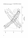
For this study, a visual tracking task was designed to measure the dynamic accuracy of each eye
camera. The output from this task does not reveal accuracy directly, but reveals how the
accuracy interacts with the eye-gaze location, when the system is reasonably calibrated.
Distortion and inconsistency are common especially at the edges of the functional range of each
device. Manufacturers' reported accuracy and resolution are also listed, including compatibility
with glasses and contact lenses.
Introduction
Calibration and ease of use
Constraints on calibration and ease of use are similar for simulated and actual driving. It must be
easy to place the unit on the driver's head and to make adjustments on the unit while the subject
is sitting in a vehicle.
Ease of calibration was evaluated generally, in this study, based on the amount of time, and
number of iterations and procedures that were required to obtain a reasonable calibration. A brief
description of the manufacturers' calibration procedures is also included.
Comfort
Subject comfort can significantly impact the outcome of a study. If a headpiece is intolerable or
uncomfortable, it will reduce the data collection time for each test session. Subjects may not be
motivated to cooperate or even participate if they feel discomfort due to the equipment. In many
cases, 30 minutes of use (including calibration time) is a tolerable limit for naive subjects,
(Testing on willing colleagues might be withstood longer.) The nature of discomfort associated
with wearing the headpieces is fully described, as well as rated for level of acceptance. Some of
the identified problem areas, such as imbalance of the headpiece, can be partially corrected by the
experimenters.
Safety
When using an on-head, eye-movement recorder for actual driving, the primary concern is the
performance of the driver: is the wearer safe to drive with the headpiece? Drivers' field of view
can greatly affect driver performance. A restricted field of view is not only unsafe for driving on
public roads, but also changes the natural state of driving. Drivers' eye fixation behavior and
related head movements will be altered by a reduced field of view. If a sensor or other part of the
headpiece is located directly in front of the eyes or face, it will interfere with vision and can be an
injury risk in the event of a collision. The field of view of each headpiece was mapped and the
areas of blockage, and their associated visual angles, identified.
Subjects' freedom of movement also affects safety. The cables and size of the unit must allow
the wearer to turn and move in the full range associated with normal driving conditions. As this
study was conducted in a laboratory, freedom of movement was based on wearer appraisal.
Excessive on-head unit weight also will also affect drivers' freedom of movement and behavior.
Of course, safety factors differ based on the test location. Safety is not as much of an issue for
simulator studies, at least in terms of collision, though a small field of view can unacceptably
change fixation behavior. If studies are carefully controlled, limited head movement may be
acceptable, but again could affect fixation behavior.
System Descriptions
All systems tested were infrared based. Two systems (ASL 210 and Ober2) use the relative light
reflections from different parts of the eye and eyelid to determine eye position. This method is
susceptible to interference from eyelashes and fatigue (which lowers the eyelids). One system
(NAC V) uses a single light reflected from the cornea to determine eye position. This method is
extremely sensitive to unit movement on the subject's head. The other two systems tested (ASL
4000 and ISCAN) use the relative locations of a light reflected from the cornea and the location of
the pupil to determine gaze direction. This two-point calculation is more accurate than singlepoint, and is less susceptible to slippage of a head-mounted eye camera, or turning of the subjects
head, for an off-head eye camera.
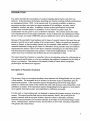
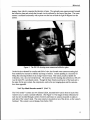
Applied Science Laboratories model 210 (ASL 210)
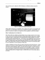
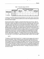
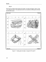
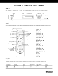
The Applied Science Laboratories model 210 is a modulated infrared based system. A photo
emitter with photo detectors on either side is aimed directly at each eye from below, at about 45
degrees (see Figure 1). One set of emitterldetectors measures the difference in reflectivity
between the iris and sclera
(for horizontal gaze
direction), the other set
measures the difference in
reflectivity between the
lower eyelid and the sclera
(for vertical gaze direction).
The assignment of eyes for
vertical and horizontal
measurement is determined
by the experimenter. The
optional scene camera is
mounted on a headband on
the forehead.
No modifications were done
to the device used for this
evaluation, although a rear
counterweight is
recommended to help
alleviate neck strain due to
forward imbalance.
Figure 1. The ASL 2 10 headset.
Materials
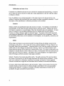
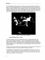
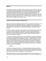
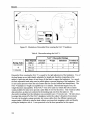
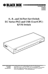
Applied Science Laboratories model 4000 (ASL 4000)
The Applied Science Laboratories 400Qseries is a near infrared based system. This system,
shown in Figure 2, uses a camera and infrared illuminator mounted above the forehead, aimed
downward at an infrared
coated visor, to obtain an
image of the eye with
corneal reflection and
bright pupil. The
system determines the
relative positions of the
center of the corneal
reflection and the brightpupil image and
computes the eye-gaze
direction. The optional
scene camera is mounted
below the visor, avoiding
parallax between the
computed eye position
and the scene. Darkpupil measurement can
be done with an optional
optic system.
The device tested had the
headband mounting and
had a scene camera as
shown in Figure 2,
except the camera was
Figure 2. ASL 4000 with helmet mount and horizontally mounted
mounted vertically. The
entire eye tracking
scene camera.
assembly had been
relocated to track the right eye. This was done to prevent the wearer, while driving, from hitting
the forward scene camera on the side window. A black cloth head-cover was attached to the top
of the visor and the headband to eliminate overhead light. A custom weight was attached to the
back of headband to reduce neck strain. To make the device functional in a vehicle for daytime
use, custom IR-filter coated plastic was being fabricated for blocking the side-incident light. This
configuration had not yet been tested.
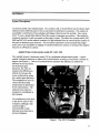
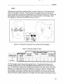
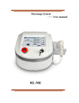
ISCAN Headhunter (ISCAN)
The ISCAN is an infrared based system. A camera and infrared light source are mounted above
the forehead on a helmet or a headband. The image of the eye is reflected onto the camera lens by
a circular, coated piece of glass, mounted at approximately a 45 degree angle, in front of the eye.
(See Figure 3.) The system uses a custom algorithm to track the corneal reflection and dark-pupil
Materials
images, from which it computes the direction of gaze. The optional scene camera mounts beneath
the reflective glass and records the forward view as reflected by the front of the glass. The scene
camera is mounted horizontally with.a prism over the lens to bend the light 90 degrees into the
camera.
Figure 3. The ISCAN showing scene camera and reflective glass.
On the device evaluated for comfort and field of view, the forward scene camera mounting had
been modified to increase its stability and range of motion. Custom padding is a necessity for
fitting the extra large helmet on an average wearer's head. This system, locally available for
evaluation, was a six-year-old prototype. The system used for tracking data collection at ISCAN
was the latest PC, card-based system. Though the basic function and layout of the head unit is
the same for the new system, the components, such as the eye imaging glass and the cameras,
have been upgraded.
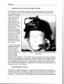
NAC Eye Mark Recorder model V (NAC V)
The NAC model V system uses two infrared LEDs, mounted below and in front of each of the
wearer's eyes, to create a corneal reflection. (See Figure 4.) The images of these reflections for
each eye are recorded through a series of mirrors and lenses, by cameras mounted on stalks to
each side of the wearer's head. The scene camera is mounted on top of the device, on the wearer's
forehead. This system is an old design, from before 1983.
Materials
For this experiment, the left camera unit was removed--since we only intended to calibrate the
right eye--for increased peripheral field of view, especially needed for driving. Removing half of
the device caused an imbalance, which was partially corrected with a counterweight. The original
padding was replaced by more extensive custom padding to increase comfort and stability. The
wires from the individual head camera units (the right eye camera, the scene camera, and the LED
power) were bundled together to allow freer movement, especially head turning.
Figure 4. The NAC model V headpiece.
Permobil Meditech Ober2 (Ober2)
The Permobil Meditech Ober2 is an infrared based system. The head-mounted part of the
system is a pair of goggles (see Figure 5). Each eye is surrounded by four arrays of pulsed
infrared diodes and detectors, arranged in a square, for determining the horizontal and vertical
position of each eye. The system consists of a PC, card-based control board to be installed into a
386 or 486 DOS machine. A small interface box connects the goggles to the board, and provides
electrical isolation.
Nothing was altered on the Ober2 for this experiment; however, wearer comfort would improve if
thin padding were added over the plastic edges that rest against the cheeks.
A supplementary video superposition PC card is being planned for this system. This would
allow the subject's eye fixations to be recorded onto video. It is not known if the video source
would be on- or off-head. If the video source were to be on-head, it would increase the size and
weight of the equipment worn by the subject.
Materials
Figure 5. The Ober2 goggles.
Equipment Specifications
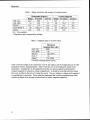
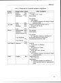
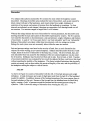
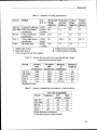
The systems described in the above section vary in functional range and accuracy. Table 1 shows
the range, precision, and accuracy of each system, as reported in their documentation. Precision
refers to the average angular error the system will have in measuring the distance the eye fixation
moves from one point to another. Accuracv refers to the average angular error the system will
have in identifying a given fixation location in real space. Note that the precision is generally
much better than the accuracy. Accuracy is more closely related to calibration than is precision.
The systems tested also vary by maximum sampling rate. The sampling rate for standard NTSC
video analysis is 30 Hz, the update rate of video. The values in Table 2 are the maximum
sampling rate for numeric data collection. The NAC model V is limited to 30 Hz because the data
are communicated to the output unit at the top of each video frame.
Materials
Table 1. Range, precision, and accuracy of systems tested.
I
1
Horizontal (degrees)
Range Precision Accuracy
0.25
+15
1
50
1-2
<0.5
NA
+15
0.5
NA
60
0.8-3.2 t
f25 1
0.05
0.5
ASL 210
ASL 4000
ISCAN
NAC Model V
/ Ober2
1
NA = Not available
"rependent upon compensation settings
1
Vertical (degrees)
Range Precision Accuracy
f15
1
2
40
<0.5
1-2
+15
0.5
NA
45
0.8-3.2 t
NA
f 2 0 1 0.05
1
Table 2. Sampling rates of systems tested.
ASL 210
ASL 4000
ISCAN
Maximum
Sampling Rate (Hz)
1000
60
60 (120t)
/ Ober2
120,1200t
?Possible with high speed version.
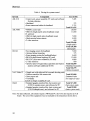
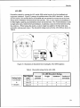
Table 3 lists the weight of all components worn by the subject, and the weight and size of other
equipment used for experimentation. Table 4 lists the cost of all components tested in this
experiment. Included here is all equipment (from the eye camera supplier and third-party
vendors) required for collection of data in digital form. It should be noted that all prices listed
here were in effect at the time of writing this report. They are subject to change at the supplier's
or manufacturer's discretion. Prices listed for equipment that would be purchased from other
vendors are based on an average of prices listed in current computer magazines.
Materials
Table 3. Weight and size of equivalent equipment configurations.
1 system
ASL 210
ASL 4000
ISCAN
1 Weight of Unit on Head /
Sensors
Headband
Scene camera
Total
Optics
Headband
60 g
220 g
170 g
450 g
280 g
227 g
Optics/cameras 160 g
Headband
185 g
Optional Helmet 455 g
Total (Headband)
345 g
Total (Helmet)
615 g
420 g
NAC Model V Head unit
Ober2
Goggles
80 g
Other Equipment
Control unit
3.6 Kg (31 x28 x 14 cm)
Video interface
Also requires:
Video monitor
PC compatible computer with Analog to Digital
conversion board.
Control unit rack (three monitors built-in)
36Kg (51 x48 x46 cm)
Video interface
Two monitors
Video interface
Also requires:
PC compatible computer for installation of
PupiVComeal Reflection Tracking and
Autocalibration System PC cards
:
Controller
2.5 Kg (180 x 70 x 280 rnm)
Viewfinder
230 g (40 x 53 x 155 mrn)
Data output unit
10 Kg ( 3 0 0 ~100 x240rnm)
Also requires:
PC compatible computer with Analog to Digital
conversion board
Goggle interface box
(15x 15x5cm)
Also requires:
PC compatible computer for installation of
Ober2 board and Video Eye Superimposed
Materials
Table 4. Pricing for systems tested.
1 S stem
1 ASL 210
Control unit, sensor assembly, PC cards and software
for data collection
Headband
Scene camera and cables for headband
ASL 4000
1
ISCAN
4000SU control unit
HMO-b (bright pupil) optics headband mount
Or, optional:
HMO-d (dark pupil) optics headband mount
Head-mounted scene camera
2 video monitors
7,495
375
3,755
1
1
Total $11,625
20,000
11.000
7,000
4,000
600
Total $35,600
(bright pupil)
Total $31,600
(dark pupil)
7,000
Eye imaging system for headband
Optional helmet mounting
575
scene imaging system for headbandhelmet
4,600
RK-426 pupil/corneal tracking (PC card)
13,000
RK-520 5 point auto calibration (PC card)
6,800
2 video monitors
600
Optional point-of-regard data acquisition and fixation Total $32,000
analysis software (additional $1350)
(Headband-mounted)
Total $32,575
(Helmet-mounted)
Goggle unit with right and left eyemark shooting units
Camera controller with remote unit
Total $15,000
Data output unit
Estimated value
Viewfinder
(no longerfor sale)
System no longer available for sale.
Standard goggles, junction Box, fast system card
Total $17,200
(1200 Hz samples max), and software for PC
(fast system card)
Standard goggles, junction Box, basic system card
Total $9,900
(120 Hz samples max), and software for PC
(basic system card)
1
Ober2
Note: For data collection, all systems require a 486-based PC; the NAC also requires an AD
board. The cost of this equipment was not included in the total prices shown above.
Materials
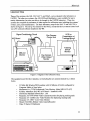
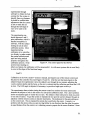
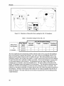
Three of the systems--the ASL 210, NAC V, and Ober2--were evaluated in the laboratory at
UMTRI. The other two systems--the ASL 4000 and Headhunter--were available for use in
nearby laboratories, but were not able to be brought to the UMTRI laboratory. These two
systems also required the assistance of other experts for calibration tests, including the systems'
owners, users, and manufacturers. The basic laboratory setup for the NAC V and ASL 210 is
shown in Figure 6. The set-up was similar for the Ober2, except that the eye camera control unit
was a PC card and software installed in the 486.
VCR for
Presentation of
T r a c k i m m y li
I
Tracking
Stimuli
Monitor
1
360 mm
Figure 6. Diagram of the laboratory setup.
The equipment used for this evaluation, not including the eye cameras themselves, is listed
below.
33 MHz 486 WindowfDOS machine with 16 MBytes of RAM, configured by
Computer Medic of Ann Arbor
Mediascan 4A+ TVM Professional Color Monitor, Model MD-14IV+(07)
Keithley MetraByte DAS 802 AD Board -- Installed in 486
DAS Series Standard Software Rev. 1.OO
Panasonic AG-1970 SVHS Video Cassette Recorder (for playing tracking task)
Panasonic CT-1320M Color Video Monitor (for displaying tracking task)
Panasonic CT-1383Y Color Video Monitor
Hitachi VM-H38A Hi8rnm Video Camera/Recorder
Fluke 70 Series I1 Multimeter
Materials
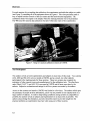
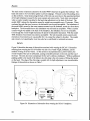
For each session of eye-tracking data collection, the experimenter sat beside the subject at a table
(see Figure 7) containing all of the equipment shown in Figure 6. This close proximity made it
easy to adjust both the controls of the eye camera and the head-mounted equipment. The
calibration sheets were taped to the display where the tracking stimulus was to be presented.
The 486 (used for numeric data collection) was also within easy reach of the experimenter.
Figure 7. Setup of a typical calibration session at UMTRI.
Test Participants
The authors served as both experimenters and subjects in most tests of this study. Two systems
(ASL 4000 and ISCAN) were not tested at UMTRI, and as a result, two other subjects
participated in the tracking tasks for these systems. These two systems also required the
assistance of other experts (users and manufacturers) for the calibration tests. The other three
units (0ber2, NAC V, and ASL 21 0) were used at UMTRI and all tests were done by the
authors. Subjective evaluations and ratings for all five systems were made by the authors.
Access to the systems not leased to UMTRI was limited to a few days. The authors relied upon
the assistance of people at those laboratories, and it was not possible to run repeated tests on a
large number of subjects. In order to keep testing conditions among systems as comparable as
possible, the authors served as subjects and experimenters in as many tests as possible. The
authors acknowledge this limitation, and only intend this report to provide insight into the
practical problems an experimenter may face when using one of these systems.
TEST METHOD
While there was not one set sequence of tests, as the testing conditions and locations varied, the
test protocol did follow a general order, Due to scheduling and rental periods, each system was
run through the test protocol thoroughly before moving on to the next system. While the
calibration procedure was being learned, the field-of-view testing could be completed with an
uncalibrated headpiece. After the calibration procedure was learned, the accuracy tasks were run.
Evaluations of headpiece discomfort (paidpressure, weight, imbalance, and freedom of
movement) were done concurrently with field-of-view and accuracy testing. No specific tests
were run for subject compatibility, safety, and in-vehicle use, but rather, these issues are
discussed based on the other test results and observations.
Calibration Procedure
For systems tested outside of UMTRI, the authors relied upon observation of, and comments
from, experts for information regarding calibration. Additional technical information, if needed
for explanation of the procedure, was obtained from the eye camera literature provided by the
manufacturer. For systems evaluated at UMTRI, the experimenters relied upon the system
documentation and practice, to become experts in the calibration procedure.
-
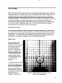
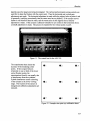
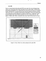
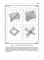
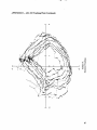
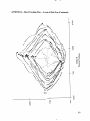
Field of View
To measure the wearer's
field of view and view
obstruction, a free-standingenclosure with grid lines
was constructed (see
Figure 8). The purpose of
this was to establish the
angular coordinates of the
visual boundary and the
angular location of other
view obstructions caused
by the eye camera
headpiece.
To measure wearer's field of
view, the eye camera was
placed on an experimenter's
head. The components of
the camera were moved to
the position they would be
in during data collection, but
the system was not
calibrated. The chin rest
Figure 8. The grid board with chin rest, used for
field of view measurement.
height was set so the subject's eyes were level with coordinate center. The visible field of view
was plotted for the areas of the board visible to both eyes. Areas of complete and partial visual
obstruction were distinguished. Using a pointer, the wearer traced the boundaries of view
obstructions caused by parts of the eye camera. View obstructions caused by facial features
were also traced. The experimenter marked the path followed by the pointer on a form which
duplicated the grid board. (All forms used in this study are in the Appendix.)
Safety
The level of safety associated with wearing these systems is dependent upon the application.
The characteristics of a system safe for use in a laboratory (simulator), are different from those
safe for an on-road vehicle driver situation. Safety can be divided into three main concerns:
(1) driver field of view; (2) driver freedom of movement; and (3) additional injury risk to the
driver in case of an accident. The first two involve not increasing the likelihood that an accident
will occur, while the third involves not increasing injury, should an accident occur.
The wearer's field of view determines how many potential accidents or unsafe situations the
wearer, as a driver, will detect. It also affects the wearer's scan pattern, forcing her or him to use
more head motion to see the mirrors and environment around the vehicle. Freedom of movement
interacts with the field of view. Restriction of movement, either by cables, weight, or imbalance,
exacerbates the risks resulting from field-of-view reduction. This included not only physical
-restriction, but subjects' motivation to move their heads based on comfort or annoyance.
Additional injury risk, in the event of an accident, is primarily risk of physical damage caused by
the hardware affixed to the subject's head. It is impossible to determine, without testing, if this
risk is increased or decreased by the presence of an airbag. There is also the possibility that,
post-accident, a subject may need to exit the vehicle unaided. The headgear andlor cables should
be easily removable by the subject.
The measurements of field of view, and the experimenters'judgment and experience will be used
to evaluate the systems on potential risks.
Discomfort
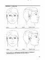
Subjects identified and evaluated common sources of discomfort from wearing the eye camera
headpieces. Subjects indicated the areas on the head where the device was causing discomfort.
The subject was given a drawing, depicting a profile and a front view of a head, for marking the
discomfort zones. Subjects were also free to make any other comments regarding the comfort of
the device.
Method
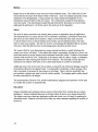
The subjects also rated the device for four comfort parameters: (1) pain and pressure, (2) weight,
(3) imbalance, and (4) freedom of movement. The following scale was used for these ratings:
1
2
3
4
5
6
7
8
9
JUG noticeable
Satisfactory
Just acceptable
Disturbing
Unbearable
Ratings occurred when there was a break between other evaluation tasks. Each system was rated
twice. Because some cameras were tested over several test sessions, not all ratings were done
during the same session. Copies of all forms are in the Appendix.
Accuracy
Accuracy is a measure of a system's ability to report the correct location of the subject's gaze.
For video analysis this means the eye-gaze location marker, added by the eye-camera system to the video image, is located correctly on the target object. For data analysis this means changes in
the gaze location are represented precisely by the numerical output. Data output was plotted
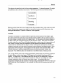
for each system for a set of four well-defined target paths, in order to provide a representation of
each system's accuracy that was comparable, and that captured both elements of accuracy.
Unless otherwise indicated, all four plots in each set were from the same session, with the same
calibration, and were run in the order of horizontal, vertical, diamond, and diagonal paths. These
target paths, shown in Figure 9, were designed to fill the majority of the functional field of the
systems tested and to represent different directional movement (horizontal, vertical, and
diagonal). These different paths were intended to reveal different kinds of tracking errors.
The viewing distance to the video monitor presenting the tracking tasks was 360 mm, resulting in
the tasks filling a vertical visual range of 30.8 degrees and a horizontal visual range of 40.2
degrees. The target was a 3 mm diameter black circle moving in a blue background. Black and
blue were used since most eye-gaze location markers are white. It was thought this would
facilitate monitoring of the eye-camera system video output. The tracking tasks were
programmed in Supercard and recorded to videotape using a RasterOps 24-STV 24 bit video card
and a RasterOps Video Expander 11. The videotape was then used for presenting the task to the
subjects.
Method
Figure 9, The four paths the target traced in the tracking tasks. (The arrow indicates where the
target began each path segment.)
First, coordinate data collection was set up for the system being tested. For some systems this
was built in, for others it was necessary to connect the eye-camera system analog outputs to an
analog to digital board in the experimental computer. The tracking stimulus videotape was
presented on a 13-inch monitor. During test sessions, the subject rested her head in a chin rest
mounted at the proper viewing distance. See Figure 10.
The subject was fitted with the eye camera and the system calibrated for targets at the distance of
the stimulus monitor screen. The chin rest was used during calibration. The data collection was
enabled and the tracking task tape started. Each of the four tracking tasks' data were recorded
separately. For most systems, data were collected from two subjects.
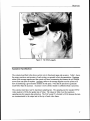
Subject Compatibility
Eye camera usefulness can be limited by restrictions on subject type. Limits include
incompatibility with some kinds of vision correction, shortened comfortable wear times due to
subject age and strength, and limitation on head size for a comfortable fit. Incompatibility with
Method
vision correction can be a physical conflict with glasses or calibration problems caused by
contacts.
Figure 10. Subject performing the tracking task.
Where reliable information on compatibility with eye glasses and contacts is not provided by the
manufacturer, we tested subjects with the type of correction in question. Incompatibility with
glasses is sometimes as simple as not being able to fit the eye glasses on with the eye camera.
Other Considerations for In-Vehicle Use
Other factors affect the usefulness and functionality of an eye-camera system if it is to be used
on road. Since all of the systems tested here are infrared based, infiared washout due to sunlight
is a primary concern. Systems that are well enclosed and have infrared coatings on the exterior
transparent surfaces should perform best. The drawback of this configuration, however, can be a
severe reduction in the driver's field of view. For systems that track the pupil, the small size of
the pupil in bright light can cause tracking difficulties, especially if the system is tracking a bright
pupil. Each system's ability to function in a bright infrared environment was determined, either
by our own experience, or by the experience of other users.
Another consideration is the size of the eye-camera control boxes and the need for power. If data
collection is to be done on road, the equipment must be safely and securely mounted in a vehicle.
If the head-mounted equipment is bulky , it may limit the driver height, or may limit where the
driver can move his or her head before striking the unit on the headrest or window. The wiring
between the headpiece and the control unit must be long enough to be placed around the driver
without restricting motion, and rugged enough to withstand the abuse it will inevitably suffer in
the vehicle.
RESULTS
The results of the evaluation were based on direct measurement, objective rating, and observation.
The calibration procedures described here are based on the descriptions in the documentation, or
on observations of experts calibrating a system. The field of view measurement was a direct
measurement, in the form of a plot, of the view obstructions imposed on the wearer. The
discomfort rating results are presented by system in table form, along with drawings of the areas
of discomfort. The plots of the output fiom the tracking task are also presented by system with
additional comments about what they indicate. An overall summary, with tables for comparison
across systems, is included at the end of this section.
Calibration Procedure Description and Observations
Each eye camera system's calibration procedure was learned.or observed for this evaluation. The
calibration procedures are summarized in this section. The procedures are only described in
detail enough to allow for comparison of complexity and difficulty. Any additional observations
and comments by the experimenters or experts describing difficulties with the procedures are
included.
In general, the quality of data output is directly related to the time and effort put into calibration.
For systems with manual calibration, output quality is a direct result of the experimenter's
experience level with fine tuning the calibration. The experienced experimenter has learned not
only the full function of all controls, but has strategies for dealing with anomalies different
subjects and environments can produce.
For systems with automatic calibration, more of the responsibility for good output has been put
in the hands of the programmers and designers of the system. The experimenter's main influence
on the output is installing the device optimally on the subject. Automatic calibration is a time
saver, and produces superior accuracy when conditions match those for which the system was
designed. However, automatic calibration systems can make it more difficult to troubleshoot
what part of the environment or the installation is causing eye tracking to fail. It is possible that
learning to use a manually calibrated device involves learning more extensively how conditions
interact with the device's functionality.
ASL 210
Eye fixation recording quality of the ASL 210 is primarily affected by the proper orientation of
the sensors. It is necessary to adjust the sensor location fiom the front and side of the wearer's
head, while having the subject look up and down, to make certain the alignment is proper through
the full range of eye movement. Eyelashes can be a serious disruption.
High precision calibration usually requires repeated adjustment of all controls (see Figure 11). A
nine-point fixation sheet is used for calibration (see Figure 12). The size of the calibration sheet
Results
depends upon the target area being investigated. The vertical and horizontal zeroing controls are
used first to align the fixation with the center point. Then the horizontal and vertical gain
adjustments are made. The horizontal adjustment is made while the subject looks at points 4 and
6 repeatedly (verifying occasionally that the center zero has not drifted). If the eyespot moves
farther in one direction than the other, and the center point is still aligned, then a linearity
adjustment is made. If the eyespot is affected vertically by eye motion in the horizontal, then a
crosstalk adjustment is made. The process is repeated for the vertical points 2 and 8.
Figure 11. The control box for the ASL 2 10.
The experimenter then checks the
accuracy of the remaining corner
points. If the eyespot behaves
erratically on one or both of the lower
corner fixation points, the
experimenters found it was usually due
to interference from the eyelashes.
Eyelash interference causes a skewing
of the eyespot in the lower viewing
range. The location of the sensors is
changed and calibration adjustments are
repeated.
Figure 12. Example nine-point eye calibration sheet.
Results
ASL 4000
The 4000 model configuration tested has automatic calibration, run by software on a DOS
computer. After the device is placed on the subject, the plastic visor (or window) in front of the
eyes is adjusted to give the eye camera a centered view of the subject's eye. The range of motion
allowed by the arms holding the window makes this task a little difficult. The forward camera is
then adjusted to show the subject's forward view. The arm mount for the camera has a broad
range of movement and tilt, which resulted in difficulty obtaining the subject's true forward view.
While the camera arm could be locked into position, it was not solid enough to keep it from being
bumped out of alignment.
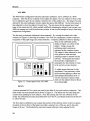
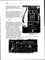
The first step in electronic calibration is done manually. By viewing the control rack video
monitor (see Figure 13) showing the system's view of the eye, adjustment is made to optimize
recognition of the pupil image and corneal reflection. Computer calibration is done by placing a
sheet of nine calibration points,
I
similar to Figure 12, in front of the
subject. Using a mouse, the
calibration point locations are
registered on the computer screen.
The subject is then instructed to look
at the points in order and each
resulting eyespot is entered into the
software. The program then makes
the necessary compensation to
subsequent eye movements to result
in the correct eye spot location.
Figure 13. Control panel of the ASL 4000.
I
To obtain proper function for this
experiment, it was necessary to dim
the fluorescent lighting to about onethird standard illumination level. It
was also necessary to place a black
cloth over the subject's head to block
the overhead light.
ISCAN
A helmet-mounted ISCAN system was used for the field of view and comfort evaluations. This
older model was rack-mounted and is shown in Figure 14. The helmet size was extra large and
required foam padding for most subjects. Since the tracking data were not collected on this
model, the calibration procedure described below is for the PC card-based model used by ISCAN
to collect the data.
The first steps in calibration was to adjust the position of the dichroic mirror so the eye camera
mounted on the top front of the helmet recorded a centered view of the eye, and to focus the
image of the eye. The threshold for pupil and corneal reflection is then adjusted by the
Results
experimenter through
software to obtain the best
contrast for the system to
identify these eye features.
It should be verified after
adjustment that the system
is able to track the eye
through the full range of
view to be used in the
study.
The experimenter can
decide between 5 and 9
point calibration, which is
handled completely in
software, with the subject
looking in turn at select
calibration points. Most
important during
calibration is to watch the
eye display to make certain
the corneal reflection and
pupil are being tracked
properly throughout
the
Figure 14. The control panel for the ISCAN.
calibration process. If the
system loses tracking on
either eye feature, the calibration will be unsuccessful. As with most systems this is most likely
to occur at the edges of the functional range.
-
-
NAC V
Calibration on the NAC model V system is manual, and requires use of the remote control and
the panel on the controller box (see Figures 15 and 16). After the unit has been placed on the
subject's head, the experimenter views the subject's eye through the eye camera, adjusting the
x and y position knobs and the focus, so the eye is centered and the reflection spot from the LED
is clear. The LED angle is adjusted, if necessary, to provide a bright spot on the eye.
The experimenter then switches (using the remote control) to monitor the scene camera and
instructs the subject to look in the center of a nine-point calibration chart. The x and y position
knobs are adjusted again to center the eye spot. The subject is then instructed to look at a point
to one side of center. To get the system to translate the eye spot the correct distance the gain is
adjusted, with the remote control, in discrete increments. The indicators for the gain setting are
on the control unit. This is repeated for points above and below the center. Linearity is a
problem with this device (the eye spot moving farther in one direction than the other for points
at equal distance fiom the center), as is obtaining correct eyespots for the comer fixations. Some
Results
Figure 15. The remote control for the
determining the eye location every sample, it
NAC model V.
can be set, for example, to alternate between
sampling the light level of the environment
and sampling the eye location. This way it can adapt to lighting changes in real-time. This is
effective unless the lighting is cycling rapidly.
Figure 16. The control box for the NAC model V.
22
Results
Changes to the sampling rate, visual distance, trial length, and other test conditions are made in
the software provided with the system.. The system is intended to be used with stimuli
programmed into and displayed by the computer. For the test sessions, a separate monitor
presented the tracking stimuli, so a dummy stimulus of text was presented by the Ober2
software. A programmed stimulus had to be loaded into the software to enable data collection.
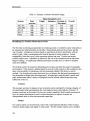
Field of View
Evaluations were conducted to assess subjects' fields of view while wearing the eye camera
headpieces. Areas of complete visual obstruction (such as opaque goggles), partial obstruction
(such as small sensors), and other distortions (such as reflections) are identified and labeled.
Every system that was tested had some obstruction. This information should be considered if
the system being evaluated has areas of blockage where an intended target will be, or if the
system will be used for studies of driving on public roads. Subjects may have to turn their head
more than usual to view a target (for example, to check a rearview mirror), or may decide not to
look at a target because of restriction of movement, or because of the headpiece weight. While
the validity of using an on-head eye recorder has not been verified, the less intrusive the system
is, the more natural (and valid) the subject's behavior will be.
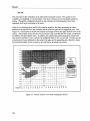
ASL 210
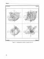
The field of view area that is blocked by the ASL 210 is caused by the three sensors that are
directly in front of each eye. (See Figure 17.) Because one eye is tracked for vertical movement
and the other eye for horizontal, it would not be possible to remove one of the sensors to
improve vision. The sensors, their mountings, and the forward scene camera, block a significant
portion of the direct forward scene, as well as the area above the horizontal center line. The exact
positioning of the sensors (and the area they block) will vary slightly for each subjects'
calibration configuration.
Results
Figure 17. Drivers' field of view while wearing the ASL model 2 10.
Results
ASL 4000
Sources of visual obstruction from the model 4000 were a seam in the visor, the forward scene
camera, and a custom light shield (a black cloth placed over the wearer's head). While the direct
forward gaze and peripheral view is unobstructed, the entire area above the horizon is completely
blocked. (See figure 18.) The black cloth was used to prevent interference from direct sun light
when used in a car, or in a laboratory with fluorescent ceiling lights. This test was with the cloth,
as this configuration had been prepared for in-vehicle use of the system. Additionally, a faint
distortion appears along a narrow band in the field of view due to a seam in the visor. This
ripple, or "double vision" effect, is noticeable when trying to read text that intersects this seam.
f K e v >
Partially
obscured
Degrees $
a a ; z a ! $ x? ?Y o, ?
s?;?$;v~
N
rn
8 , , e e S
Figure 18. Drivers' field of view while wearing the ASL model 4000.
Results
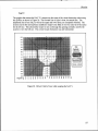
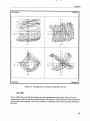
ISCAN
The unit used for this evaluation is an older helmet-mounted version. This system is now
available on a headband or a newer helmet. The newer versions were not available locally for
testing. Though the components themselves (the cameras, the reflecting glass) have been
upgraded, their basic positioning is the same.
Field of view blockage from the ISCAN tested is caused by the dome protecting the optics
attached to the helmet above the forehead, and the reflective glass and its supporting arm. (See
Figure 19.) The helmet of the ISCAN extends out enough to block the upper field of view of the
wearer. (The helmet used in this test was size Extra Large, and therefore the results would likely
be different for other helmet sizes.) In addition, the camera arm and focusing glass extend well
into the forward field of view, and into the peripheral field of view on one side, For this test, the
system had not been calibrated on the subject; the glass and its supporting arm,therefore, might
be positioned slightly lower or more to one side than in an actual test session.
Figure 19. Drivers' field of view while wearing the ISCAN.
Results
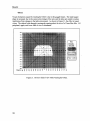
NAC V
The goggles that encase the NAC V's sensors are the cause of the visual obstruction when using
this system, as shown in Figure 20. The forward line of sight is clear, but tunnel-like. The
peripheral area of one side, as well as the upper and lower areas, are completely blocked. The
system used in this test had been modified to improve the field of view by removal of the optics
for the left eye. This allowed the wearer to see out through the opening normally used by the
system to view the left eye. The overall visual obstruction was still substantial.
Figure 20. Drivers' field of view while wearing the NAC V
Results
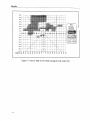
Visual obstruction caused by wearing the Ober2 is due to the goggle frames. The small square
shape is necessary due to the sensor array design of the unit, and the sides are sealed to reduce
interference from-changes in the light eniironment. As shown in Figure 21, the effect is tunnel
vision. The subject looks through rectangular opening about the size of a 35mrn film slide. All
peripheral, upper, and lower field of view is eliminated.
a
r pobscured
LZiy
1
I( ~ u lvisible)
l~ I
Figure 21. Drivers' field of view while wearing the Ober2.
Results
Discomfort
Two subjects (the authors) assessed the five systems for areas where the headpiece caused
discomfort. Drawings of problem areas indicate the type of discomfort, such as pain caused by
direct contact with part of the head piece, neck muscle strain from weight, imbalance or
restriction of movement, and regions of pressure from the headband or mountings. No time
intervals are indicated, as each camera's drawings are composites of all drawings made over all
test sessions. Test sessions ranged in length from 5 to 40 minutes.
Whereas the ratings indicate the level of discomfort for various parameters, the discomfort zone
drawings describe the type and location of discomfort experienced by wearers. The five cameras
were rated for discomfort on four dimensions: pain and pressure, weight, imbalance, and freedom
of movement. A scale of 1 to 9 was used, where 1 was "just noticeable" and 9 was "unbearable."
Ratings of discomfort were taken within three time intervals, with two ratings per system.
Ratings for each system were not necessarily taken within the same test session.
Pain and pressure ratings were based on the severity of head, face, or neck discomfort that
subjects felt while wearing an eye-camera headpiece. Subjects rated discomfort from the overall
weight, based on the level of discomfort to the head, face, or neck. The level of head, face, and
neck discomfort that was caused by the imbalance of the eye-camera headpieces was also rated for all systems. Imbalance may be perceived from side to side, front to back, or both. Freedom
of movement restriction was evaluated for how much the subjects felt they could move their head
without upsetting the stability of the headpiece. This factor included limitations that physically
restrict movement, such as short cables, the perceived fragility of the unit, and the possibility of
the headpiece striking the subject or vehicle interior.
ASL 210
As shown in Figure 22, sources of discomfort with the ASL 210 include pressure and weight
imbalance. A band of pressure and a spot of slight pain result from the tight fit of the headband
needed for stability. In addition, because of the forehead-mounting of the scene camera, there is
forward imbalance of the unit. Because of the forward bias, the headband must be fitted fairly
tightly, causing a "halo" of pressure around the forehead and downward pressure along the
eyebrows. Table 5 shows the ratings of discomfort from wearing the ASL 2 10.
Results
Figure 22. Illustration of discomfort from wearing the ASL 2 10 headpiece.
Table 5. Discomfort ratings for the ASL 2 10.
Rating Scale:
9
Unbearable
1
Time Elapsed
(min.)
0 to 15
16 to 25
26 to 35
ASL 210 Discomfort Ratings
Pain and
Weight
Imbalance Freedom of
movement
pressure
4
7
4
5
5
4
4
3
The most significant pain and pressure problem with the model 210 is caused by the headband.
Most of the pressure is against the forehead. The "halo" strap on the headband must be very
tight around the subject's head in order to stabilize the unit. Part of this problem is due to the
imbalance caused by the forward scene camera. In order to prevent the whole unit from slipping
forward, the head strap is adjusted as tightly as possible. The forward imbalance can also result
in downward pressure on the eyebrows. The discomfort from the weight of the model 2 10,
evaluated up to 35 minutes, was at the acceptable level. The scene camera on the front of the
model 210 headband causes the headpiece to be front-heavy. The discomfort resulting from this
imbalance was felt to be acceptable, up to the end of the evaluation period (35 minutes). The
reduction in discomfort rating after 25 minutes may be due to the wearer becoming accustomed to
the imbalance. Freedom of movement of the model 2 10 was within acceptable levels for the 35
minute test session. The main restriction on movement was perceived to be the cabling and the
weight imbalance.
Results
ASL 4000
Discomfort caused by wearing the ASL model 4000 results from the fit of the headband and
equipment imbalance. Figure 23 portrays the problem areas of the 4000's head unit. As there
are two sensors, one mounted above the forehead and one mounted on an arm next to the lower
cheek, there is imbalance toward both the front and side. This, in turn, requires the headband to
be fitted tightly, applying uncomfortable pressure around the head. The overall imbalance results
in slight neck strain, while the forward imbalance, in particular, causes downward pressure along
the eyebrows. (While testing this model, a custom weight was added to the back head strap,
noticeably reducing neck strain.) The discomfort ratings received by the ASL 4000 are shown in
Table 6.
Figure 23. Illustration of discomfort from wearing the ASL 4000 headpiece.
Table 6. Discomfort ratings for the ASL 4000.
I
9 Unbearable
Time Elapsed
(min.)
0 to 15
16 to 25
26 to 35
ASL 4000 Discomfort Ratings
Pain and
Weight
Imbalance Freedom of
movement
pressure
2
5
4
6
4
4
4
5
Results
The main source of pressure caused by the model 4000's head unit is against the forehead. The
head unit needs to be worn fairly tightly to prevent slippage. Pressure is also felt pushing down
on the eyebrows. Some strain along lhe back of the neck can occur due to the associated problem
of forward imbalance (caused by the scene camera and sensor units). Neck strain was reduced
when a counter weight was added to the head strap adjustment on the back of the head. The
model 4000's ratings for discomfort caused by weight was acceptable up to 25 minutes. When
evaluated beyond that time, however, the discomfort was beyond acceptable. The imbalance of
the model 4000, caused by the scene camera mounted over the forehead, results in a front-heavy
headpiece. The discomfort due to this imbalance was still rated as acceptable. When a custom
counter-weight was added to the back of the headpiece, the imbalance was not as noticeable.
Even though the overall weight increased, the perceived discomfort decreased. With the model
4000, freedom of movement was rated as acceptable. The side-mounted camera caused some
restriction of movement as it was possible for it to contact the subject's shoulder. The weight
and concern over upsetting the visor may also have contributed to restricted movement.
ISCAN
Figure 24 describes the areas of discomfort associated with wearing the ISCAN. Discomfort
resulting from wearing the ISCAN helmet was due to its overall weight, imbalance, and its
method of being fit to the wearer. As this system is incorporated into a pilot's helmet, the
overall weight of the unit is substantial, causing noticeable pressure on the neck and the top of
the head. The neck also must compensate for the unit's sideways imbalance. Without additionalpadding added to the inside of the helmet, the chin strap is the only means of fitting the helmet
on the head. The edge of the chin strap, coupled with its tight adjustment, was uncomfortable.
Ratings of discomfort are shown in Table 7.
Figure 24. Illustration of discomfort from wearing the ISCAN headpiece.
Results
Table 7. Discomfort ratings for ISCAN.
2
Time Elapsed
Rating Scale:
(min,)
1 Just noticeable
0 to 15
&
16 to 25
9 Unbearable
26 to 35
ISCAN Discomfort Ratings
Weight
Imbalance Freedom of
Pain and
movement
pressure
7
6
5
7
6
7
8
6
It should be noted that the helmet-mounted unit tested here was an older, heavier version than is
now available. Also this unit had been modified by the owners with components that may have
been heavier than the original.
Pressure from the ISCAN's headpiece is associated with the helmet and chin strap. While the
helmet helps to disperse the weight of the whole unit, there is still pressure concentrated on top
of the head. In order to stabilize the unit, the chin strap must be adjusted tightly, and, as there is
no padding along the edge of the strap, some discomfort is felt there also. Related to overall
weight, neck strain ("compression") was also reported. Lateral neck strain can also be felt, due to
imbalance caused by weight of the scene camera mounting. Discomfort from the weight of the ISCAN headpiece was unacceptable even for less than 15 minutes of use. The ISCAN is laterally
imbalanced, as the scene camera is mounted on a relatively heavy arm on the side of the helmet.
This imbalance was perceived to be more uncomfortable than the longitudinal (front-to-back)
imbalance of the other cameras. The ISCAN's imbalance, along with its weight, caused these
relatively higher ratings of discomfort. The rating of freedom of movement while wearing the
ISCAN was beyond the acceptable level. The tight chin strap made it uncomfortable for subjects
to turn their heads. Also, the helmet's weight and imbalance make it difficult to move the head.
NAC V
The majority of the discomfort from the NAC V is related to the front goggles, both in terms of
pressure and imbalance. Figure 25 depicts the areas of discomfort associated with the NAC V.
Because the top two head straps are not separately adjustable for length, the back head strap
must be tightened to prevent the headpiece from slipping. Pressure is thus felt along the forehead
and cheekbones, despite some extra padding inside the tested unit. The goggle nose opening may
not fit all wearers comfortably, resulting in the side of the nose contacting the hard plastic corner
of the goggles. The forward scene camera, mounted above the forehead, causes the headpiece to
be front heavy and puts strain on the rear of the neck. The ratings of discomfort for the NAC V
are shown in Table 8.
Results
Figure 25. Illustration of discomfort from wearing the NAC V headpiece.
Table 8. Discomfort ratings for NAC V.
I
9 Unbearable
1
Time Elapsed
(min.)
0 to 15
16 to 25
26 to 35
NAC V Discomfort Ratings
Pain and
Weight
Imbalance Freedom of
movement
pressure
6
5
5
3
6
6
6
7
Discomfort from wearing the NAC V is caused by the tight adjustment of the headpiece. Two of
the head straps are not individually adjustable for length and, therefore, depending on the
subject's head size and shape, do not always fit the head to support the headpiece. As a result,
the back adjustable head strap must be pulled tighter to prevent slipping of the headpiece. This
in turn causes pressure where the unit contacts the face (on the forehead and cheekbones). The
NAC V headpiece's weight is acceptable up to 15 minutes. Beyond that length of use, the
weight becomes unacceptable. If the NAC V were to be used in a vehicle the left eye sensor
would probably be removed to provide a safer field of view for the driver. This would not affect
data collection, as data were collected in the tracking task only fiom the right eye. The
discomfort resulting from this imbalance was acceptable up to 15 minutes only. The side sensorhousings that extend off of the NAC's headpiece restrict the subject's freedom of movement.
Not only do the plastic casings protrude, but various cables fiom the different cameras and
sensors make it difficult to turn the head without worrying about snagging a cable and thereby
pulling the headpiece with it. It was perceived to be the most precarious in this respect.
Results
Discomfort that results from wearing the Ober2, as shown in Figure 26, is associated with the
contact of the goggles to the face. The rubber edges of the goggles that serve to position the
sensors and prevent excess light from interfering, press into the area around the eye. Because the
plastic grips the skin of the face, the goggles do not need to be tight to avoid slippage, unlike
most headpieces. Ratings for discomfort are shown in Table 9.
Figure 26. Illustration of discomfort from wearing the Ober2 headpiece.
Table 9. Discomfort ratings for Ober2.
Rating Scale:
9 Unbearable
Time Elapsed
(min.)
0 to 15
16 to 25
26 to 35
Pain and
pressure
5
7
Ober2 Discomfort Ratings
Weight
Imbalance Freedom of
movement
2
4
2
3
1
1
The Ober2 goggles caused some pinching against the face. The plasticlrubber edges are not
rounded and therefore felt as if they were digging against the bridge of the nose and under the
eyes. The discomfort caused by this pinching was comparable to the other cameras' discomfort
problems. The weight of the Ober2 was satisfactory, even up to 35 minutes. The discomfort
from imbalance of the Ober2's headpiece was rated as acceptable even up to 35 minutes. The
simple goggles and minimal wiring of the Ober2 made restrictions on movement just noticeable.
The only wiring was ribbon cables that were bundled in the front and had a neck strap to remove
Results
the weight from the headpiece. Also, due to the rubber frame construction of the goggles, they
seemed more durable (and less injurious) than the metal components of the other systems.
The most prevalent cause of discomfort from the eye cameras tested was the headpieces'
physical mountings. No completely comfortable means of securely fitting the headpiece was
seen. Because absolute stability is imperative for calibration maintenance, the headpieces rely on
straps or bands that must be snug (sometimes beyond tolerable levels).
Another major comfort factor with most systems is imbalance. Sensors that are mounted high
and perched out over the eyebrows cause a significant imbalance. As a result, the headbands
must be tightly adjusted to prevent slippage. In this case, the neck still has much static tension
put on it. Although overall weight is a contributing factor, imbalance was felt to be a more
uncomfortable characteristic. A custom counterweight added to an imbalanced headpiece can
prolong a test session, provided the overall weight does not then become intolerable. To a limit,
if a tradeoff has to be made for weight or balance, a balanced system is preferred here.
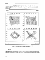
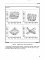
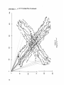
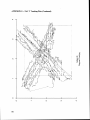
Accuracy
The numeric data collected from the eye camera systems were plotted to reveal the quality of t h e
data recording. Figure 9 in the Methods section shows the paths of the target. Unless otherwise
indicated, all four plots in each set were from the same session, with the same calibration, and
were run in the order of horizontal, vertical, diamond, and diagonal.
Some inevitable differences between systems are due to inconsistency in calibration. Some
systems had manual calibration and some had automatic. For the manual systems especially,
calibration can almost always be improved by additional (sometimes infinite) fine tuning. The
experimenters tried to limit calibration time to one-third of the total comfortable wear time. For
most systems, the total comfortable wear time was between 20 and 30 minutes. For the systems
on which the experimenters became experts only for this study (the ASL 210 and the Ober2),
calibration skill level was difficult to measure. If calibration for data collection did not proceed
well, or was taking excessive time, the experimenters assumed it was their own limitations, and
the tracking task was not run at that time.
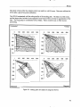
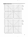
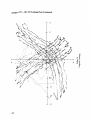
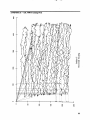
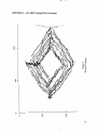
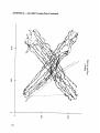
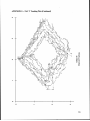
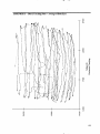
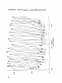
Each systems' accuracy can be seen in their plots (Figures 27 through 33). Straighter lines
indicate accuracy does not vary by location. If the horizontal and vertical plots are orthogonal,
this indicates consistent tracking near the edge of the range. A slight curvature in the plots of the
horizontal task is to be expected, since it reflects the curve of the video monitor used for
presentation.
Full page plots with data point markers are in the Appendix. Some aspects of eye camera
behavior are better indicated by those plots. The jumps from the tracking path are seen to
consist of only a few points diverging due to blinks. It is also more apparent that the jittery trace
of some systems, like the NAC model V, is due to discretely-quantized data.
I
Itill8
,#I.#,,
Results
ASL 210
~
-
.
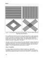
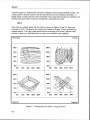
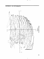
Plots fiom two subjects tested with the ASL 210 are shown in Figures 27 and 28. Data were
collected at 30 Hz.
For the ASL 210, the calibration sheet included in the user's manual was used. These points were
inside of the target's range of motion. As a result, the output at the outer edge of the plot
potentially could have been cleaner. For instance, the skewing in the lower right corner would
have been detected at calibration time, and possibly corrected. The bending to the bottom left
seen in the vertical tracking task demonstrates the interference caused by eyelashes. Eyelash
interference is worse closer to the bottom, since the subject's eyelids are lowest at this point.
The calibration of the 210 also was distorted by the parallax between the scene camera and the
subject's eye view.
Results
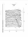
Horizontal
Vertical
-
Diamond
Diagonal
Figure 27. Tracking plots for subject A using the ASL 210.
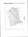
Results
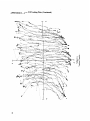
Horizontal
Vertical
Diamond
Diagonal
L
Figure 28. Tracking plots for subject B using the ASL 2 10.
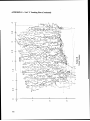
ASL 4000
Due to difficulties with the data collected by the experimenters, these plots (Figure 29) were
generated from data collected at Applied Science Laboratories. Data collection was performed by
expert staff at the company. Data were collected in a darkened room with nine-point calibration
at 60 Hz.
Results
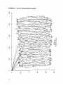
This system was calibrated for the comers and edges of the monitor. This helped the system
retain the orthogonality of the trace shapes. The jumps in the upper left comer are probably
caused by the system losing track ofone of the eye features.
Horizontal
Vertical
Diamond
Diagonal
Figure 29. Tracking plots for subject C using the ASL 4000.
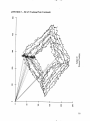
ISCAN
Data collection was not setup for the system the authors examined. Replacement data were run
(see Figure 30) by experts at the ISCAN company using the same protocol as the other systems.
Results
The latest version of the eye camera system was used in a well-lit room. Data were collected at
60 Hz after a quick five-point calibration.
The ISCAN maintained well the orthogonality of the tracking path. The data are a little noisy,
and the larger plots included in the appendix reveal some of this to be due to quantization of the
data. The long jumps to coordinates 0,O are blinks. These would be easy to filter in postprocessing.
Horizontal
0
Vertical
100
200
300
400
500
0
0
0
50
50
100
100
150
150
200
200
250
250
0
100
200
300
400
100
200
300
400
500
500
0
0
50
50
100
100
150
150
200
200
250
250
Diamond
Diagonal
Figure 30. Tracking plots for subject D using the ISCAN.
Results
NAC V
Plots from two subjects tested with the NAC model V are shown in Figures 3 1 and 32. Data
were collected at 30 Hz. The experimenters had the most experience calibrating and collecting
data from this system.
Horizontal
0
Vertical
1
2
3
0.5 a
0
4
I
0.5
1.5 --
2.5--
2.5 -.
3.5 --
3.5--
0
1
1
2
3
4
2
3
0
4
I
A
1.5 --
0
1
1
2
3
0.5 J.
4
I
1.5 --
2
2.5 --
3
3.5 -
Diamond
Diagonal
Figure 3 1. Tracking plots for subject A using the NAC model V.
Horizontal
Vertical
.
0
0
1
2
3
.
4
-1
1 --
1
2 --
2
3 --
3
4 -
4
0
1
2
0
1
2
3
4
0
1
2
3
4
0
4
3
4
0
0
1
1
2
2
3
3
4
4
Diamond
Diagonal
Figure 32. Tracking plots for subject B using the NAC model V.
This system has difficulty tracking the right eye to the upper right comer, as can be seen in the
vertical plots of both subjects. As it approaches the upper right comer, the eye marker jumps to
a much lower location due to the LED reflecting off the sclera. The system has only 8-bit
resolution for the horizontal and vertical. This causes the stair-step appearance of the diamond
and diagonal plots.
Results
Extensive practice is needed before consistent calibration can be obtained with this system. The
output quality is directly related to the time and effort put into the calibration procedure. A
higher quality of output may have been obtainable if more time had been spent on calibration, but
then the total session time would have exceeded the comfortable wear time.
Plots from two subjects tested with the Ober2 are shown in Figures 33 and 34. Data were
collected at 30 Hz. The data for the vertical plot of subject B (Figure 33) were collected in a
separate session. The x and y data plotted here are an average of the x and y data the Ober2
records for both eyes. Individual plots for each eye are included in the Appendix.
Horizontal
Vertical
2800 --
2800
2300 --
2300
1800 --
1800
1300 --
1300
800 -r
800
1300
1800
2300
2800
800
800
2800 --
2800
2300 --
2300
1800 -.
1800
1300 -.
1300
800
800
+
1300
1800
2300
2800
800
800
1300
1800 2300
2800
1300
1800 2300
2800
Diamond
Diagonal
Figure 33. Tracking plots for subject A using the Ober2.
Results
Horizontal
Vertical
2500 -2300 --
2500
2100 --
2100
1900 --
1900
1700 --
1700
1500 --
1500
1300 --
1300
I
1100 4
120 140 160 180 200 220 240 260 280
0 0 0 0 0 0 0 0 0
1100
120 140 160 180 200 220 240 260 280
0 0 ~ 0 0 0 0 0 0 0
2300
--
2500 --
2300 --
2300 --
2100 --
2100 --
1900 --
1900 --
1700 --
1700 --
1500 --
1500 --
1300 --
1300 --
I
1100
120 140 160 180 200 220 240 260 280
0 0 0 0 0 0 0 0 0
:
4
1100
120 140 160 180 200 220 240 260 280
0 0 0 0 0 0 0 0 0
2500
Diamond
Diagonal
Figure 34. Tracking plots for subject B using the Ober2.
The smooth lines are the result of high resolution. The anomalies are generally caused by blinks.
The foreshortening of some dimensions in the diagonal plots is due to the range of the system
being slightly smaller than the range of the tracking task.
Results
Subject Parameters
Some eye-movement monitoring systems can force experimenters to select from a restricted pool
of subjects. Factors such as weight, head size, comfortable wear time, and compatibility with
eyewear can limit the age, strength, body size, and vision correction of the subject base. Some
designs are more affected than others by users wearing eyeglasses or contacts. No system
evaluated in this test is able to function properly with a subject wearing bi- or trifocals.
The compatibility of each system with the subject parameters mentioned above is summarized
below.
ASL 210
Eyeglasses cannot be physically accommodated with the sensor array of the model 210. Hard
and soft contacts are acceptable, as they do not disrupt the function of this eye camera.
Experimenters had difficulty adjusting the headband to fit solidly on a small head without having
to overtighten the band across the forehead.
ASL 4000
Standard eyeglasses are compatible with this system, as are soft contacts. Hard contacts,
however, seriously disrupt the calibration of the system. The headband was difficult to fit
solidly on a small head, without sacrificing comfort.
ISCAN
Eyeglasses and contacts (both hard and soft) are compatible. The helmet version (weighing 0.5
kg) will place restrictions on the possible subject population, based on neck strength. The
headband version is much lighter and should not limit the pool based on strength.
NAC V
Eyeglasses are partially compatible. If glasses are worn by a subject, extra calibration effort is
necessary to avoid significant disruption to the output. Hard contacts can be used, but they add
noise to the eye spot movement. Soft contacts are compatible. The unit is limited in its
adjustability to various head shapes, especially small heads. This increases the discomfort for
subjects the unit does not fit correctly.
Eyeglasses will not physically fit with the goggles, though special goggles are available with
corrective lenses. There are no compatibility problems with contact lenses.
DISCUSSION
.
.
An overall ranking of the systems studied is difficult to make, for a number of reasons.
User needs vary significantly depending upon the experimental question. It is difficult
to predict all of these needs and to apply them to one overall comparison.
The systems were not equivalent and comparable. Some were manufacturers'
demonstration models, others had been modified by the customer/laboratory who was
using them, and one was a prototype.
Systems were not evaluated under all of the same conditions. Some were brought to the
UMTRI laboratory, others were evaluated at other laboratories, others were tested by
the manufacturer, and some were evaluated at multiple sites.
Results were taken from various sources, including manufacturers' specifications,
objective laboratory testing, direct observation, and subjective evaluation.
Summaries of the evaluations of each eye camera system are given below, along with tables
summarizing specifications and compatibilities across systems. Also included is a section of
issues to be addressed before selecting or using an eye camera for studies of driving.
Summaries of Each Camera
ASL 210
As a reminder, a demonstration model of the ASL 2 10, leased from Applied Science Laboratories,
was tested in an UMTRI laboratory. Overall, the system performed reasonably well for the
tests done. The major drawbacks include uncertainty about its safe and reliable use in an on-road
vehicle.
Calibrating the 21 0 is a moderately difficult task that requires a well-practiced experimenter.
More so than other systems, the 210's controls interact with each other. Adjusting one control
will improve the device's function on that dimension, simultaneously degrading it on another.
The controls and displays are straightforward, but require knowledge of the factors that influence
calibration accuracy. In terms of size, the control box is relatively compact and portable. The
assignment of eyes for horizontal or vertical movement sensing is at the experimenter's
discretion.
In terms of accurately tracking the moving stimulus, the results were reasonable. The main
problems were skewing of the data near the bottom of the functional range, and overall noise.
Potential use in a vehicle on the road is not known, nor is whether or not IR filtering would be
necessary. If IR does cause interference, then custom shielding would have to be constructed.
Discussion
When running a study with this system, researchers should expect that subjects will be
moderately uncomfortable after a 35-minute test session. A custom counterweight may reduce
some of the problem. In addition, if studies were to be done with regular drivers on public roads,
the risk associated with drivers' reduced vision and potential for injury should be carefully
considered. The subjects' field of view will be fairly restricted, especially in the central and
upper areas, due to the positioning of the sensors. The risk of injury would be eliminated in a
laboratory or fixed-base simulator; however, the field of view limitations and discomfort
problems would remain.
ASL 4000
The ASL model 4000 tracking task was conducted at the manufacturer's laboratory, according to
the test protocol developed by the authors. All other tests were conducted by the authors. The
overall performance of the model 4000 was very good, in regards to both technical results and
subject comfort. This model is one of the newest evaluated in this study.
Calibration of this system is semiautomatic, where the experimenter uses a mouse to indicate
calibration points. The system's tracking reliability is high.
The size and weight of the control units makes it fairly unwieldy. Currently, this system does
not function in a vehicle in daylight. It is not known if modifications will improve its function. There are difficulties with IR and the reduction in pupil size caused by bright sunlight. Shielding
the device from light may improve its function for on-road studies, but the subjects' field of view
could be impacted by altering the design. The system used for testing field of view in this study
had been modified to reduce overhead light interference. The reduction in overhead field of view
caused by this modification may be unacceptable for driving studies. Drivers may not be able to
see either traffic signals easily while stopped at an intersection, or approaching highway signs.
While there are no sensors directly in front of the eyes, the safety of the face plate visor in event
of an accident is unknown.
Discomfort problems for the wearer include a slight imbalance of the headpiece, As the overall
discomfort from the weight of the head unit is not great, a counterweight is an acceptable solution
to the problem of imbalance.
ISCAN
The ISCAN used in this study for field of view and comfort evaluation was being loaned by the
United States Air Force to Cybernet Systems Corporation, a company located close to the
authors' laboratory. Employees of the local company conducted a calibration session and the
authors conducted the remaining tests. (As a reminder, this unit is not the most recent model
offered by ISCAN.) The performance of the ISCAN was hampered by atypical difficulties
affecting calibration. (A striped screw prevented the experimenters from making stable
adjustments to the reflecting monocle.) The age of the system must be taken into account when
viewing the comfort ratings, as this system was installed on an older (and heavier) helmet than is
currently available. Also currently available is an even lighter headband version that would not
exhibit most of the comfort problems of this unit.
Discussion
Calibration of the ISCAN during this evaluation session was difficult due to a damaged screw
holding the reflective glass in place. As a result, the tracking task could not be completed at this
site, and data were subsequently collected by ISCAN. The calibration procedure for the newest,
PC-based unit is fully automated and software controlled. Based on the data collected by ISCAN
the tracking accuracy is high.
The older unit had been previously used successfully in a Humvee military vehicle. It is not
known what, if any, modifications were made for its use in-vehicle. The overall safety risk
associated with its use in a car seems relatively low, as there is only the dichroic mirror in front
of one eye and the unit is mounted within a padded helmet. The visual obstruction is very low,
except for some slight blockage due to the scene camera mounting arm,and the cover over the
optics and visor extending over the forehead. The older helmet resulted in poor subject comfort.
Its weight was enough to cause some discomfort immediately after fitting. The loose fit also
hampered freedom of movement. With some padding for stability, and a reduction in the overall
weight, this helmet-mounted unit would not be so cumbersome. The optional headband-mounted
unit was not evaluated.
NAC V
The NAC model V was tested by the authors at UMTRT. This unit has been accessible to the
authors on long-term loan from Mitsubishi Motors Corporation, and had been modified for use in
on-road experiments previously. The overall performance of the NAC was moderate, with the
drawbacks being headpiece instability and calibration difficulty, but the great advantage being
functionality in a high IR environment (such as a vehicle in sunlight). A newer NAC eye
movement recorder, the Model EMR 7, will be available soon in the United States, with a
redesigned headpiece. This new model is expected to have the same functionality when used in a
vehicle.
Calibrating the NAC V takes some practice to achieve an acceptable setting. Calibration requires
that adjustments be made to controls located on the headpiece. While other calibration controls
are on a remote unit, allowing the experimenter to make the on-head adjustments, care must be
taken not to jolt the headpiece out of its stable and semicalibrated position. Another large data
collection unit is also needed, but its proximity to the subject is not as limited by cable length.
Once a reasonable calibration is made, the tracking reliability is moderate.
Although not tested specifically for this study, this model has been used successfully by the
authors in a vehicle. The sides of the headpiece and coated face plate serve as a filter for IR.
Unfortunately, the headpiece frame that blocks out the IR also block the driver's field of view,
especially in the periphery, increasing the risk associated with driving. Also, as there is much
hard plastic material around the face, and an LED in front of one eye, the risk of injury in an
accident is likely increased. The size of the headpiece also results in discomfort to the subject.
The imbalance of the unit necessitates a tight (and uncomfortable) fit of the headpiece, to avoid
slippage. The number and placement of cables that are connected to the headpiece can cause
some restriction of head movement.
Discussion
The NAC V can be, and has been, modified to increase driver's field of view and comfortable
wear time. Removal of one side sensor piece not only creates a small side opening, but reduces
the overall weight of the unit. A small counterweight can compensate somewhat for the resulting
imbalance. Bundling the cables together can also improve the drivers' movement. While no
additional modification is needed to make the NAC V function in an on-road environment, the
limited field of view may make its use unsafe for on-road use.
The Ober2 system was leased from the manufacturer and tested at the authors' site. The system
for superimposing the eye mark on the forward scene had not been arranged to be leased by the
project director. The overall performance of the Ober2 was high. Subject discomfort was
minimal, and easily improved. Its adequacy for use in a car is not known, but the very limited
field of view would likely be unacceptable.
Calibration of the device is fully automated. The reliability of tracking is high. The
experimenter's only role is to define some parameters (such as lighting compensation, stimulus
viewing distance, etc.). As a result there is no control equipment and all adjustments are made in
software. The goggles are also very small and cause little discomfort to the wearer. The only
problem noticed was the edge of the goggles pinching into the face. As the sensors are encased in
soft plastic, no sharp objects are in front of the eyes. The most significant safety concern for use
in a car is the tunnel vision resulting from the goggle design. This limited visibility may be
suitable for use in a simulator, if the intended visual target areas are well defined and in a limited
range of view.
Overall summary of cameras
A summary of the specifications of the eye camera systems are shown in Table 10. This
information was taken from the manufacturers' literature. Table 11 shows a summary of field of
view (FOV) limitations and calibration difficulty, issues that affect the nature of the experimental
task and the acceptable length of test sessions. The compatibility of each camera's use with
various eye wear is listed in Table 12. Finally, a summary of the relative discomfort issues for
each of the tested systems is shown in Table 13.
Discussion
1
Table 10. Summary of system specifications.
System
ASL 210
1
ISCAN
I
I1 N ACV II
Ober2
Horizontal Vertical vertical
) Horizontal
1
Accuracy 1 Range 1 A C C u r a c ~
(degrees) (degrees) (degrees) (degrees)
1
Method
Varying IR reflection
Video, dual feature
identification
Vide0,dualfeature
identification
Video, single feature
identification
IR sensor array
/
1
$1 Range
f15
1
11,625 f 1 5
35,600 t 50
3 1.600tt
32,000 f 1 5
I
I
1 9,9009 1 f 25
t
Bright pupil system
*
Unit no longer for sale from supplier
9
120Hz maximum sampling
@$ 1200Hz maximum sampling
tt Dark pupil system
Table 11. Factors that may restrict the experimental task's target
location and test session length.
Weadband version
Table 12. Systems' compatibility with subjects' visual correction.
1
-
-
-
Eye wear compatibility
System Eyeglasses
Soft
Hard
contacts contacts
ASL 210
no
yes
ves
IASL40001
ves
I ves I no
ISCAN
yes
yes
yes
NAC V
no
yest
yes
1 0ber2
not?
yes
yes
?Some distortion of calibration
t.f.0ptionalcorrective lenses available
1
I
2
Discussion
Table 13. Summary of relative discomfort ratings.
1 System
ASL 210
IASL4000
ISCAN
NAC V
Ober2
1
Pain1
pressure
high
rned
high
high
high
Mean Discomfort Level
Weight
Imbalance Freedom of
Movement
med
low
low
rned
1 rned I rned /
high
high
high
med
high
high
low
low
low
I
/
1
1
1
Overall
med
rned
high
high
low
1
/
Identifying Eye Fixation Measurement Needs
The first step in selecting an appropriate eye-tracking system is to identify exactly what needs to
be measured and what limitations are tolerable. Measurement needs are the accuracy and the
type of output. Limitations are those placed on experiments by direct interference with the
subject's task. Safety considerations also limit the domain of testing situations. System
compatibility limits the type of vision correction subjects can wear. Comfort can restrict
possible subject types. Installation is affected by the size of the equipment and the maximum
length of cabling. A complicated calibration procedure can make use in a vehicle or simulator
much more difficult.
The method used by the system for determining eye location can affect the range of compatible
environments. If the system is infrared based (as were all of the systems in this evaluation), then
there is the possibility of interference with environmental infrared if the device is used in
sunlight. For the high-end systems that track two eye features, the dark-pupil measurement is
less susceptible to bright light, than bright pupil. In bright light, when the pupil is small, darkpupil measurement makes it easier to distinguish from the corneal reflection and other stray
reflections on the eye.
Accuracy
The necessary accuracy (in degrees of eye movement) can be calculated by drawing a diagram of
the experimental setup and measuring the visual angle between typical objects of interest. If
accuracy needs are on the border of a given eye system's capability, build a simple mockup and
have the vendor demonstrate the unit to ensure that glances to objects of interest are
distinguishable both on video and processed output data.
Output
Eye camera output is in several forms, video (with a superimposed indication of the eye-gaze
location), analog output, and digital or serial output. The first usually requires only a standard
Discussion
VCR; the second and third require a computer, interfacing, and data collection software. Both
methods require additional data processing. Video data is usually analyzed by a person, though
multimedia tools can make this a less arduous task. Computer data collection needs postprocessing to determine fixations, transitions, and blinks.
If the gaze is measured relative to the head, computer data collection is meaningless unless the
subject's head is fixed, or the data are analyzed with respect to a concurrent video recording. To
record relative to the scene, the position of the subject's head also needs to be recorded.
For studying actual driving, it is necessary to have video output with a cursor indicating the eyegaze location. Video output is the only means for identifying the object of the driver's fixation,
especially if a head tracker is not used. If a head tracker is used, eye movements to objects fixed
inside of the vehicle could be determined from a spatial mapping of the objects in the driver's field
of view. This would not allow for identification of gazes to anything not fixed, such as the road
scene, or objects in the car that move, like a cellular phone handset. Video output would also be
necessary for recognizing when calibration has slipped or drifted. Some loss over time of
calibration due to road vibration and driver head motion is inevitable during testing of actual
driving.
For studies conducted in a simulator, video output is still the most reliable means of determining
fixation locations. It is possible, with a head tracker and eye camera, to determine the object of
each gaze since the controls in the vehicle are fixed, and the objects in the scene and their locationare known at each moment. Video is still useful for determining the reliability of the data.
Objects that usually move relative to the driver, like a remote control for a navigation system, can
be studied only by video analysis, unless they are permanently mounted in the driver's field of
view.
Eye camera interference with the experimental task
Use of an eye camera, especially an on-head system, can interfere with the subject's natural
performance of the experimental task. It is necessary to determine how much interference is
acceptable before the test results will be significantly impacted or, in the case of on-road studies,
the subject will no longer be safe. Items to be identified with regard to interference:
The field of view needed by the subject to perform the task.
Degrees of freedom of movement needed by the subject such that natural motion is
not impeded. If freedom of movement is not needed, a bite-bar or cheek-rest greatly
increase the accuracy of the data.
The space around the subject's head needed to give the subject free movement when
the eye camera is being worn.
The total test time for each session. Ensure the system will be comfortable for the
needed time period.
The time for eye-camera calibration that can be spared from the total comfortable
wear time. For most systems, higher accuracy means spending more time fine tuning
the calibration, or calibrating the system for more points.
Discussion
Physical structures, such as short cables and bulky headpieces, may limit drivers' freedom of
movement in a car. Cables that are too short restrict head movements or cause the headpiece to
slip off the head. On the other hand, if cables are too long, or are not tied together, they can get
caught on other equipment or on the subject. Headpieces that are very large may not provide
enough headroom for a tall subject in a car. Other mounting devices that protrude from the
headpiece may contact the side window or headrest, causing the headpiece to slip on the head
(and lose calibration) and potentially block the subjects' view of the road.
Likewise, if a headpiece is heavy, imbalanced, or obtrusive, it may interfere with the normal head
movements and eye-glance behavior that occur with driving a car. Excessive weight and
imbalance can cause neck strain, making it difficult or uncomfortable for subjects to turn their
heads to check mirrors or displays. Thus, drivers may reduce their head movements or change
their behavior to reduce muscle fatigue or discomfort. On the other hand, components of the
headpiece that block the wearers view of the road or target may cause them to alter their glance
behavior just to avoid the obstructions. Also, if the headpiece's method of being fastened to the
head (e.g., adjustable straps) is not adequate and secure, subjects may be reluctant to move
because the headpiece may slip.
Safety
Before running any subjects in on-road studies, especially public roads, the risk associated with
the subject's task must be evaluated. The evaluation should consider at least the following
issues:
(1)
(2)
(3)
The increase in difficulty of safely performing the driving task due to reduced field
of view and reduced motion from cable restrictions or weight.
Crashworthiness of the head-mounted unit. The risk of injury from parts of the
eye camera, especially in front of the wearer's face. The risk of injury due to
broken pieces of the eye camera flying about.
All supporting eye camera control units and recording equipment must be secured
so they can not break loose and cause injury.
Subject constraints
Eye-camera systems may be limited in the type of subjects on which they can be successfully
calibrated. Usually this is caused by visual correction disrupting the eye camera's function. Soft
contacts are not generally a problem, but hard contacts can cause serious problems, and glasses
often will not fit with the physical head unit. These limits need to be considered if the
experimenters intend to draw from a broad subject pool, especially including older drivers, who
often have corrected vision.
Comfort can also limit the segment of the population to be used in eye fixation studies. Eye
camera weight limits the age of subjects to be run,or at least the length of comfortable wear time
for some subjects.
Discussion
Equipment size
Acquiring space for control and recording equipment is more difficult for in-vehicle studies than
laboratory studies, though it is an issue for both. The space required for each type of system
varies, as does the flexibility of system configuration. Some systems are piecemeal and the types
of displays and computers are at the experimenter's discretion. This allows for acquisition of
small, low-power units for in-vehicle use, or large, cheaper units if lab space is not a problem.
Cable length restricts the distance from the eye camera to the control and recording equipment.
This can affect setup in a simulator, and can impact wearer freedom of movement in a vehicle
setup.
Usability
Usability is convenience for accessing controls on a control box, a computer, and the on-head unit
while seated in a vehicle. For a simulator laboratory or an actual vehicle, it may be difficult to
install all control units within easy reach of the experimenter. If adjustments are required
alternately on different units, it can be difficult for one person to access both. The most usable
eye camera system for a vehicle setting is one where the units can be calibrated serially--finish
one unit, move on to the next--so the experimenter is not forced to move repeatedly between
units.
-
REFERENCES
Applied Sciences Laboratories, Eye Tracking Systems Handbook, Waltham, M A . (No date.)
Green, P. (1992). Review of Eye Fixation Recording Methods and Equipment, (Technical Report
UMTRI-92-28). Ann Arbor, Michigan: The University of Michigan Transportation
Research Institute.
APPENDIX A -- Manufacturers' Contact Information
Applied Science Laboratories
335 Bear Hill Road
Waltham, MA 02 154
Tel: (617) 890-5 100
Fax: (617) 890-7966
ISCAN Inc.
125 Cambridgepark Drive
P.O. Box 2076
Cambridge, MA 02238
Tel: (617) 868-5353
Fax: (617) 868-923 1
NAC Visual Systems
Instrument Marketing Corporation
1011-F West Alameda Ave
Burbank, CA 9 1506
Tel: (8 18) 840-27 11
Fax: (818) 840-6898
NAC Image Technology & Equipment
2-7, Nishi-Azabu 1-Chome
Minato-ku
Tokyo, Nippon
Tel: 03-3404-2321
Fax: 03-3479-8842
Permobil Meditech
6B Gill Street
Woburn, MA 0 1801
Tel: (617) 932-9009
Fax: (617) 932-0428
Permobil Meditech AB
Box 120
S-861 00
Tirnra, Sweden
Tel: 46-60-572606
Fax: 46-60-575250
-
APPENDIX B Field of view form
System:
Eye used:
Date:
Subject:
APPENDIX C - Comfort form
Camera:
Date:
Subject:
Duration of wear:
Camera:
Date:
Subject:
Duration of wear:
Drawings adapted from: ,4nthropometric Source Book Volume 11: A Handbook of
,Anrthro~ometricData, NASA Publication 1024, July 1978, pp. 35.
APPENDIX D -- ASL 210 Tracking Plots
APPENDIX D -- ASL 210 Tracking Plots (Continued)
APPENDIX D
-- ASL 210 Tracking Plots (Continued)
APPENDIX D -- ASL 210 Tracking Plots (Continued)
APPENDIX E - ASL 4000 Tracking Plots
0
.
T
.
--
APPENDIX E ASL 4000 Tracking Plots (Continued)
APPENDIX E -- ASL 4000 Tracking Plots (Continued)
APPENDIX E -- ASL 4000 Tracking Plots (Continued)
APPENDIX F -- ISCAN Tracking Plots (Continued)
APPENDIX F -- ISCAN Tracking Plots (Continued)
APPENDIX F -- ISCAN Tracking Plots (Continued)
APPENDIX G -- NAC V Tracking Plots
APPENDIX G -- NAC V Tracking Plots (Continued)
APPENDIX G -- NAC V Tracking Plots (Continued)
APPENDIX G -- NAC V Tracking Plots (Continued)
--
APPENDIX H -- Ober2 Tracking Plots Average of Both Eyes
APPENDIX H -- Ober2 Tracking Plots -- Average of Both Eyes (Continued)
--
APPENDIX H -- Ober2 Tracking Plots Average of Both Eyes (Continued)
APPENDIX H
-- Ober2 Tracking Plots - Average of Both Eyes (Continued)