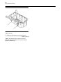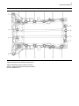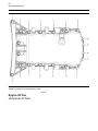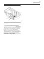
1
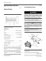
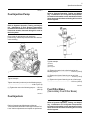
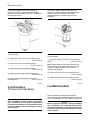
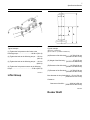
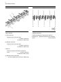
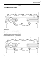
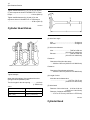
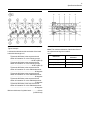
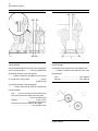
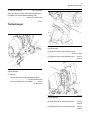
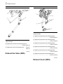
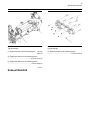
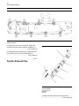
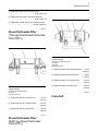
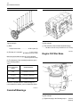
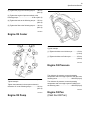
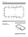
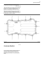
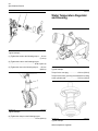
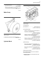
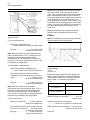
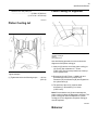
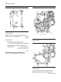
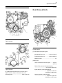
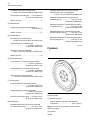
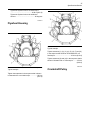
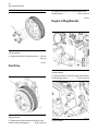
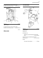
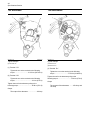
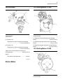
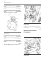
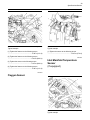
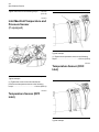
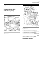
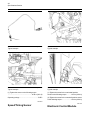
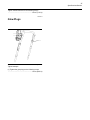
Service Manual
854E Diesel Engine
Specifications
854E model is for FD70N Chassis Service Manual.
99709-5B101
FOREWORD
This service manual describes the specifications, maintenance, and service procedures for 854E
Diesel Engine of Mitsubishi Forklift Trucks.
To maintain the performance of the engine for many years and to ensure safe operation, it is
important to use the engine correctly and conduct regular inspection and maintenance, and also
to take necessary measures which involves the disassembly, inspection, repair, and assembly of
the engine and engine parts.
Read this manual carefully and understand the work procedures fully before disassembling,
inspecting, repairing, or assembling the engine.
The contents of this manual are based on the engine models that are being produced at the time
of publication. Due to improvements made thereafter, the actual engine that you work on may
differ partially from the one described in this manual.
Pub.No. 99709-5B101
Specifications
854E-E34TA and 854F-E34T Industrial
Engines
JR (Engine)
JS (Engine)
JT (Engine)
Important Safety Information
Most accidents that involve product operation, maintenance and repair are caused by failure to observe
basic safety rules or precautions. An accident can often be avoided by recognizing potentially hazardous
situations before an accident occurs. A person must be alert to potential hazards. This person should
also have the necessary training, skills and tools to perform these functions properly.
Improper operation, lubrication, maintenance or repair of this product can be dangerous and
could result in injury or death.
Do not operate or perform any lubrication, maintenance or repair on this product, until you have
read and understood the operation, lubrication, maintenance and repair information.
Safety precautions and warnings are provided in this manual and on the product. If these hazard
warnings are not heeded, bodily injury or death could occur to you or to other persons.
The hazards are identified by the “Safety Alert Symbol” and followed by a “Signal Word” such as
“DANGER”, “WARNING” or “CAUTION”. The Safety Alert “WARNING” label is shown below.
The meaning of this safety alert symbol is as follows:
Attention! Become Alert! Your Safety is Involved.
The message that appears under the warning explains the hazard and can be either written or
pictorially presented.
Operations that may cause product damage are identified by “NOTICE” labels on the product and in
this publication.
Mitsubishi Forklift Trucks cannot anticipate every possible circumstance that might involve a
potential hazard. The warnings in this publication and on the product are, therefore, not all
inclusive. If a tool, procedure, work method or operating technique that is not specifically
recommended by Mitsubishi Forklift Trucks is used, you must satisfy yourself that it is safe for
you and for others. You should also ensure that the product will not be damaged or be made
unsafe by the operation, lubrication, maintenance or repair procedures that you choose.
The information, specifications, and illustrations in this publication are on the basis of information that
was available at the time that the publication was written. The specifications, torques, pressures,
measurements, adjustments, illustrations, and other items can change at any time. These changes can
affect the service that is given to the product. Obtain the complete and most current information before
you start any job. Mitsubishi forklift truck dealers have the most current information available.
When replacement parts are required for this
product Mitsubishi Forklift Trucks recommends
using Mitsubishi replacement parts.
Failure to heed this warning can lead to premature failures, product damage, personal injury or
death.
3
Table of Contents
Table of Contents
Specifications Section
Engine Design ......................... ......................... 4
Fuel Injection Lines...................... ..................... 4
Fuel Injection Pump..................... ..................... 5
Fuel Injectors .......................... .......................... 5
Fuel Filter Base (Secondary Fuel Filter Base). 5
Fuel Filter Base (Primary Fuel Filter Base)... ... 6
Fuel Manifold (Rail)...................... ..................... 6
Lifter Group............................ ........................... 7
Rocker Shaft........................... .......................... 7
Valve Mechanism Cover.................. ................. 9
Cylinder Head Valves ................... .................. 10
Cylinder Head......................... ........................ 10
Turbocharger ......................... ......................... 13
Exhaust Gas Valve (NRS) ............... ............... 14
Exhaust Cooler (NRS) .................. .................. 14
Exhaust Manifold...................... ...................... 15
Flexible Exhaust Pipe ................... .................. 16
Diesel Particulate Filter (Through Flow Diesel
Particulate Filter (DPF)) ................ ................ 17
Diesel Particulate Filter (Wall Flow Diesel
Particulate Filter (DPF)) ................ ................ 17
Camshaft ............................ ............................ 17
Camshaft Bearings ..................... .................... 18
Engine Oil Filter Base ................... .................. 18
Engine Oil Cooler...................... ...................... 19
Engine Oil Pump....................... ...................... 19
Engine Oil Pressure.................... .................... 19
Engine Oil Pan (Cast Iron Oil Pan) ........ ........ 19
Engine Oil Pan (Aluminum Oil Pan)........ ....... 22
Engine Oil Pan (Pressed Steel Oil Pan) .... .... 24
Crankcase Breather.................... .................... 25
Water Temperature Regulator and Housing .. . 26
Water Pump.......................... .......................... 27
Cylinder Block......................... ........................ 27
Crankshaft ........................... ........................... 28
Connecting Rod Bearing Journal.......... .......... 29
Main Bearing Journal................... ................... 30
Connecting Rod....................... ....................... 30
Piston and Rings ...................... ...................... 31
Piston Cooling Jet...................... ..................... 33
Balancer .......................................................... 33
Front Housing and Covers............... ............... 34
Gear Group (Front)..................... .................... 35
Flywheel .......................................................... 36
Flywheel Housing ...................... ..................... 37
Crankshaft Pulley ...................... ..................... 37
Fan Drive ............................ ............................ 38
Engine Lifting Bracket................... .................. 38
Alternator ............................ ............................ 39
Starter Motor.......................... ......................... 41
Coolant Temperature Sensor............. ............. 42
Boost Pressure Sensor (If equipped) ...... ....... 42
Oxygen Sensor........................ ....................... 43
Inlet Manifold Temperature Sensor (If
equipped)........................... ........................... 43
Inlet Manifold Temperature and Pressure Sensor
(If equipped)......................... ......................... 44
Temperature Sensor (DPF Inlet)........... .......... 44
Temperature Sensor (DOC Inlet).......... .......... 44
Pressure Sensor (NOx Reduction System).. .. 45
Temperature Sensor (NOx Reduction System) 45
Speed/Timing Sensor ................... .................. 46
Electronic Control Module ............... ............... 46
Glow Plugs .......................... ........................... 47
Index Section
Index................................ ............................... 48
4
Specifications Section
Specifications Section
i05240674
i04134174
Fuel Injection Lines
Engine Design
Contact with high pressure fuel may cause fluid
penetration and burn hazards. High pressure fuel
spray may cause a fire hazard. Failure to follow
these inspection, maintenance and service instructions may cause personal injury or death.
Refer to Operation and Maintenance Manual,
“General Hazard Information and High Pressure Fuel
Lines” before adjustments and repairs are performed.
Illustration 1
g01353215
Cylinder and valve location
(A) Inlet valve
(B) Exhaust valve
Bore ................................................99 mm (3.90 inch)
NOTICE
Refer to Systems Operation, Testing, and Adjusting, “Cleanliness of Fuel System Components”
for detailed information on the standards of cleanliness that must be observed during ALL work on
the fuel system.
Ensure that all adjustments and repairs are
performed by authorized personnel that have had the
correct training.
Stroke ............................................110 mm (4.33 inch)
Displacement........................................3.4 L (207 in3)
Cylinder arrangement ........................................In-line
Type of combustion ..............................Direct injection
Compression ratio
Turbocharged aftercooled .......................... 17.5:1
Number of cylinders .................................................. 4
Valves per cylinder .................................................... 2
Firing order .....................................................1, 3, 4, 2
When the crankshaft is viewed from the flywheel end
of the engine, the crankshaft rotates in the following
direction: .........................................Counterclockwise
When the camshaft is viewed from the flywheel end
of the engine, the camshaft rotates in the following
direction: .........................................Counterclockwise
Note: The left side and the right side of the engine
are viewed from the flywheel end. The No. 1 cylinder
is the front cylinder.
Illustration 2
g02501177
Typical example
(1) Tighten the screws to the following torque.
...........................................................10 N·m (89 lb in)
(2) (3) Torque for the nuts on the fuel injection lines
............................................................25 N·m (18 lb ft)
5
Specifications Section
i05240671
Fuel Injection Pump
NOTICE
Refer to Systems Operation, Testing and Adjusting, “Cleanliness of Fuel System Components”
for detailed information on the standards of cleanliness that must be observed during ALL work on
the fuel system.
NOTICE
Refer to Systems Operation, Testing, and Adjusting, “Cleanliness of Fuel System Components”
for detailed information on the standards of cleanliness that must be observed during ALL work on
the fuel system.
Ensure that all adjustments and repairs are
performed by authorized personnel that have had the
correct training.
Illustration 4
g03342579
Typical example
(2) Clamp
(4) Washer
(5) O ring seal
(3) Tighten the studs in the cylinder head to the
following torque...................................20 N·m (15 lb ft)
Illustration 3
g02621683
Typical example
Tighten the studs (not shown) to the following torque.
............................................................18 N·m (13 lb ft)
(1) Tighten the injector fastening nut to an initial
torque..................................................15 N·m (11 lb ft)
(1) Tighten the injector fastening nut to a final torque.
............................................................25 N·m (18 lb ft)
i05240679
(1) Tighten the nuts to the following torque. .....25 N·m
(18 lb ft)
i05240672
Fuel Filter Base
(Secondary Fuel Filter Base)
Fuel Injectors
Refer to Operation and Maintenance Manual,
“General Hazard Information and High Pressure Fuel
Lines” before adjustments and repairs are performed.
NOTICE
Refer to Systems Operation, Testing, and Adjusting, “Cleanliness of Fuel System Components”
for detailed information on the standards of cleanliness that must be observed during ALL work on
the fuel system.
6
Specifications Section
If necessary, install a new fuel filter element to
canister (6). Refer to Operation and Maintenance
Manual, “Fuel System Secondary Filter - Replace” for
the correct procedure.
Illustration 5
If necessary, install a new fuel filter element to
canister (2). Refer to Operation and Maintenance
Manual, “Fuel System Primary Filter (Water
Separator) Element - Replace” for the correct
procedure.
g02621258
Illustration 6
Typical example
g02606186
Typical example
(1) Tighten the connections to the following torque.
............................................................25 N·m (18 lb ft)
(2) Tighten the screw to the following torque.
..........................................................2.5 N·m (22 lb in)
(1) Tighten the water in fuel sensor to the following
torque................................................2.5 N·m (22 lb in)
(3) Tighten the screw to the following torque.
............................................................17 N·m (13 lb ft)
Note: Tighten water in fuel sensor until the O-ring
seal comes into contact with the bowl of the water
separator. Tighten the water in fuel sensor an
additional 180 degrees.
(4) Tighten the setscrews to the following torque.
............................................................25 N·m (18 lb ft)
(3) Tighten the connection to the following torque.
............................................................20 N·m (15 lb ft)
(5) Tighten the fuel temperature sensor to the
following torque...................................22 N·m (16 lb ft)
(4) Tighten the setscrews to the following torque.
............................................................44 N·m (32 lb ft)
i05240680
i04424550
Fuel Filter Base
(Primary Fuel Filter Base)
NOTICE
Refer to Systems Operation, Testing, and Adjusting, “Cleanliness of Fuel System Components”
for detailed information on the standards of cleanliness that must be observed during ALL work on
the fuel system.
Fuel Manifold (Rail)
Refer to Operation and Maintenance Manual,
“General Hazard Information and High Pressure Fuel
Lines” before adjustments and repairs are performed.
NOTICE
Refer to Systems Operation, Testing and Adjusting, “Cleanliness of Fuel System Components”
for detailed information on the standards of cleanliness that must be observed during ALL work on
the fuel system.
7
Specifications Section
Illustration 7
g02621238
Typical example
g02488296
Typical example
(1) Tighten the fuel pressure relief valve to the
following torque.................................100 N·m (74 lb ft)
(2) Tighten the bolts to the following torque......25 N·m
(18 lb ft)
(3) Tighten the bolts to the following torque......10 N·m
(89 lb in)
(4) Tighten the fuel pressure sensor to the following
torque..................................................70 N·m (52 lb ft)
i04332521
Lifter Group
Illustration 8
(B) 26 mm (1.02362 inch)
(D) 38 ± 0.25 mm (1.49606 ± 0.00984 inch)
(A) Diameter of the lifter body......... 14.780 ± 0.04 mm
(0.58189 ± 0.00157 inch)
(C) Height of the lifter body .................... 67 ± 0.25 mm
(2.63779 ± 0.00984 inch)
(E) Diameter of the lifter body......... 14.970 ± 0.02 mm
(0.58937 ± 0.00079 inch)
(F) Diameter of the lifter body ......... 14.780 ± 0.04 mm
(0.58189 ± 0.00157 inch)
Bore diameter in the cylinder block ... 15.4 to 15.6 mm
(0.60630 to 0.61417 inch)
Clearance
Clearance of the lifter .............. 0.020 to 0.054 mm
(0.00079 to 0.00213 inch)
i04823040
Rocker Shaft
8
Specifications Section
Illustration 9
g02842156
Illustration 10
g02681778
Typical example
Tightening sequence
(1) Inlet rocker arm
Tighten the fasteners in the sequence that is in
illustration 10 . Tighten the fasteners to the following
torque.................................................10 N·m (89 lb in)
Diameter of the rocker arm bore
............................................19.020 to 19.033 mm
(0.74882 to 0.74933 inch)
(2) Exhaust rocker arm
Diameter of the rocker arm bore
............................................19.020 to 19.033 mm
(0.74882 to 0.74933 inch)
Clearance
Maximum clearance of both the rocker arm
bores. ...................................... 0.020 to 0.054 mm
(0.00079 to 0.00213 inch)
(3) Diameter of the rocker shaft
.........18.979 to 19.000 mm (0.74720 to 0.74803 inch)
9
Specifications Section
i04335229
Valve Mechanism Cover
Illustration 11
g02490536
Typical example
Tighten the M6 fasteners (1), (2), (3), (4), (5), (6) and
(7) in the sequence shown in illustration 11 to an
initial torque. ........................................5 N·m (44 lb in)
Tighten the M8 fastener (8) in the sequence shown in
illustration 11 to an initial torque........10 N·m (89 lb in)
Illustration 12
Typical example
g02727663
10
Specifications Section
Tighten the M6 fasteners (1), (2), (3), (4), (5), (6) and
(7) in the sequence shown in illustration 12 to a final
torque.................................................10 N·m (89 lb in)
Tighten the M8 fasteners (8), (9) and (10) in the
sequence shown in illustration 12 to a final torque.
............................................................25 N·m (18 lb ft)
i04335069
Cylinder Head Valves
Illustration 14
g01335204
(2) Valve face angle
Inlet ..................................................... 30 degrees
Exhaust .............................................. 30 degrees
(3) Valve stem diameter
Inlet.......................................... 7.985 to 8.000 mm
(0.31437 to 0.31496 inch)
Exhaust ...................................7.985 to 8.000 mm
(0.31437 to 0.31496 inch)
Clearance
Clearance of the inlet valve stem
...... 0.040 to 0.053 mm (0.00157 to 0.00209 inch)
Clearance
Illustration 13
g01335203
Typical example
Clearance of the exhaust valve stem
...... 0.040 to 0.053 mm (0.00157 to 0.00209 inch)
(4) Length of valve
When the valve springs (1) are replaced the valve
springs must be replaced in pairs.
The free length for the valve spring ............... 44.6 mm
(1.75590 inch)
Inlet valve and exhaust valve
............................................ 132.75 to 133.15 mm
(5.22637 to 5.24212 inch)
(5) Valve head
Table 1
The load for the valve spring
The length of the valve spring
270 N (61 lb)
34 mm (1.33858 inch)
528 N (119 lb)
23.8 mm (0.93701 inch)
Diameter of inlet valve head ... 41.43 to 41.69 mm
(1.63110 to 1.64134 inch)
Diameter of exhaust valve head
...... 37.27 to 37.53 mm (1.46732 to 1.47756 inch)
i04894560
Cylinder Head
11
Specifications Section
Illustration 15
g03005658
Typical example
Lubricate the threads and the underside of the head
bolts with clean engine oil.
Tighten the M15 bolts in the sequence that is
shown in illustration 15 to the following torque.
...................................................130 N·m (96 lb ft)
Tighten the M12 bolts in the sequence that is
shown in illustration 15 to the following torque.
.....................................................65 N·m (48 lb ft)
Tighten the M15 bolts in the sequence that is
shown in illustration 15 to the additional amount.
............................................................ 90 degrees
Tighten the M12 bolts in the sequence that is
shown in illustration 15 to the additional amount.
............................................................ 90 degrees
Tighten the M15 bolts in the sequence that is
shown in illustration 15 to the additional amount.
............................................................ 70 degrees
Tighten the M12 bolts in the sequence that is
shown in illustration 15 to the additional amount.
............................................................ 60 degrees
Minimum thickness of cylinder head ................ 90 mm
(3.54330 inch)
Illustration 16
g02490336
Note: The maximum distortion of the bottom face of
the cylinder head is given in table 2.
Table 2
Dimension
Maximum Permissible
Distortion
Width (A)
0.05 mm (0.00197 inch)
Length (B)
0.05 mm (0.00197 inch)
Diagonal Line (C)
0.05 mm (0.00197 inch)
12
Specifications Section
Illustration 17
g02328933
Illustration 18
g02474819
Typical example
Typical example
(D) Valve guide height from the top of the valve guide
to the valve spring seat............ 6.5 mm (0.25590 inch)
(J) Diameter of the parent bore in the cylinder head
......... 12.960 to 12.995 mm (0.51024 to 0.51161 inch)
(E) Outside diameter of the valve guides
......... 12.950 to 12.985 mm (0.50984 to 0.51122 inch)
(K) Seat angle
(F) Length of the valve guides .......................... 56 mm
(2.20472 inch)
Inlet .................................................. 59.5 degrees
Exhaust ...........................................59.5 degrees
(G) Internal diameter of the valve guides
.............8.023 to 8.038 mm (0.31587 to 0.31646 inch)
(H) Valve depths
Inlet........ 0.3 to 0.7 mm (0.01181 to 0.02756 inch)
The service limit for the depth of the inlet valve
..........................................0.9 mm (0.03543 inch)
Exhaust ........................................... 0.3 to 0.7 mm
(0.01181 to 0.02756 inch)
The service limit for the exhaust valve depth
.............................................1 mm (0.03937 inch)
Illustration 19
Typical example
g02847819
13
Specifications Section
(L) Seat surface finish ......................... Ra 0.5 microns
(M) Concentricity of valve seat to valve guide parent
bore Maximum Total Indicated Reading (TIR)
............................................... 0.05 mm (0.00197 inch)
i05239446
Turbocharger
Illustration 21
g02626267
Typical example
(2) Tighten the studs to the following torque.
............................................................15 N·m (11 lb ft)
(3) Tighten the nuts to the following torque. .....25 N·m
(18 lb ft)
Illustration 20
g02626265
Typical example
(1) Actuator
The test pressure for the wastegate actuator
...........................................170 kPa (24.6568 psi)
The movement for the rod actuator............ 10 mm
(0.3937 inch)
Illustration 22
g02626269
Typical example
(4) Tighten the bolt to the following torque. ......22 N·m
(16 lb ft)
(5) Tighten the bolts to the following torque......25 N·m
(18 lb ft)
14
Specifications Section
Illustration 24
g02626260
Typical example
(1) Tighten the setscrews to the following torque.
...........................................................10 N·m (89 lb in)
Illustration 23
g02626270
Typical example
(6) Tighten the setscrew to the following torque.
............................................................25 N·m (18 lb ft)
(7) Tighten the nut to the following torque. .......25 N·m
(18 lb ft)
i05239430
Exhaust Gas Valve (NRS)
(2) Tighten the setscrews to the following torque.
............................................................40 N·m (30 lb ft)
(3) Tighten the setscrews to the following torque.
............................................................20 N·m (15 lb ft)
(4) Tighten the setscrews to the following torque.
............................................................20 N·m (15 lb ft)
(5) Tighten the setscrews to the following torque.
............................................................20 N·m (15 lb ft)
(6) Tighten the setscrew to the following torque.
............................................................20 N·m (15 lb ft)
i04426264
Exhaust Cooler (NRS)
15
Specifications Section
Illustration 25
g02621805
Illustration 26
g02909156
Typical example
Typical example
(1) Tighten the nuts to the following torque. .....25 N·m
(18 lb ft)
(1) Tighten the studs to the following torque.
............................................................18 N·m (13 lb ft)
(2) Tighten the fastener to the following torque.
..........................................................3.5 N·m (31 lb in)
(3) Tighten the fastener to the following torque.
...........................................................10 N·m (89 lb in)
i05239453
Exhaust Manifold
16
Specifications Section
Illustration 27
g02725251
Typical example
(2) Tighten the nuts to an initial torque. Tighten the
nuts in the sequence that is shown in Illustration 27.
...........................................................10 N·m (89 lb in)
(2) Tighten the nuts to a final torque. Tighten the nuts
in the sequence that is shown in Illustration 27.
............................................................27 N·m (20 lb ft)
i05287664
Flexible Exhaust Pipe
Illustration 28
g03180056
Typical example
(1) Tube assembly
(4) Bellows
(6) Elbow
(2) Tighten the ball clamp to the following torque.
............................................................35 N·m (26 lb ft)
17
Specifications Section
(3) Tighten the clamp to the following torque.
............................................................55 N·m (41 lb ft)
(5) Tighten the ball clamp to the following torque.
............................................................35 N·m (26 lb ft)
(7) Tighten the V-band clamp to the following torque.
.........................................................12 N·m (106 lb in)
i05287843
Diesel Particulate Filter
(Through Flow Diesel Particulate
Filter (DPF))
Illustration 30
g03358816
Typical example
(3) Diesel Particulate Filter (DPF)
(4) Clamps
(5) Clamps
(6) Mounting bracket
(1) Tighten the bolts to the following torque........9 N·m
(80 lb in)
(2) Tighten the bolts to an initial torque...............8 N·m
(71 lb in)
(2) Tighten the bolts to a second torque. ..........16 N·m
(12 lb ft)
Illustration 29
g03358495
Typical example
(2) Tighten the bolts to a final torque. ...............25 N·m
(18 lb ft)
(2) Diesel Particulate Filter (DPF)
(3) Clamps
(4) Mounting bracket
i05239470
(1) Tighten the bolts to an initial torque...............8 N·m
(71 lb in)
(1) Tighten the bolts to a second torque. ..........16 N·m
(12 lb ft)
(1) Tighten the bolts to a final torque. ...............25 N·m
(18 lb ft)
i05287571
Diesel Particulate Filter
(Wall Flow Diesel Particulate
Filter (DPF))
Camshaft
18
Specifications Section
Illustration 31
g02844377
Illustration 32
g02608336
Typical example
Typical example
(1) Bolts
(1) The diameter of the installed camshaft bearing
.........54.083 to 54.147 mm (2.12925 to 2.13177 inch)
Torque for the bolts ......................25 N·m (18 lb ft)
(2) End play of a camshaft..................... 0.1 to 0.3 mm
(0.00394 to 0.01181 inch)
i05240691
Engine Oil Filter Base
Maximum permissible end play of a worn camshaft
..................................................0.3 mm (0.01181 inch)
(3) The diameters of the camshaft journals are given
in the following tables.
Table 3
Camshaft Journals from
the Front End of the
Engine
Standard Diameter
1
Front
53.995 to 54.045 mm
(2.12578 to 2.12775 inch)
2, 3 and 4
49.975 to 50.025 mm
(1.96752 to 1.96948 inch)
5
Rear
39.975 to 40.025 mm
(1.57382 to 1.57578 inch)
Check the camshaft lobes for visible damage. If a
new camshaft is installed, you must install new lifters.
i04411212
Camshaft Bearings
Illustration 33
g02659546
Typical example
(1) Tighten the plug to the following torque. .....30 N·m
(22 lb ft)
19
Specifications Section
(2) Tighten the plug to the following torque. .....30 N·m
(22 lb ft)
(3) Tighten the engine oil pressure switch to the
following torque...................................35 N·m (26 lb ft)
(4) Tighten the bolts to the following torque......25 N·m
(18 lb ft)
(5) Tighten the filter to the following torque. .....30 N·m
(22 lb ft)
i05240850
Engine Oil Cooler
Illustration 35
g02501357
Typical example
(1) Tighten the bolts to an initial torque.............15 N·m
(11 lb ft)
(1) Tighten the bolts to a final torque. ...............25 N·m
(18 lb ft)
i04333169
Engine Oil Pressure
Illustration 34
g02871598
Typical example
Tighten the setscrews in the sequence shown in
illustration 34 to the following torque. ..............22 N·m
(16 lb ft)
i04346369
Engine Oil Pump
The minimum oil pressure at normal operating
temperature and at an engine speed of 750 rpm is the
following value. .................................. 200 kPa (29 psi)
The minimum oil pressure at normal operating
temperature and at an engine speed of 2400 rpm is
the following value. ............................ 400 kPa (58 psi)
i05288769
Engine Oil Pan
(Cast Iron Oil Pan)
20
Specifications Section
Illustration 36
g02676701
Typical example
(1) Tighten the drain plug to the following torque.
............................................................50 N·m (37 lb ft)
Tighten the fasteners (2) to a torque of 70 N·m
(52 lb ft). Tighten the fasteners in sequence that is
shown in illustration 37.
21
Specifications Section
Illustration 37
Tightening sequence for the deep tunnel oil pan
Tighten the fasteners (2) to a torque of 70 N·m
(52 lb ft). Tighten the fasteners in sequence that is
shown in illustration 38.
g02904098
22
Specifications Section
Illustration 38
g02904216
Tightening sequence for the flat bottom oil pan
i04790655
Engine Oil Pan
(Aluminum Oil Pan)
23
Specifications Section
Illustration 39
g02906220
Typical example
(1) Tighten the drain plug to the following torque.
............................................................50 N·m (37 lb ft)
Tighten the fasteners (2) in sequence that is shown in
illustration 40. Tighten the M8 fasteners to an initial
torque of 7.5 N·m (66 lb in). Tighten the M10
fasteners to an initial torque of 13.5 N·m (10 lb ft).
Tighten the fasteners (2) in sequence that is shown in
illustration 40. Tighten the M8 fasteners to a final
torque of 25 N·m (18 lb ft). Tighten the M10 fasteners
to a final torque of 45 N·m (33 lb ft).
24
Specifications Section
Illustration 40
g02906221
Tightening sequence
i04789574
Engine Oil Pan
(Pressed Steel Oil Pan)
Illustration 41
Typical example
g02904316
25
Specifications Section
(1) Tighten the drain plug to the following torque.
............................................................50 N·m (37 lb ft)
Tighten the fasteners (2) in sequence that is shown in
illustration 42. Tighten the M8 fasteners to an initial
torque of 7.5 N·m (66 lb in). Tighten the M10
fasteners to an initial torque of 13.5 N·m (10 lb ft).
Tighten the fasteners (2) in sequence that is shown in
illustration 42. Tighten the M8 fasteners to a final
torque of 25 N·m (18 lb ft). Tighten the M10 fasteners
to a final torque of 45 N·m (33 lb ft).
Illustration 42
g02904337
Tightening sequence for the pressed steel oil pan
i05239495
Crankcase Breather
For the correct procedures to remove and install the
crankcase breather, refer to Disassembly and
Assembly, “Crankcase Breather - Remove” and
Disassembly and Assembly, “Crankcase Breather Install”.
26
Specifications Section
i04335212
Water Temperature Regulator
and Housing
Illustration 43
g02721003
Typical example
(1) Tighten the studs to the following torque.......8 N·m
(71 lb in)
(2) Tighten the insert to the following torque.
............................................................85 N·m (63 lb ft)
(3) Tighten the nuts to the following torque. .....10 N·m
(89 lb in)
Illustration 45
g02842121
Typical example
Torque for the vent plug ......................40 N·m (30 lb ft)
Torque for the bolts (1) and (2) that fasten the housing
to the cylinder head ............................25 N·m (18 lb ft)
Illustration 44
g02621860
Typical example
(4) Tighten the clamps to the following torque.
.............................................................5 N·m (44 lb in)
Illustration 46
Typical example
Water temperature regulator
g00906121
27
Specifications Section
Opening temperature..........................77° to 81°C
(171° to 196°F)
Maximum open length of 11.5 mm (0.45276 inch)
is achieved at the following temperature.
..................................................... 130° C (266° F)
i04335189
Water Pump
Illustration 48
g02488336
Typical example
(1) Cylinder block
(2) Cylinder bore ............................ 99.00 to 99.02 mm
(3.8976 to 3.8984 inch)
(3) Camshaft bearings
Illustration 47
g02490498
Typical example
(1) Tighten the setscrews to the following torque.
............................................................25 N·m (18 lb ft)
i04332590
Cylinder Block
Diameter of the bushing in the cylinder block for
the number 1 camshaft bearing
............................................ 59.222 to 59.248 mm
(2.33157 to 2.33259 inch)
Diameter of the bore in the cylinder block for
numbers 2, 3 and 4 camshaft journals
.............................................50.069 to 50.119 mm
(1.97122 to 1.97319 inch)
Diameter of the bore in the cylinder block for the
number 5 camshaft journal
.............................................40.069 to 40.119 mm
(1.57752 to 1.57949 inch)
(4) Main bearings
Bore in the cylinder block for the number 1, 2, 3
and 4 main bearings............ 80.588 to 80.614 mm
(3.17275 to 3.17377 inch)
Bore in the cylinder block for the number 5 main
bearings .............................. 87.588 to 87.614 mm
(3.44834 to 3.44936 inch)
(5) Main bearing cap bolts
Use the following procedure in order to install the
main bearing cap bolts:
1. Apply clean engine oil to the threads of the main
bearing cap bolts.
28
Specifications Section
2. Put the main bearing caps in the correct position
that is indicated by a number on the top of the main
bearing cap. Install the main bearing caps with the
locating tabs in correct alignment with the recess in
the cylinder block.
3. Evenly tighten the main bearing cap bolts.
Initial torque for the main bearing cap bolts......50 N·m
(37 lb ft)
Final torque for the main bearing cap bolts. .....80 N·m
(59 lb ft)
4. After torquing the bolts for the main bearing caps,
the bolts must be rotated for an additional 90
degrees.
Note: Ensure that the crankshaft can rotate freely.
i04605731
Crankshaft
Illustration 49
g02155393
Typical example
(1) Crankshaft gear
(2) Crankshaft
(3) Crankshaft thrust washers
Maximum permissible temperature of the gear for
installation on the crankshaft .............. 180 °C (356 °F)
Maximum permissible temperature of the timing gear
for the balancer (if equipped) for installation on the
crankshaft ........................................... 180 °C (356 °F)
Note: Refer to Disassembly and Assembly for the
correct procedure to remove and install the timing
gear for the balancer.
The end play of a new crankshaft........ 0.1 to 0.41 mm
(0.00394 to 0.01614 inch)
Standard thickness of thrust washer
.................2.69 to 2.75 mm (0.10591 to 0.10827 inch)
29
Specifications Section
Illustration 50
g02155394
Typical example
(4) Journal 1
(5) Journal 2
(6) Journal 3
(7) Journal 4
(8) Journal 5
Refer to table 4 for the run out of the crankshaft
journals.
Table 4
Journal
Run out of the Journals
(1)
Mounting
(2)
0.03 mm (0.00118 inch)
(3)
0.03 mm (0.00118 inch)
(4)
0.03 mm (0.00118 inch)
(5)
Mounting
Inspect the crankshaft for wear or for damage. For
more information regarding the servicing of the
crankshaft, contact the authorized Mitsubishi
forklift truck dealer.
Refer to Specifications, “Connecting Rod Bearing
Journal” for more information on the connecting rod
bearing journals and connecting rod bearings.
Refer to Specifications, “Main Bearing Journal” for
information on the main bearing journals and for
information on the main bearings.
i04332830
Connecting Rod Bearing
Journal
The original size of the connecting rod bearing journal
on the crankshaft .......................71.970 to 71.990 mm
(2.83346 to 2.83425 inch)
Maximum permissible wear of a bearing journal on
the crankshaft when a new connecting rod is installed
...............................................0.04 mm (0.00157 inch)
Width of the connecting rod bearing journals on the
crankshaft ..................................37.962 to 38.038 mm
(1.4946 to 1.4976 inch)
Radius of the fillet of the connecting rod bearing
journals ........ 1.6 to 1.7 mm (0.06299 to 0.06693 inch)
Surface finish of connecting rod bearing journals
............................................Ra 0.3 microns maximum
Surface finish of radii ......... Ra 0.3 microns maximum
30
Specifications Section
i04332763
Main Bearing Journal
i04479212
Connecting Rod
The original size of the main bearing journal
.........83.980 to 84.000 mm (3.30629 to 3.30708 inch)
Maximum permissible wear of the main bearing
journals ..................................0.040 mm (0.0016 inch)
Radius of the fillet of the main bearing journals
.............3.875 to 4.125 mm (0.15256 to 0.16240 inch)
Surface finish of bearing journals and crank pins
.............................................................Ra 0.2 microns
Surface finish of radii .......................... Ra 0.4 microns
Width of new main bearing journal where the thrust
washer is installed .....................35.235 to 35.165 mm
(1.3872 to 1.3844 inch)
Width of new main bearing journal where the thrust
washer is not installed ...................35.25 to 35.15 mm
(1.38779 to 1.38386 inch)
The shell for the main bearings
The shells for the main bearings are available for
remachined journals which have the following
oversize dimensions.
Oversize bearing shell ...... 0.127 mm (0.005 inch)
Oversize bearing shell ...... 0.254 mm (0.010 inch)
Oversize bearing shell ...... 0.508 mm (0.020 inch)
Thickness at center of the shells of oversize bearing
shell 0.25 mm (0.010 inch) ........... 2.226 to 2.232 mm
(0.08764 to 0.08787 inch)
Thickness at center of the shells of oversize bearing
shell 0.50 mm (0.020 inch) ........... 2.353 to 2.359 mm
(0.09264 to 0.09287 inch)
Thickness at center of the shells of oversize bearing
shell 0.76 mm (0.030 inch) ........... 2.480 to 2.486 mm
(0.09764 to 0.09787 inch)
Width of the main bearing shells ... 26.32 to 26.58 mm
(1.03622 to 1.04645 inch)
Clearance between the bearing shell and the main
bearing journals ............................. 0.032 to 0.102 mm
(0.00126 to 0.00402 inch)
Illustration 51
g02859356
Typical example
(1) The bearing shell for the connecting rod
For the correct procedure to install the bearing shell
for the connecting rod, refer to Disassembly and
Assembly, “Pistons and Connecting Rods Assemble”.
Table 5
Thickness of Connecting Rod
Bearing at the Center
1.955 to 1.968 mm
(0.07697 to 0.07748 inch)
Thickness of Bearing Cap at
the Center
1.955 to 1.968 mm
(0.07697 to 0.07748 inch)
Bearing Clearance
0.080 to 0.035 mm
(0.00315 to 0.00138 inch)
31
Specifications Section
Illustration 52
g02844317
Typical example
(A) Class of weight
(B) Part number
(C) Date of production (DD/MM)
(D) Date of production (Year)
(E) Serial number markings on the connecting rod and connecting
rod cap
The mating surfaces of the connecting rod are
produced by hydraulically fracturing the forged
connecting rod. Ensure that the correct cap for the
connecting rod is installed with the correct connecting
rod. Ensure that the serial numbers (E) for both
components match. Refer to illustration 52 for more
information.
(2) Torque of the setscrews for the connecting rod
............................................................50 N·m (37 lb ft)
Tighten the setscrews (2) for the connecting rod for
an additional 70 degrees. The setscrews for the
connecting rod must be replaced after this procedure.
Illustration 53
g02859357
Typical example
(3) Diameter of the finished bore for the piston pin
............. 36.01 to 36.02 mm (1.41771 to 1.41811 inch)
(4) Distance between the parent bores
...............219.05 to 219.1 mm (8.6240 to 8.6260 inch)
(5) Diameter for the finished bore for the connecting
rod bearing................................. 67.833 to 67.848 mm
(2.67059 to 2.67118 inch)
Refer to table 6 for the length of connecting rod.
Table 6
Specifications for the Connecting Rod
Length Of The Connecting Rod
161.8 to 162.2 mm (6.37 to 6.38 inch)
i04332709
Piston and Rings
32
Specifications Section
Note: When you install a new oil control ring, make
sure that the word “TOP” is facing the top of the
piston. New oil control rings have a red identification
mark. The identification mark must be on the left of
the ring end gap when the top piston ring is installed
on an upright piston. The oil control ring is a twopiece ring that is spring loaded. A pin is used in order
to hold both ends of the spring of the oil control ring in
position. The ends of the spring of the oil control ring
must be installed opposite the end gap of the oil
control ring.
Note: Ensure that the ring end gaps of the piston
rings are spaced 120 degrees from each other.
Illustration 54
g01155119
Typical example
(1) Top compression ring
Piston
Note: An arrow which is marked on the piston crown
must be toward the front of the engine.
Width of top compression ring
......2.068 to 2.097 mm (0.08142 to 0.08256 inch)
Ring gap...................................0.112 to 0.157 mm
(0.00441 to 0.00618 inch)
Note: When you install a new top compression ring,
make sure that the word “TOP” is facing the top of
the piston. New top piston rings have a black
identification mark. The identification mark must be
on the left of the ring end gap when the top piston ring
is installed on an upright piston.
(2) Intermediate compression ring
Illustration 55
Width of intermediate compression ring
......1.970 to 1.990 mm (0.07756 to 0.07835 inch)
The clearance between a new intermediate
compression ring and the piston groove in a new
piston...........................................0.06 to 0.16 mm
(0.00236 to 0.00630 inch)
Ring gap..................................0.060 to 0.100 mm
(0.00236 to 0.00394 inch)
Note: When you install a new intermediate
compression ring, make sure that the word “TOP” is
facing the top of the piston. New intermediate rings
have a blue identification mark. The identification
mark must be on the left of the ring end gap when the
top piston ring is installed on an upright piston.
(3) The oil control ring
g02659840
Typical example
(4) Piston
(5) Cylinder bore
Measure the piston height above the cylinder block.
Refer to Systems Operation, Testing and Adjusting,
“Piston Height - Inspect” for the correct procedure.
Refer to table 7 to select the correct gasket.
Table 7
Piston Height (A)
Engine Gasket Thickness (B)
0 to 0.07 mm
(0 to 0.00276 inch)
0.80 mm (0.03150 inch)
0.08 to 0.22 mm
(0.00315 to 0.00866 inch)
0.70 mm (0.02756 inch)
Width of top groove in the piston ................... 2.21 mm
(0.08701 inch)
Width of oil control ring............ 2.470 to 2.490 mm
(0.09724 to 0.09803 inch)
Width of second groove in new piston
.................2.05 to 2.07 mm (0.08071 to 0.08150 inch)
The clearance between a new oil control ring and
the groove in a new piston ........ 0.015 to 0.05 mm
(0.00059 to 0.00197 inch)
Ring gap..................................0.050 to 0.090 mm
(0.00197 to 0.00354 inch)
Width of third groove in new piston.... 2.54 to 2.56 mm
(0.10000 to 0.10079 inch)
Piston pin
33
Specifications Section
Diameter of a new piston pin
............................................35.996 to 35.999 mm
(1.41716 to 1.41728 inch)
Piston Cooling Jet Alignment
i04335149
Piston Cooling Jet
Illustration 57
g01352578
(2) Piston cooling jet
(3) Rod
(4) Cylinder block
Use the following procedure in order to check the
alignment of the piston cooling jet.
Illustration 56
g02490436
Typical example
(1) Tighten the bolt to the following torque. ......18 N·m
(13 lb ft)
1. Insert rod (3) into the end of the piston cooling jet
(2). Rod (3) has a diameter of 1.70 mm
(0.067 inch). Rod (3) must protrude out of the top
of the cylinder block.
2. Dimension (A) is 50.75 mm (1.9980 inch) and
dimension (B) is 9.35 mm (0.3681 inch).
Dimension (A) and dimension (B) are tangential to
the cylinder bore (4).
3. The position of the rod (3) must be within
dimension (C). Dimension (C) is 14 mm
(0.5512 inch).
Note: Ensure that the rod (3) cannot damage the
piston cooling jet when the alignment is checked. The
piston cooling jets cannot be adjusted. If a piston
cooling jet is not in alignment, the piston cooling jet
must be replaced.
i04555081
Balancer
34
Specifications Section
Illustration 58
g02727673
Typical example
Tighten the bolts in the sequence that is shown in
illustration 58 to the following torque. ..............70 N·m
(52 lb ft)
Illustration 59
Backlash values
g02909257
Typical example
Backlash between the balancer gears
......0.075 to 0.165 mm (0.00295 to 0.00650 inch)
Backlash between the balancer gear and the
crankshaft gear ........................0.110 to 0.210 mm
(0.00433 to 0.00827 inch)
i05240669
Front Housing and Covers
Illustration 60
g02951436
Typical example
(1) Tighten the setscrews in the sequence that is
shown in illustration 60 to the following torque.
............................................................25 N·m (18 lb ft)
35
Specifications Section
i05240675
Gear Group (Front)
Illustration 61
g02909258
Typical example
Illustration 63
g02659957
Typical example
(1) Fuel injection pump drive gear
Initial torque for the nut.................18 N·m (13 lb ft)
Final torque for the nut .................90 N·m (66 lb ft)
Number of teeth ................................................ 24
(2) Idler gear
Torque for the bolt for the idler gear ...........50 N·m
(37 lb ft)
Illustration 62
g02727967
Typical example
(2) Tighten the setscrews for the front cover in the
sequence that is shown in illustration 62 to the
following torque...................................25 N·m (18 lb ft)
Width of idler gear and bearing assembly
........................................20.8 mm (0.81890 inch)
Inside diameter of idler gear bearings
............................................ 36.990 to 37.075 mm
(1.45630 to 1.45964 inch)
Outside diameter of idler gear hub
............................................ 36.950 to 36.975 mm
(1.45472 to 1.45571 inch)
36
Specifications Section
Clearance of idler gear bearing on hub
......0.015 to 0.125 mm (0.00059 to 0.00492 inch)
The end play of the idler gear ..... 0.3 to 0.483 mm
(0.01181 to 0.01902 inch)
Number of teeth ................................................ 31
(4) Camshaft gear
Torque for the bolts for the camshaft gear
.....................................................25 N·m (18 lb ft)
Number of teeth ................................................ 72
(5) Crankshaft gear
Backlash between the idler gear (2) and the
accessory drive gear (if equipped) (3)
..........0.07 to 0.17 mm (0.00276 to 0.00669 inch)
Backlash between the idler gear (2) and the
camshaft gear (4) ....................... 0.07 to 0.17 mm
(0.00276 to 0.00669 inch)
Backlash between the camshaft gear (4) and the
crankshaft gear (5) .....................0.07 to 0.17 mm
(0.00276 to 0.00669 inch)
Backlash between the crankshaft gear (5) and
the oil pump idler gear (6) .......... 0.07 to 0.17 mm
(0.00276 to 0.00669 inch)
Bore diameter of crankshaft gear
......50.88 to 50.92 mm (2.00315 to 2.00472 inch)
Backlash between the oil pump idler gear (6) and
the oil pump gear (7) .................. 0.07 to 0.17 mm
(0.00276 to 0.00669 inch)
Outside diameter of crankshaft hub
............................................50.984 to 51.000 mm
(2.00724 to 2.00787 inch)
i04346169
Clearance of gear on crankshaft
... −0.06 to -0.12 mm (−0.00236 to -0.00472 inch)
Flywheel
Number of teeth ................................................ 36
(6) Oil pump idler gear
Inside diameter of oil pump idler gear bearing
............................................16.012 to 16.043 mm
(0.63039 to 0.63161 inch)
Outside diameter of oil pump idler gear shaft
............................................15.987 to 16.000 mm
(0.62941 to 0.62992 inch)
End play of the oil pump idler gear
..........0.05 to 0.15 mm (0.00197 to 0.00591 inch)
(7) Oil pump gear
Inside diameter of oil pump gear bearing
............................................15.932 to 15.957 mm
(0.62724 to 0.62823 inch)
Outside diameter of oil pump gear shaft
............................................15.987 to 16.013 mm
(0.62941 to 0.63043 inch)
Illustration 64
g02501156
Typical example
End play of the oil pump gear ..... 0.05 to 0.15 mm
(0.00197 to 0.00591 inch)
Backlash values
Backlash between the fuel injection pump gear
(1) and the idler gear (2) ............. 0.07 to 0.17 mm
(0.00276 to 0.00669 inch)
(1) Flywheel ring gear
Heat the flywheel ring gear to the following
temperature.................................. 180° C (356° F)
Note: Do not use an oxyacetylene torch to heat the
flywheel ring gear.
(2) Flywheel
(3) Bolt
37
Specifications Section
Tighten the flywheel bolts to an initial torque.
.....................................................30 N·m (22 lb ft)
Tighten the flywheel bolts to the additional
amount. .............................................. 90 degrees
i04346112
Flywheel Housing
Illustration 66
g02727691
Typical example
Tighten setscrews (1), (2), (3), (4), (5), (6), (7) and (8)
in the sequence that is shown in illustration 66 to a
final torque. .......................................110 N·m (81 lb ft)
Tighten setscrews (9) and (10) in the sequence that is
shown in illustration 66 to a final torque...........35 N·m
(26 lb ft)
i05240730
Illustration 65
g02501136
Typical example
Tighten the setscrews in the sequence that is shown
in illustration 65 to an initial torque. .................20 N·m
(15 lb ft)
Crankshaft Pulley
38
Specifications Section
(2) Tighten the fasteners for the fan support to the
following torque...................................25 N·m (18 lb ft)
i05240694
Engine Lifting Bracket
Illustration 67
g02501059
Typical example
(1) Tighten the bolts to the following torque......45 N·m
(33 lb ft)
i05240729
Fan Drive
Illustration 69
g02488718
Typical example
(1) Tighten the bolts on the front engine lifting bracket
to the following torque.........................45 N·m (33 lb ft)
Illustration 68
g02844797
Typical example
Illustration 70
(1) Tighten the bolts that secure the fan drive to the
engine to the following torque.............25 N·m (18 lb ft)
Typical example
g02488736
39
Specifications Section
(2) Tighten the bolts on the rear engine lifting
brackets to the following torque..........65 N·m (48 lb ft)
Illustration 71
12V Alternator
g03342585
Typical example
(3) Tighten the bolts on the rear engine lifting
brackets to the following torque........110 N·m (81 lb ft)
Illustration 72
i05282770
Alternator
g03357091
Typical example
(1) Terminal “D+”
(3) Terminal “W”
(2) Terminal “B+”
Tighten the nut on the terminal to the following
torque. .........................................11 N·m (97 lb in)
Tighten the nut for the alternator pulley to the
following torque...................................50 N·m (37 lb ft)
Output
The output of the alternator ......................65 Amp
40
Specifications Section
12V Alternator
Illustration 73
12V Alternators
g03357125
Illustration 74
Typical example
Typical example
(3) Terminal “W”
(1) Terminal “W”
(2) Terminal “D+”
(1) Terminal “D+”
Tighten the nut on the terminal to the following
torque. .................................3.25 N·m (28.76 lb in)
(2) Terminal “B+”
Tighten the nut on the terminal to the following
torque. ......................................... 11 N·m (97 lb in)
Tighten the nut for the alternator pulley to the
following torque...................................50 N·m (37 lb ft)
Output
The output of the alternator ...................... 80 Amp
g03357160
(3) Terminal “B+”
Tighten the nut on the terminal to the following
torque. .................................7.75 N·m (68.60 lb in)
Tighten the nut for the alternator pulley to the
following torque...................................50 N·m (37 lb ft)
Output
The outputs of the alternators ........100 Amp, and
120 Amp
41
Specifications Section
24V Alternator
Illustration 75
12 V Starting Motor 3.2 kW
g02620019
Typical example
Illustration 76
g02614019
Typical example
(3) Terminal “W”
(1) Tighten the solenoid terminal to the following
torque................................................5.8 N·m (51 lb in)
(1) Terminal “B+”
Tighten the nut on the terminal to the following.
............................................7.75 N·m (68.60 lb in)
(2) Tighten the positive terminal nut to the following
torque..................................................15 N·m (11 lb ft)
(3) Tighten the negative terminal nut to the following
torque...............................................12 N·m (106 lb in)
(2) Terminal “D+”
Tighten the nut on the terminal to the following.
............................................3.25 N·m (28.76 lb in)
12 V Starting Motor 4.2 kW
Tighten the nut for the alternator pulley to the
following torque...................................50 N·m (37 lb ft)
Output
The outputs of the alternators ..................65 Amp
i04415750
Starter Motor
Illustration 77
Typical example
g02678770
42
Specifications Section
(1) Tighten the positive terminal nut to the following
torque..................................................15 N·m (11 lb ft)
(2) Tighten the solenoid terminal to the following
torque..................................................15 N·m (11 lb ft)
(3) Tighten the negative terminal nut to the following
torque..................................................18 N·m (13 lb ft)
24 V Starting Motor 4.5 kW
Illustration 79
g02621136
Typical example
(1) Tighten the coolant temperature sensor to the
following torque...................................25 N·m (18 lb ft)
i05246996
Illustration 78
g02678817
Boost Pressure Sensor
(If equipped)
Typical example
(1) Tighten the positive terminal nut to the following
torque..................................................15 N·m (11 lb ft)
(2) Tighten the solenoid terminal to the following
torque................................................5.8 N·m (51 lb in)
(3) Tighten the negative terminal nut to the following
torque..................................................18 N·m (13 lb ft)
i04346352
Coolant Temperature Sensor
Illustration 80
Typical example
g03344803
43
Specifications Section
Illustration 81
g03344804
Illustration 82
g02844456
Typical example
Typical example
(1) Tighten the fastener to the following torque.
............................................................15 N·m (11 lb ft)
(1) Tighten the sensor to the following torque.
............................................................50 N·m (37 lb ft)
(2) Tighten the fastener to the following torque.
...........................................................10 N·m (89 lb in)
i05246995
(3) Tighten the sensor to the following torque.
...........................................................10 N·m (89 lb in)
(4) Tighten the fastener to the following torque.
............................................................15 N·m (11 lb ft)
Inlet Manifold Temperature
Sensor
(If equipped)
i04555069
Oxygen Sensor
Illustration 83
Typical example
g03344802
44
Specifications Section
Tighten the sensor to the following torque........15 N·m
(11 lb ft)
i04550539
Inlet Manifold Temperature and
Pressure Sensor
(If equipped)
Illustration 85
g02722006
Typical example
(1) Tighten the temperature sensor to the following
torque..................................................45 N·m (33 lb ft)
i04550534
Temperature Sensor (DOC
Inlet)
Illustration 84
g02722054
Typical example
(1) Tighten the screw for the inlet manifold air
pressure and temperature sensor to the following
torque.................................................10 N·m (89 lb in)
i04550469
Temperature Sensor (DPF
Inlet)
Illustration 86
Typical example
g02722047
45
Specifications Section
(1) Tighten the temperature sensor to the following
torque..................................................45 N·m (33 lb ft)
i05240876
Pressure Sensor (NOx
Reduction System)
Illustration 88
g03342627
Typical example
(1) Tighten the fastener to the following torque.
............................................................15 N·m (11 lb ft)
Illustration 87
Typical example
g02724012
(2) Tighten the sensor to the following torque.
............................................................15 N·m (11 lb ft)
i05240937
Temperature Sensor (NOx
Reduction System)
46
Specifications Section
Illustration 89
g03342646
Typical example
Illustration 90
Illustration 91
g02620180
Typical example
g02722380
Illustration 92
g02620181
Typical example
Typical example
(1) Tighten the sensor to the following torque.
............................................................45 N·m (33 lb ft)
(1) Tighten the screw for the crankshaft position
sensor to the following torque............10 N·m (89 lb in)
Operating voltage .............................................5 VDC
(2) Tighten the screw for the camshaft position sensor
to the following torque........................10 N·m (89 lb in)
i05239559
Speed/Timing Sensor
i05241792
Electronic Control Module
47
Specifications Section
Tighten the M6 fasteners to the following torque
.............................................................8 N·m (71 lb in)
i04425773
Glow Plugs
Illustration 93
g02621690
Typical example
(1) Tighten the glow plugs to the following torque.
.............................................................9 N·m (80 lb in)
48
Index Section
Index
A
F
Alternator ......................................................... 39
12V Alternator ........................................ 39–40
12V Alternators ............................................ 40
24V Alternator .............................................. 41
Fan Drive ......................................................... 38
Flexible Exhaust Pipe ...................................... 16
Flywheel .......................................................... 36
Flywheel Housing ............................................ 37
Front Housing and Covers............................... 34
Fuel Filter Base (Primary Fuel Filter Base)........ 6
Fuel Filter Base (Secondary Fuel Filter Base)... 5
Fuel Injection Lines............................................ 4
Fuel Injection Pump........................................... 5
Fuel Injectors ..................................................... 5
Fuel Manifold (Rail)............................................ 6
B
Balancer .......................................................... 33
Boost Pressure Sensor (If equipped) .............. 42
C
Camshaft ......................................................... 17
Camshaft Bearings .......................................... 18
Connecting Rod............................................... 30
Connecting Rod Bearing Journal..................... 29
Coolant Temperature Sensor........................... 42
Crankcase Breather......................................... 25
Crankshaft ....................................................... 28
Crankshaft Pulley ............................................ 37
Cylinder Block.................................................. 27
Cylinder Head.................................................. 10
Cylinder Head Valves ...................................... 10
G
Gear Group (Front).......................................... 35
Glow Plugs ...................................................... 47
I
Important Safety Information ............................. 2
Inlet Manifold Temperature and Pressure
Sensor (If equipped) ...................................... 44
Inlet Manifold Temperature Sensor (If
equipped)....................................................... 43
D
Diesel Particulate Filter (Through Flow
Diesel Particulate Filter (DPF)) ...................... 17
Diesel Particulate Filter (Wall Flow Diesel
Particulate Filter (DPF)) ................................. 17
E
Electronic Control Module ............................... 46
Engine Design ................................................... 4
Engine Lifting Bracket...................................... 38
Engine Oil Cooler............................................. 19
Engine Oil Filter Base ...................................... 18
Engine Oil Pan (Aluminum Oil Pan)................. 22
Engine Oil Pan (Cast Iron Oil Pan) .................. 19
Engine Oil Pan (Pressed Steel Oil Pan) .......... 24
Engine Oil Pressure......................................... 19
Engine Oil Pump.............................................. 19
Exhaust Cooler (NRS) ..................................... 14
Exhaust Gas Valve (NRS) ............................... 14
Exhaust Manifold............................................. 15
L
Lifter Group........................................................ 7
M
Main Bearing Journal....................................... 30
The shell for the main bearings.................... 30
O
Oxygen Sensor................................................ 43
P
Piston and Rings ............................................. 31
Piston ........................................................... 32
Piston Cooling Jet............................................ 33
Piston Cooling Jet Alignment....................... 33
Pressure Sensor (NOx Reduction System)..... 45
49
Index Section
R
Rocker Shaft...................................................... 7
S
Specifications Section ....................................... 4
Speed/Timing Sensor ...................................... 46
Starter Motor.................................................... 41
12 V Starting Motor 3.2 kW .......................... 41
12 V Starting Motor 4.2 kW .......................... 41
24 V Starting Motor 4.5 kW .......................... 42
T
Table of Contents............................................... 3
Temperature Sensor (DOC Inlet)..................... 44
Temperature Sensor (DPF Inlet)...................... 44
Temperature Sensor (NOx Reduction
System).......................................................... 45
Turbocharger ................................................... 13
V
Valve Mechanism Cover.................................... 9
W
Water Pump..................................................... 27
Water Temperature Regulator and Housing .... 26
TECHNICAL PUBLICATIONS FEEDBACK
(Please print)
Dealer name: __________________________
Submitted by: _________________________
Address: _____________________________
P. O. Box: ____________________________
City: ________________________________
State: ________________________________
Zip code: _____________________________
Country: _____________________________
The following discrepancy or omission has been discovered in:
Operation & Maintenance Manual
Option Bulletin
Part List/Manual
Special Instruction
Service Manual
Service Data Manual
Electronic Manual
Other: ___________________________
Publication # ________________________
Engine model # ________________________
Truck model # _______________________
Issue date # ___________________________
Truck serial # _______________________
Page # _______________________________
(Please print)
Explanation of discrepancy or omission:
_________________________________________________________________________________________
_________________________________________________________________________________________
_________________________________________________________________________________________
_________________________________________________________________________________________
_________________________________________________________________________________________
_________________________________________________________________________________________
_________________________________________________________________________________________
Please fax or mail completed form to:
Mitsubishi Caterpillar Forklift America Inc.
Attn: Technical Publications
2011 W. Sam Houston Parkway N.
Houston, Texas 77043-2421
Fax: 713-365-1616
Mitsubishi Caterpillar Forklift Europe B.V.
Attn: Service Engineering
P. O. Box 30171
1303 AC, Almere, The Netherlands
Fax: 31-36-5494-695
Mitsubishi Caterpillar Forklift Asia Pte. Ltd.
Attn: Service Engineering
No. 2 Tuas Avenue 20
Singapore 638818
Republic of Singapore
Fax: 65-861-9277
Mitsubishi Forklift Trucks
Service Manual
???????
???????
854 Diesel Engine
99709-5B101
Mitsubishi Caterpillar Forklift America Inc.
2121 W. Sam Houston
Parkway N.Houston,
TX 77043-2305
Mitsubishi Caterpillar Forklift Europe B.V.
Hefbrugweg 77
1332 AM Almere,
The Netherlands
Mitsubishi Caterpillar Forklift Asia Pte. Ltd.
RCB No.: 199203169H
No.1, Tuas West Street
Singapore 637444
99709-5B101
Copyright © 2013. All rights reserved. All registered
trademarks are the property of their respective owners.
Some products may be shown with optional equipment.
12/13