1
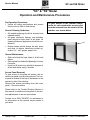
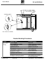
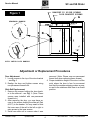
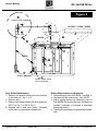
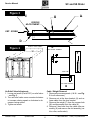
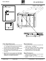
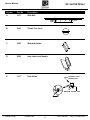
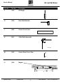
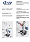
SC and SS Slider
Service Manual
SC and SS Slider
Click the Procedure to View
Operation and Maintenance Procedure
Door Is Not Closing
Door Adjustment
Slide Rail Replacement
Door Guide Replacement
Spring Replacement or Adjustment
Air Relief Valve Adjustment
Cable / Weight Removal
Cable / Weight Replacement
Magnet Adjustment
Magnet Replacement
Parts and Descriptions
Warranty Service Policy
Quikserv Corp.©
quikserv.com
2
3
4
4
5
5
6
6
7
7
7
8-9
10
• 1-800-388-8307 • Fax (713) 849-5708
SC and SS Slider
Service Manual
“SC” & “SS” Model
Operation and Maintenance Procedures
Pre-Operation Procedures:
• Unlock all locking mechanisms and ensure
that the door is free of obstructions.
To gain access to the internal components for each window the access panel
must be removed from the exterior of the
window - see arrows below.
General Cleaning Guidelines:
• All weather-stripping should be checked and
cleaned weekly.
• All glass, aluminum framing, and stainless
steel should be kept clean at all times. All
cleaning fluids and applicators should be nonabrasive.
• Bottom bases should always be kept clean
and clear of objects obstructing normal operation (i.e. - dirt, grease, paper, etc.).
General Maintenance:
• Slide rail should be kept clean of all dirt and
debris.
• Rails should be oiled with lightweight oil every
6 months.
• Hook lock & thumb turn should be cleaned of
all dirt and debris every 6 months.
Access Panel Removal:
To gain access to the slide rail system, the access cover panel must first be removed. The cover panel is located at the top of the header on the
operator’s side of the window.
Remove the screws protruding from the cover
panel. - See arrow below.
Please refer to the Trouble Shooting Section in
this manual for additional information on the window adjustments or service procedures.
Contact us at (800) 388-8307 for assistance or
for information on the nearest service center in
your area.
Quikserv Corp.©
quikserv.com
• 1-800-388-8307 • Fax (713) 849-5708
SC and SS Slider
Service Manual
BRACKET TO SLIDE SCREWS
DOOR BRACKET SCREWS
A
STANDARD HANDLE
DOOR BRACKET
SLIDE
DOOR JAMB
DOOR
C
B
DOOR JAMB
DOOR JAMB
DOOR
"A"
DOOR
S/S BASE
D
"A"
AUTO LATCH-LOCK HANDLE
Trouble Shooting Procedures
Trouble
Door is Not
Closing
Probable Cause
1. Door dragging
2. Unit installed out of square
3. Door obstructed
4. Defective slide rail
5. Door guide worn or bent
6. Spring broke - serial # 9,715 - 15,037
7. Air relief valve out of adjustment
serial # 9,715 - 15,037
8. Defective cable assembly
9. Weight stuck
10. Magnet in hold-open position
Quikserv Corp.©
quikserv.com
Probable Solution
Adjust door
Contact construction company
Remove obstruction
Replace or oil slide rail
See door guide replacement
Cable replacement
Remove obstruction
See cable diagram
Place magnet cap on magnet
and make adjustments
• 1-800-388-8307 • Fax (713) 849-5708
SC and SS Slider
Service Manual
BRACKET TO SLIDE SCREWS
DOOR BRACKET SCREWS
Figure 1
A
STANDARD HANDLE
SLIDE
DOOR BRACKET
DOOR JAMB
DOOR
C
B
DOOR JAMB
DOOR JAMB
DOOR
"A"
DOOR
S/S BASE
D
"A"
AUTO LATCH-LOCK HANDLE
Adjustment or Replacement Procedures
Door Adjustment:
1. Loosen screws in the top of the door bracket
- see Fig. 1
2. Realign the door and tighten screws using
non-permanent thread-lock.
removed. (Note: Please use non-permanent
thread-lock when replacing these screws)
4. Proper installation height of the door is at the
point where the door is free for movement
and that the weather-stripping makes a proper seal to the stainless steel base in a closed
position.
Slide Rail Replacement:
1. Remove the screws holding the door bracket to the slide rail - see Fig. 1 (Note: These
screws were installed with non-permanent
thread-lock.)
2. After removing the door, you now have access to the screws holding the slide rail (Part
#1917) to the header. You may need to slide
the inner race of the rail to the left or right to
gain access to the inner screws.
3. Install new slide rail in reverse order it was
Quikserv Corp.©
quikserv.com
• 1-800-388-8307 • Fax (713) 849-5708
SC and SS Slider
Service Manual
Figure 2
K
CABLE ROLLER ASSEMBLY
ACCESS COVER PANEL
DOOR CABLE BRACKET
H
SIDE VIEW
A
CABLE
K
J
HEADER
F
SIDE JAMB
O
DOOR
B
D
CENTER JAMB
CABLE
SIDE JAMB
DOOR
S/S BASE
DOOR WEIGHT
M
ACCESS COVER PLATE
FOR DOOR WEIGHT
Door Guide Replacement:
1. Remove the screws holding the door bracket
to the slide rail - Fig. 1 or 2.
2. Remove door.
3. Remove the screw holding the door guide pin
#1017 on Fig. 1 or #1014 Fig. 2.
4. Replace with a new door guide - Reinstall
screw with non-permanent thread-lock.
Quikserv Corp.©
quikserv.com
Spring Replacement or Adjustment:
1. Remove spring from Part #5208 - see Fig. 3.
2. Replace with the new spring - Part #1029.
3. Adjust spring tension by loosening nuts on
Part #5208 and turning the nuts clockwise or
counter- clockwise to increase or decrease
the spring tension.
4. Tighten nuts and apply non-permanent threadlock.
• 1-800-388-8307 • Fax (713) 849-5708
SC and SS Slider
Service Manual
Figure 3
C
A
E
SPRING
ADJUSTMENT
SET SCREW
D
K
ACCESS COVER PANEL
Figure 2
CABLE ROLLER ASSEMBLY
J
F
HEADER
SIDE JAMB
DOOR
CENTER JAMB
SIDE JAMB
DOOR
SIDE VIEW
S/S BASE
M
DOOR CABLE BRACKET
H
Air Relief Valve Adjustment:
1. Loosen set screw (Part #1037) on relief valve
- see Fig. 3.
2. Turn air relief valve screw counter-clockwise
to increase closing speed or clockwise to decrease closing speed.
3. Tighten set screw.
Quikserv Corp.©
quikserv.com
Cable / Weight Removal:
1. Remove the access panels (J & M – see Fig.
2 for all references).
2. Remove nut at the door bracket (H) and release cable from the door bracket.
3. Remove the weight (F) from the access hole
(M) and disconnect from the cable (K).
4. Remove 2 hex bolts from the cable roller assembly (K) and remove the old assembly (cable, roller, and bracket).
• 1-800-388-8307 • Fax (713) 849-5708
SC and SS Slider
Service Manual
ACCESS COVER PANEL
K
CABLE ROLLER ASSEMBLY
J
HEADER
SIDE JAMB
DOOR
CENTER JAMB
SIDE VIEW
SIDE JAMB
DOOR
AC
S/S BASE
DOOR CABLE BRACKET
H
M
HEADER
Cable / Weight Replacement:
1. Drop cable in the guide sleeve at the side jamb
(K – see Fig. 2 for all references) and retrieve
at access hole (M). Reconnect weight.
2. Securely reconnect cable roller assembly with
two hex bolts to the side jamb at (K).
3. Reconnect cable to the door bracket with hex
nut at (H).
4. Reinstall both access panels (J) & (M). Note:
Make sure non-permanent thread lock is
applied to the weight lug threads.
Quikserv Corp.©
quikserv.com
DOOR
CENTER JAMB
SIDE JAMB
DOOR
Magnet Adjustment:
1. Loosen the 8-32 nut on the door bracket holding the magnet – see Fig. 2
2. Adjust by turning the screw either clockwise
or counter clockwise until the magnet is adjusted properly to hold the door open.
3. Tighten the 8-32 nut onto the bracket.
Magnet Replacement:
S/S BASE
1. Using a slotted screwdriver, loosen the screw
holding the magnet in place.
2. Replace magnet part #1054 and tighten
screw.
M
• 1-800-388-8307 • Fax (713) 849-5708
SC and SS Slider
Service Manual
Key No.
Part No.
Description
A
1917
Slide Rail
B
2022
Thumb Turn Lock
C
3588
Standard Handle
D
5586
Auto Latch-Lock Handle
E
1017
Door Guide
BOTTOM DOOR
EXTRUSION
BOTTOM GUIDE PIN
E
Quikserv Corp.©
quikserv.com
• 1-800-388-8307 • Fax (713) 849-5708
SC and SS Slider
Service Manual
Key No.
Part No.
Description
F
1035
SC Weight
H
3518
Door Cable Bracket
DOOR CABLE BRACKET
J
3606
JH
Access Cover Panel
ACCESSK COVER PANEL
CABLE ROLLER ASSEMBLY
K
5601
Cable Roller Assembly
AC
SIDE VIEW
M
3535
Access Panel Cover Plate
O
1054
Magnet
HEADER
quikserv.com
DOOR
ENTER JAMB
Quikserv Corp.©
SIDE JAMB
DOOR
• 1-800-388-8307 • Fax (713) 849-5708
SC and SS Slider
Service Manual
Warranty Service Policy
1. Quikserv Corp. MUST be notified of a warranty situation before any work is performed.
Otherwise, Quikserv Corp will not be responsible to pay for unauthorized work.
7. Quikserv Corp. needs to be notified of any extra parts - either to be sent back or to be kept
by the service technician. Any parts that were
replaced must be returned to Quikserv Corp.
if required verbally or on the service work order copy supplied with the parts sent by Quikserv Corp. If the parts are not returned, the
part cost + mark up will be deducted from the
service invoice.
2. Quikserv Corp. requires the following on each
invoice submitted: an itemized account of work
performed detailing hours charged and parts
used, along with a short detailed description
of the problem noted.
8. A purchase order number will be given either
verbally or on the service work order from
Quikserv Corp. Please use this on all invoicing.
3. Quikserv Corp. will authorize a set dollar
amount to be invoiced prior to performing services that will be rendered. This amount will
be determined from the initial call to the service company as a fair maximum. If additional
amounts are to be invoiced, they must be discussed with Quikserv Corp. prior to invoicing.
9. Work required on a window unit not covered
under Quikserv’s warranty must be reported
to Quikserv Corp. before work is begun.
4. A service technician on a warranty service call
needs to call our customer service department
at (800) 388-8307 or (713) 849-5882 before
leaving the job site.
10.Quikserv’s payment terms are net 30. The information above will help us assure the fastest and most efficient service possible. For
further information or if you have any questions, please do not hesitate to contact us at
(800) 388-8307.
5. A service company representative needs to
call the store where the work is to be performed prior to going to that store. Set up a
date and approximate time of arrival and if it
is foreseen that the agreed upon time cannot
be met, contact the store and make other arrangements.
Customer Service Department
6. Warranty parts sent to service companies are
parts previously decided on that should cover
the necessary repairs. Additional parts will be
sent upon notification to Quikserv Corp.
Quikserv Corp.©
quikserv.com
10
• 1-800-388-8307 • Fax (713) 849-5708