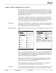
1
System User Manual
AKC 55 Rack Controller
This User’s Manual contains installation, start-up, and operating instructions for all parts of the Danfoss AKCESS System. Use the Table of
Contents to find the section you need right now. You’ll probably find it
useful later to browse through the entire manual.
Additional copies are available from your Danfoss Representative or from
the Danfoss Automatic Controls Literature Department.
At Danfoss, continuous improvement to documentation goes hand-in-hand with the
product refinement and quality for which Danfoss is world famous. We welcome
your suggestions for additions or improvements to any of our manuals or other
literature. Please address your comments to:
DANFOSS Inc.
Literature Department
7941 Corporate Drive
Baltimore, MD 21236
Telephone:(410) 931-8250
FAX:(410) 931-8256
Copyright © 1999, 2003, 2004 Danfoss Inc.
AKCESS
System Manual
RC.IU.B2.22
02/2004
TOC - 1
TOC - 2
System Manual
RC.IU.B2.22
02/2004
AKCESS
Contents
CHAPTER 1
Introduction
Overview of the AKCESS Network ................................................................................................................................... 1-1
System Capacities
....................................................................................................................................................... 1-2
System Components ....................................................................................................................................................... 1-4
AKA 65 Network Supervisor Software ...................................................................................................................... 1-4
AKC 55 Controller ...................................................................................................................................................... 1-4
Input and Output Boards ........................................................................................................................................... 1-5
RO8 Relay Output Board ............................................................................................................................................ 1-5
RO8S Relay Output Board with Override Switches .................................................................................................. 1-5
OI8 & OIL8 On-Off Input Boards ............................................................................................................................... 1-5
SI8 Sensor Input Board .............................................................................................................................................. 1-6
VO2 Variable Output Board ........................................................................................................................................ 1-6
OVR Override Box ....................................................................................................................................................... 1-7
OAB-1 Office Alarm Box ............................................................................................................................................ 1-7
AKC 164 Smart Case Controllers ............................................................................................................................... 1-8
CHAPTER 2
Control Network Layout
Overview of the Host Network .......................................................................................................................................... 2-1
Overview of the I/O Network ............................................................................................................................................. 2-2
CHAPTER 3
Chapter 3 - 1
Installing and Setting Up the Components
Installing an AKC 55 Controller ................................................................................ 3-1 to 3-9
AKC 55 with Enclosure ......................................................................................................................................... 3-1 to 3-5
Mounting
....................................................................................................................................................... 3-1
AKC 55 Addressing ................................................................................................................................................... 3-2
CPU Battery Enable .................................................................................................................................................... 3-2
Modem Installation ..................................................................................................................................................... 3-3
Telephone Line Installation ........................................................................................................................................ 3-3
Ethernet Adapter Connection .................................................................................................................................... 3-3
Host Network Cabling & Termination ........................................................................................................................ 3-4
I/O Network Cabling & Termination .......................................................................................................................... 3-5
Power Wiring
....................................................................................................................................................... 3-5
AKC 55 Installer Final Inspection .............................................................................................................................. 3-6
AKC 55 Panel Mount ......................................................................................................................................... 3-7 to 3-11
Mounting
....................................................................................................................................................... 3-7
AKC 55 Addressing ................................................................................................................................................... 3-7
CPU Battery Enable ............................................................................................................................................. 3-7, 3-8
Modem Installation ..................................................................................................................................................... 3-8
Telephone Line Installation ........................................................................................................................................ 3-8
Ethernet Adapter Connection .................................................................................................................................... 3-8
Host Network Cabling & Termination ........................................................................................................................ 3-9
I/O Network Cabling & Termination ........................................................................................................................ 3-10
Power Wiring
..................................................................................................................................................... 3-10
AKC 55 Installer Final Inspection ............................................................................................................................ 3-11
AKCESS
System Manual
RC.IU.B2.22
02/2004
TOC - 3
Contents (continued)
Chapter 3 - 2
Installing I/O Network Boards:
Power Supplies, Enclosures, and Alternative Mounting ..................................... 3-12, 3-13
Load Factors and Power Supplies ................................................................................................................................... 3-12
The IOPS Power Supply ................................................................................................................................................... 3-12
The IOPS2 Power Supply ................................................................................................................................................. 3-13
The IOPSWM Power Supply ........................................................................................................................................... 3-13
IO4R and IO12 Enclosures .............................................................................................................................................. 3-13
Aternative Mounting for I/O Boards .............................................................................................................................. 3-13
Chapter 3 - 3
Installing RO8 and RO8S Relay Output Boards .................................................. 3-14 to 3-16
RO8 and RO8S
RO8 and RO8S
RO8 and RO8S
RO8 and RO8S
RO8 and RO8S
RO8 and RO8S
Inspection of the
Chapter 3 - 4
Description and Identification ............................................................................................................. 3-14
Mounting .............................................................................................................................................. 3-14
Addressing ........................................................................................................................................... 3-15
Network Connections ........................................................................................................................... 3-15
Controlled Load Connections .............................................................................................................. 3-16
Power Connections ............................................................................................................................... 3-16
Installed RO8 or RO8S ........................................................................................................................ 3-16
Installing OI8 and OIL8 On-Off Input Boards ....................................................... 3-17 to 3-19
OI8 and OIL8 Description and Identification ................................................................................................................ 3-17
OI8 and OIL8 Mounting ................................................................................................................................................. 3-17
OI8 and OIL8 Addressing ..................................................................................................................................... 3-17, 3-18
OI8 and OIL8 Network Connections ............................................................................................................................. 3-18
OI8 and OIL8 Monitored Load Connections ................................................................................................................ 3-18
OI8 and OIL8 Power Connections ................................................................................................................................. 3-19
Inspection of the Installed OI8 or OIL8 ........................................................................................................................... 3-19
Chapter 3 - 5
Installing SI8 Sensor Input Boards ...................................................................... 3-20 to 3-24
SI8 Description and Identification ................................................................................................................................. 3-20
SI8 Mounting
..................................................................................................................................................... 3-20
SI8 Addressing
..................................................................................................................................................... 3-20
SI8 Network Connections .............................................................................................................................................. 3-21
SI8 Sensor Connections ................................................................................................................................................. 3-21
Setting Up and Connecting Compressor Current Sensors .................................................................................... 3-21, 3-22
SI8 Sensors: Types of Sensors ...................................................................................................................................... 3-23
Sensors from Other Manufacturers ................................................................................................................................. 3-24
SI8 Power Connections .................................................................................................................................................. 3-24
Inspection of the Installed SI8 ......................................................................................................................................... 3-24
Chapter 3 - 6
Installing VO2 Analog Output Boards .................................................................. 3-25 to 3-27
VO2 Description and Identification ............................................................................................................................... 3-25
VO2 Mounting
..................................................................................................................................................... 3-25
VO2 Addressing
..................................................................................................................................................... 3-25
VO2 Network Connections ............................................................................................................................................ 3-26
VO2 Controlled Load Connections ................................................................................................................................ 3-26
VO2 Power Connections ................................................................................................................................................ 3-26
Inspection of the Installed VO2 ....................................................................................................................................... 3-27
TOC - 4
System Manual
RC.IU.B2.22
02/2004
AKCESS
Contents (continued)
Chapter 3 - 7
Installing RTC Rooftop Controllers ...................................................................... 3-28 to 3-31
RTC Description
..................................................................................................................................................... 3-28
RTC Capabilities and Capactiies ............................................................................................................................ 3-28, 3-29
RTC Mounting
..................................................................................................................................................... 3-29
RTC Addressing
..................................................................................................................................................... 3-29
RTC Network Connections .............................................................................................................................................. 3-30
RTC Sensor Connections ................................................................................................................................................. 3-30
RTC On/Off Input Connections ....................................................................................................................................... 3-31
RTC Relay Output Connections ...................................................................................................................................... 3-31
RTC Power Connections .................................................................................................................................................. 3-31
Inspection of the Installed RTC ....................................................................................................................................... 3-31
Chapter 3 - 8
Installing AKC 164SC Smart Case Controllers .................................................... 3-32 to 3-42
AKC 164 SC Description and Identification .................................................................................................................. 3-32
AKC 164 SC Mounting ................................................................................................................................................... 3-32
AKC 164 SC Addressing ................................................................................................................................................ 3-33
AKC 164 SC Network Connections ................................................................................................................................ 3-33
AKC 164 SC Sensor Connections .................................................................................................................................. 3-34
AKC 164 SC Temperature Sensor Mounting Locations, Liquid Side Control .............................................................. 3-35
AKC 164 SC Drain Sensor Location and Mounting ...................................................................................................... 3-36
AKC 164 SC AKV 10 and AKV 15 Valve Connection ................................................................................................... 3-36
AKC 164 SC Temperature Sensor Mounting Locations, Suction Side Control ........................................................... 3-37
AKC 164 SC Power Module (PM 164) Connection ....................................................................................................... 3-38
AKC 164 SC Controlled Load Connections (Lights, Fans, and Anti-sweats) .............................................................. 3-38
AKC 164 SC Defrost Module (DF 164) Connection ...................................................................................................... 3-39
AKC 164 SC Controlled Load Connections (Defrost) ................................................................................................... 3-39
AKC 164 SC Typical Connection Diagram ..................................................................................................................... 3-40
AKC 164 SC KVQ Electronic Evaporator Pressure Regulating Valve Connections ..................................................... 3-41
AKC 164 SC Multi-Purpose Input Connections ............................................................................................................ 3-41
AKC 164 SC Power Connections .................................................................................................................................... 3-42
Inspection of the Installed AKC 164 SC ......................................................................................................................... 3-42
Chapter 3 - 9
Installing an OVR Override Box ........................................................................... 3-43 to 3-45
OVR Description and Identification .............................................................................................................................. 3-43
OVR Mounting
..................................................................................................................................................... 3-43
OVR Addressing
..................................................................................................................................................... 3-44
OVR Network Connections ............................................................................................................................................ 3-44
OVR Power Connections ............................................................................................................................................... 3-44
Inspection of the Installed OVR ...................................................................................................................................... 3-45
Chapter 3 - 10 Installing an OAB-1 Office Alarm Box ................................................................... 3-46, 3-47
OAB-1 Description and Identification ........................................................................................................................... 3-46
OAB-1 Mounting
..................................................................................................................................................... 3-46
OAB-1 Network and Power Connections ...................................................................................................................... 3-47
Inspection of the Installed OAB-1 .................................................................................................................................. 3-47
AKCESS
System Manual
RC.IU.B2.22
02/2004
TOC - 5
Contents (continued)
CHAPTER 4
Initial Configuration of an AKC 55
Introduction to Configuration ........................................................................................................................................... 4-1
Check battery
....................................................................................................................................................... 4-1
Authorization codes ....................................................................................................................................................... 4-1
Selection of Units and Languages .................................................................................................................................... 4-2
Chapter 4 - 1
Configuring Refrigeration ...................................................................................... 4-3 to 4-21
Starting with a Partially Configured AKC 55 .................................................................................................................... 4-3
Starting with a Completely Un-configured AKC 55 .......................................................................................................... 4-4
Navigation and making changes, entering numerals, entering labels ............................................................................. 4-4
Constrained fields
....................................................................................................................................................... 4-4
Selecting from list boxes .................................................................................................................................................... 4-5
Rack Info configuration ......................................................................................................................................... 4-5 to 4-6
Adding a rack
....................................................................................................................................................... 4-4
Suction Info Configuration .................................................................................................................................... 4-6 to 4-9
Two-stage systems and de-superheaters ..................................................................................................... 4-9 to 4-10
Compressor Configuration ................................................................................................................................. 4-10 to 4-15
Additional compressors in a suction group ............................................................................................................ 4-12
Compressor oil and safety information .................................................................................................................... 4-12
Neutral Zone control .................................................................................................................................... 4-13 to 4-14
Compressor capacity staging patterns .................................................................................................................... 4-14
Evaporator configuration .................................................................................................................................... 4-15 to 4-24
Case lights button (Case lights override) .................................................................................................... 4-16 to 4-17
AKC 55 subcooling circuits ......................................................................................................................... 4-17 to 4-18
AKC 55 refrigeration circuits ........................................................................................................................ 4-18 to 4-21
Defrost
......................................................................................................................................... 4-22 to 4-23
Shutdown schedules ................................................................................................................................................ 4-23
Evaporator alarms ......................................................................................................................................... 4-23 to 4-24
Condenser configuration .................................................................................................................................... 4-24 to 4-36
Aircooled condensers .................................................................................................................................. 4-25 to 4-31
Split condensers .................................................................................................................................... 4-29 to 4-30
Reaction zone and time ...................................................................................................................................... 4-30
Enviroguard systems ............................................................................................................................. 4-30 to 4-31
Evaporative condensers ............................................................................................................................... 4-31 to 4-36
Pump, louver, and sump settings ...................................................................................................................... 4-34
Inverter settings; freeze protection; dump valve ................................................................................. 4-34 to 4-36
Receiver configuration ....................................................................................................................................... 4-36 to 4-37
Heat reclaim configuration ................................................................................................................................. 4-37 to 4-38
Alarms configuration for refrigeration ............................................................................................................ 4-38 to 4-40
Alarm levels
..................................................................................................................................................... 4-39
What You Can Change in a Standard Alarm ............................................................................................................ 4-39
System alarms
..................................................................................................................................................... 4-40
Board & Points configuration ........................................................................................................................... 4-40 to 4-51
Relay Outputs (DIGITAL OUTPUTS) .......................................................................................................... 4-40 to 4-41
Sensor Inputs (ANALOG INPUTS) ............................................................................................................. 4-41 to 4-43
On-off Inputs (DIGITAL INPUTS) ............................................................................................................... 4-43 to 4-44
Variable Outputs (ANALOG OUTPUTS) ................................................................................................................. 4-45
TOC - 6
System Manual
RC.IU.B2.22
02/2004
AKCESS
Contents (continued)
Board & Points configuration (continued) ..................................................................................................... 4-40 to 4-51
Other controllers (AKC 16x, EKC, DegreeMaster, VLT and AKD drives, DCU ......................................... 4-45 to 4-51
AKC 16x circuit board & points .............................................................................................................. 4-46, 4-47
Network re-scan and initialization ............................................................................................................. 4-47
Navigation ..................................................................................................................................................... 4-47
EKC circuits board & points ................................................................................................................. 4-47 to 4-49
Network re-scan and initialization ............................................................................................................. 4-48
Wink (EKC) ................................................................................................................................................ 4-49
Degree Master board & points ................................................................................................................ 4-49, 4-50
Locate procedure ....................................................................................................................................... 4-50
Activating the service pin from the display ............................................................................................. 4-50
Initialization ................................................................................................................................................ 4-50
Wink (Degree Master) ............................................................................................................................... 4-50
VLT and AKD drives board & points .......................................................................................................... 4-4, 4-5
DCU circuits board & points (SECTION TO BE ADDED) ............................................................................... 4-51
Chapter 4 - 2
Configuring HVAC ................................................................................................. 4-52 to 4-97
Introduction to HVAC Configuration ..................................................................................................................... 4-52, 4-53
RTU Configuration
......................................................................................................................................... 4-53 to 4-64
RTU fan configuration ..................................................................................................................................... 4-53, 4-55
RTU cooling configuration ........................................................................................................................... 4-55 to 4-57
RTU heating configuration ........................................................................................................................... 4-57 to 4-61
Analog valve strategy ..................................................................................................................................... 4-60, 4-61
RTU dehumidification configuration ........................................................................................................... 4-61 to 4-63
RTU air damper configuration ......................................................................................................................... 4-63, 4-64
RTU alarms configuration ......................................................................................................................................... 4-64
RTU board & points ................................................................................................................................................. 4-64
AHU Configuration ......................................................................................................................................... 4-65 to 4-69
AHU fan configuration ................................................................................................................................. 4-65 to 4-67
AHU outside air coil configuration .............................................................................................................. 4-67 to 4-69
RTC Configuration
......................................................................................................................................... 4-69 to 4-82
RTC fan configuration .................................................................................................................................. 4-69 to 4-71
RTC cooling configuration ........................................................................................................................... 4-71 to 4-72
RTC dehumidification configuration ............................................................................................................... 4-74, 4-75
RTC air damper configuration ...................................................................................................................... 4-75 to 4-77
RTC schedules
..................................................................................................................................................... 4-77
RTC alarm configuration ........................................................................................................................................... 4-77
RTC I/O points configuration ....................................................................................................................... 4-77 to 4-82
Configuring RTC relay outputs (RTC DIGITAL OUTPUTS) ........................................................................... 4-78
Configuring RTC sensor inputs (RTC ANALOG INPUTS) .................................................................. 4-78 to 4-79
Configuring RTC on-off inputs (RTC DIGITAL INPUTS) .................................................................... 4-79 to 4-80
Configuring RTC variable outputs (RTC ANALOG OUTPUTS) ......................................................... 4-80 to 4-81
RTC address and init ................................................................................................................................ 4-81, 4-82
ClimaTECH configuration .................................................................................................................................... 4-82 to 4-91
ClimaTECH fan configuration ......................................................................................................................... 4-83, 4-84
ClimaTECH cooling configuration ........................................................................................................................... 4-84
ClimaTECH heating configuration ............................................................................................................... 4-84 to 4-86
ClimaTECH dehumidification configuration ............................................................................................................ 4-86
ClimaTECH economizer configuration ..................................................................................................................... 4-87
ClimaTECH alarm configuration ............................................................................................................................... 4-87
ClimaTECH schedule configuration ......................................................................................................................... 4-88
ClimaTECH I/O configuration ...................................................................................................................... 4-88 to 4-90
ClimaTECH relay output configuration (ClimaTECH DIGITAL OUTPUTS) ................................................... 4-88
AKCESS
System Manual
RC.IU.B2.22
02/2004
TOC - 7
Contents (continued)
ClimaTECH sensor input configuration (ClimaTECH ANALOG INPUTS) ..................................................... 4-89
ClimaTECH on-off input configuration (ClimaTECH DIGITAL INPUTS) ....................................................... 4-90
ClimaTECH address and init ................................................................................................................... 4-90 , 4-91
Uploading to the AKC 55 .................................................................................................................................. 4-91
Seasons Smart Coil HVAC unit configuration ..................................................................................................... 4-91 to 4-97
Beginning configuration .............................................................................................................................. 4-91 to 4-92
SC4 cooling configuration ............................................................................................................................... 4-93, 4-94
SC4 heating configuration ............................................................................................................................... 4-94, 4-95
SC4 dehumidification configuration ................................................................................................................ 496, 4-97
SC4 condenser configuration .......................................................................................................................................... 4-97
SC4 alarms configuration ................................................................................................................................................. 4-97
SC4 board & points configuration .................................................................................................................................. 4-97
Chapter 4 - 3
Configuring Lighting ........................................................................................... 4-97 to 4-102
Introduction to lighting configuration ................................................................................................................... 4-97, 4-98
AKC 55 lighting zone setup ............................................................................................................................... 4-98 to 4-101
Lighting board & points configuration ......................................................................................................................... 4-101
Powerlink (R) configuration ........................................................................................................................................... 4-101
Cutler-Hammer configuration ........................................................................................................................................ 4-101
Powerlink and Cutler-Hammer board & point configuration ............................................................................. 4-101, 4-102
Locate procedure ................................................................................................................................................... 4-102
Chapter 4 - 4
Energy Meter Configuration ............................................................................. 4-102 to 4-108
Installation
................................................................................................................................................... 4-102
Configuration
..................................................................................................................................... 4-102 to 4-108
Soft starts
................................................................................................................................................... 4-106
Demand limiting ..................................................................................................................................... 4-106 to 4-108
HVAC demand limiting ..................................................................................................................................... 4-107
Lighting demand limiting ................................................................................................................................. 4-108
How demand limiting works ............................................................................................................................ 4-108
Chapter 4 - 5
Configuring Alarms ........................................................................................... 4-108 to 4-127
Configure Alarms Menu ...................................................................................................................................... 4-108, 4-109
Configuring Refrigeration Alarms .................................................................................................................... 4-109 to 4-122
Alarms suspended .................................................................................................................................................. 4-111
Suspending rack alarms .......................................................................................................................................... 4-111
Configuring alarm settings ......................................................................................................................... 4-112 , 4-113
Analog alarms
........................................................................................................................................ 4-113, 4-114
Field limits and units ........................................................................................................................................ 4-114
Disabling
................................................................................................................................................... 4-114
What alarms are needed ......................................................................................................................................... 4-114
Frequently Asked Questions ...................................................................................................................... 4-114, 4-115
Types of suction alarms, listed .............................................................................................................................. 4-115
Compressor alarms ...................................................................................................................................... 4-115, 4-116
Circuit alarms
.................................................................................................................................... 4-116, to 4-119
AKC 55 circuits ..................................................................................................................................... 4-117, 4-118
AKC 164 alarms .................................................................................................................................... 4-118, 4-119
EKC, DCU, Degree Master, and AKC 165 Subcooling Controller alarms ..................................................... 4-119
Condenser alarms ................................................................................................................................................... 4-120
“Other” rack alarms ...................................................................................................................................... 4-121, 4-122
Bitzer rack alarms ............................................................................................................................................. 4-122
HVAC Alarms
..................................................................................................................................... 4-122 to 4-125
TOC - 8
System Manual
RC.IU.B2.22
02/2004
AKCESS
Contents (continued)
AHU, RTU, and SC4 alarms .................................................................................................................................... 4-123
RTC alarms
................................................................................................................................................... 4-124
ClimaTECH alarms ....................................................................................................................................... 4-124, 4-125
Miscellaneous alarms ..................................................................................................................................... 4-125 to 4-127
Example miscellaneous alarm ....................................................................................................................... 4-126, 4-127
Chapter 4 - 6
Miscellaneous Points Configuration ................................................................ 4-128 to 4-140
Introduction
................................................................................................................................................... 4-128
Starting Configuration ................................................................................................................................................... 4-128
Plan Strategy First
................................................................................................................................................... 4-128
Miscellaneous relay outputs (DIGITAL OUTPUTS) ........................................................................................ 4-128 , 4-129
Miscellaneous sensor inputs (ANALOG INPUTS) ...................................................................................................... 4-129
Miscellaneous on-off inputs (DIGITAL INPUTS) ........................................................................................................ 4-129
Specifying miscellaneous conversions .............................................................................................................. 4-129, 4-130
Miscellaneous calculations ........................................................................................................................................... 4-130
Point creation
..................................................................................................................................... 4-130 to 4-132
Custom Strategy example ................................................................................................................................. 4-132 to 4-140
Creating the miscellaneous points sensor inputs ..................................................................................... 4-132 , 4-133
Writing the custom strategy .................................................................................................................... 4-133 to 4-137
Data definitions ................................................................................................................................ 4-133 to 4-135
The rules area ..................................................................................................................................... 4-136 to 4-138
Writing rules ........................................................................................................................................ 4-136, 4-137
Creating the miscellaneous points relay output ...................................................................................... 4-138 to 4-140
Units
................................................................................................................................................... 4-140
Style
................................................................................................................................................... 4-140
Undo, Cancel, Redo ......................................................................................................................................... 4-140
CHAPTER 5
Using the System
Introduction; Authorization ......................................................................................................................... 5-1
Getting Authorized to Make Changes ........................................................................................................ 5-1
Chapter 5 - 1 Navigation and Making Changes ............................................................... 5-3 to 5-8
Introduction
......................................................................................................................... 5-1 to 5-5
Getting Back to the Icon Menu .................................................................................................................. 5-6
Viewing and Changing Settings .................................................................................................................. 5-6
Changing Numeric Values .......................................................................................................................... 5-7
Changing List Fields
.................................................................................................................................... 5-7
Changing the From and To Times .............................................................................................................. 5-7
Changing the Days of the Week and Holidays .......................................................................................... 5-7
Changing Name Fields ............................................................................................................................... 5-8
Chapter 5 - 2 Using the Service Screens ...................................................................... 5-9 to 5-11
Introduction
.................................................................................................................................... 5-9
Auto/Manual Relays ......................................................................................................................... 5-9, 5-10
Sensor Adjustment .................................................................................................................................. 5-10
Maintenance Hours .................................................................................................................................. 5-11
Bd/Pt Locations
.................................................................................................................................. 5-11
Chapter 5 - 3 Using the Smart Case Controller Screens ........................................... 5-12 to 5-17
AKC 16x Status Screen Fields and Terms ................................................................................. 5-12 to 5-14
Evaporator Settings Screen ...................................................................................................................... 5-15
AKCESS
System Manual
RC.IU.B2.22
02/2004
TOC - 9
Contents (continued)
Evaporator Schedules ............................................................................................................................... 5-15
Evaporator Service Screens ................................................................................................................. 5-16 to
Service: Manual Operation .............................................................................................................. 5-16, 5-17
Service: AKC 16x Shutdown ................................................................................................................... 5-17
Service: Case Cleaning ............................................................................................................................ 5-17
Chapter 5 - 4 Using the Refrigeration Screens for Refrigeration Circuits
Controlled Directly from AKC 55’s ............................................................ 5-18, 5-19
Evaporator Status Screen ......................................................................................................................... 5-18
Evaporator Settings Screen ............................................................................................................. 5-18, 5-19
Evaporator Schedules, Alarms, and Service Screens ............................................................................... 5-19
Chapter 5 - 5 Using the Communications Screens ..................................................... 5-20 to 5-27
Introduction
.................................................................................................................................. 5-20
Host Network Screen .............................................................................................................................. 5-20
I/O Network Status Menu ....................................................................................................................... 5-20
Status Screens (for each type of I/O board) ............................................................................................ 5-21
IP Network (Ethernet) ................................................................................................................. 5-21 to 5-23
IP Network Status Screen .............................................................................................................. 5-21, 5-22
Alarm Routing for Ethernet ............................................................................................................. 5-22, 5-23
Printer Settings Screens ........................................................................................................................... 5-24
Modem Status Screen ..................................................................................................................... 5-25, 5-26
Messages
.................................................................................................................................. 5-27
Chapter 5 - 6 Using the History Screens (for History Retrieval) ............................... 5-28 to 5-32
Introduction
.................................................................................................................................. 5-28
Selecting Points to View .......................................................................................................................... 5-29
History Stats .........................................................................................................................................
5-31, 5-32
Chapter 5 - 7 Using the Miscellaneous Points Screens ............................................... 5-33, 5-34
Relay Output Status ........................................................................................................................ 5-33, 5-34
Chapter 5 - 8 Using the Alarms Screens ...................................................................... 5-35 to 5-38
The Alarms Menu .................................................................................................................................. 5-35
The Active Alarms Screen ....................................................................................................................... 5-36
The Cleared Alarms Screen ..................................................................................................................... 5-37
The Alarm Status Screen ......................................................................................................................... 5-37
The Network Alarms Screen ................................................................................................................... 5-37
The Alarm Service Screen ....................................................................................................................... 5-38
Chapter 5 - 9 Overrides .................................................................................................... 5-39, 5-40
Overrides Using Service Screens ............................................................................................................ 5-39
Overriding Sensor Values ......................................................................................................................... 5-40
Overriding Using RO8S Switches ............................................................................................................ 5-40
Overrides Using the Manager’s Override Box ........................................................................................ 5-40
Keyswitch Override for Refrigeration High Temperature Alarms .......................................................... 5-40
TOC - 10
System Manual
RC.IU.B2.22
02/2004
AKCESS
Contents (continued)
CHAPTER 6
Configuring and Using Non-AKCESS Nodes
Introduction
.................................................................................................................................... 6-1
Chapter 6-1 Echelon-capable Utility Meters ............................................................................ 6-1
Installation
.................................................................................................................................... 6-1
Configuration
............................................................................................................................. 6-1, 6-2
Using Utility Meter Status Screens ..................................................................................................... 6-2, 6-3
History for Utility Meters ................................................................................................................ 6-3 to 6-5
Demand Limiting ......................................................................................................................... 6-5 to 6-8
How Demand Limiting Works ................................................................................................................... 6-8
Chapter 6 - 2 Bitzer Screw Compressor Echelon Interface ........................................ 6-9 to 6-12
Bitzer Configuration .......................................................................................................................... 6-9, 6-10
Compressor Status and Bitzer Status ....................................................................................................... 5-40
Alarms
......................................................................................................................... 6-11, 6-12
Resetting Shutdowns with the Bitzer Reset RO ...................................................................................... 6-12
Chapter 6 - 3 VLT® Electronic Drives ........................................................................... 6-13 to 6-17
VLT® Configuration for Compressors ..................................................................................................... 6-13
VLT® Resets, Proof, and Faults ............................................................................................................... 6-13
Continuing Configuration .............................................................................................................. 6-13 to 6-15
VLT® Status Screens for Compressors ................................................................................................... 6-15
Inverter Status
...................................................................................................................... 6-15 to 6-17
VLT®’s and Air-Cooled Condensers ........................................................................................................ 6-17
VLT®’s and Air Handler Motors .............................................................................................................. 6-17
Chapter 6 - 3 Square D Powerlink® Circuit Breaker Panels .................................................. 6-18
Powerlink® Configuration ................................................................................................................ 6-18, 6-19
Continuing Configuration .............................................................................................................. 6-19 to 6-21
Lighting Status for Zones with Powerlink® Panels .................................................................................. 6-15
APPENDIX A
Dimensions and Specifications
Physical Dimensions, Operating Environmental Limits, and Electrical Specifications for each component.
ENCLOSED:
User Manual for AK2 (Second Generation ADAP-KOOL®) Input and Output Modules
AKCESS
System Manual
RC.IU.B2.22
02/2004
TOC - 11