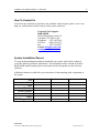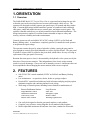
1
Installation and Operations Manual — Model VP2 Series Model VP2 Vertical Pivot Gate INSTALLATION AND OPERATIONS MANUAL B&B ARMR Corporate Office & Tech Support: 2009 Chenault Drive Suite 114 Carrollton, Tx 75006 Phone: (800) 367-0387 Fax: (972) 385-9887 E-mail: [email protected] [email protected] www.bb-armr.com MADE IN THE USA B&B ARMR A Division of B&B Roadway and Security Solutions 0066-9001 Rev A2 ii Installation and Operations Manual — Model VP2 INTRODUCTION Welcome! Congratulations on your purchase of a B&B ARMR Vertical Pivot Gate. In addition to providing detailed operating instructions, this manual describes how to install, maintain, and troubleshoot your vehicle gate. If you require additional assistance with any aspect of your vehicle barrier's installation or operation, please contact us. With years of experience in all aspects of perimeter security and related disciplines, our products are used throughout the world to control access and to protect people, equipment, and facilities. We offer a broad range of vehicle barrier and related security services: Turnkey installations Routine barrier preventative maintenance or emergency repairs (including work on non-B&B ARMR products) Spare or replacement parts Equipment upgrades (modernize your old equipment with state-of-the-art hydraulics and control systems) Ancillary security equipment such as security guard enclosures, card readers, security lighting, and many other security related products. Technical support via telephone and on site support with advanced scheduling. Safety SYMBOL MEANING: The lightning flash with arrowhead symbol, within an equilateral triangle, is intended to alert the user to the presence of non-insulated "dangerous voltage" within the product's enclosure that may be of sufficient magnitude to constitute a risk of electric shock to persons. B&B ARMR A Division of B&B Roadway and Security Solutions 0066-9001 Rev A2 iii Installation and Operations Manual — Model VP2 The exclamation point within an equilateral triangle is intended to alert the user to the presence of important operating and maintenance (servicing) instruction in the literature accompanying the product. B&B ARMR does not assume responsibility for injury to persons or property during installation, operation, or maintenance. As the user, you are responsible for correct and safe installation, operation, and maintenance of this equipment. Users must follow the specific instructions and safety precautions located in this manual. In addition they must follow the safety standards of the Occupational Safety and Health Administration (OSHA), as well as other applicable federal, state, and local safety regulations and industry standards and procedures. For installation outside the United States, users must also follow applicable international, regional, and local safety standards. Engage only trained and experienced staff to install, operate, and maintain the equipment. Ensure that all repairs are performed correctly, using properly trained technicians and the correct tools and equipment. Additional optional safety devices may be included with this gate system: o Vehicle loop detector(s) – Safety loop o Traffic lights o IR Beams o Edge Detection B&B ARMR A Division of B&B Roadway and Security Solutions 0066-9001 Rev A2 iv Installation and Operations Manual — Model VP2 How To Contact Us If you have any questions or experience any problems with your gate system, or if we can help you with any other facility security issues, please contact us: Corporate/Tech Support: B&B ARMR 2009 Chenault Drive Suite 114 Carrollton, TX 75006 USA Telephone: (972) 385-7899 Toll Free: (800) 367-0387 Fax: (972) 385-9887 E-mail: [email protected] [email protected] System Installation Record To assist in documenting the products installed in your system, please take a minute to record the following reference information. This information can be located on the blue B&B ARMR model number plate located on the inside of the product on the electrical enclosure. Additional columns are added for your convenience in documenting other components in the system. Site: Job #: Date: Serial Number: Model Number: Voltage: Phase: PLC Program Ver: B&B ARMR A Division of B&B Roadway and Security Solutions 0066-9001 Rev A2 Installation and Operations Manual — Model VP2 TABLE OF CONTENTS Table of Contents INTRODUCTION........................................................................................................ii 1. ORIENTATION ................................................................................................... 4 1.1 Overview .......................................................................................................................................... 4 2. FEATURES ........................................................................................................... 4 3. AVAILABLE MODELS ........................................................................................ 5 4. INSTALLATION .................................................................................................. 6 4.1 5. 6. 7. Introduction ...................................................................................................................................... 6 MAINTENANCE ............................................................................................... 17 5.1 Introduction .....................................................................................................................................17 5.2 Monthly Inspections ........................................................................................................................17 5.3 Six-Month Inspections .....................................................................................................................18 5.4 Hydraulic Oil Changing Procedure ................................................................................................18 Troubleshooting ................................................................................................... 19 6.1 VP2 Vertical Pivot Gate Troubleshooting Guide ............................................................................19 6.2 Alarm Definitions – .........................................................................................................................19 6.3 PLC Input/Output Definitions – ......................................................................................................19 DRAWINGS ......................................................................................................... 22 B&B ARMR A Division of B&B Roadway and Security Solutions 0066-9001 Rev A2 iii Installation and Operations Manual — Model VP2 4 1. ORIENTATION 1.1 Overview The B&B ARMR Model VP2 Vertical Pivot Gate is a gate arm-barrier hinged at one side so that the gate can be raised and lowered to restrict and control vehicle access. The operators are designed to reliably operate gate panels up to 150 pounds and thirty inches high. Common applications include automatic operator of commercial and residential entry gates, condo and subdivision access control gates, and airport security gates. The operator is durable under heavy use in both commercial and residential installations. The design incorporates a number of excellent features intended to improve safety and security, increase reliability and reduce maintenance. Controls operate on safe and reliable 24VAC/DC voltage (24VDC on Fail Safe and Battery Backup units). A transformer, completely prewired, is installed in each operator to step down the input voltage. The operator actuates the gate by using a hydraulic cylinder, causing he gate panel to pivot upright on a sturdy pivot shaft mounted on a series of pillow blocks. The gate panel is bolted to a frame which is welded to the pivot shaft, which allows for easy servicing or replacement of the gate panel if necessary. Rotation direction (open or close) is determined by the hydraulic valve system, not by the direction of electric motor rotation. This independence from electric motor rotation results in several advantages. Gate travel can be instantly reversed. And because this can be accomplished without changing the motor rotation, brakes are not required. 2. FEATURES Safe 24VAC/DC controls standard (24VDC on Fail Safe and Battery Backup units) Low maintenance – no sprockets, chains, brakes or springs to adjust Prewired PLC control board with many built in features and plug and play option eliminates complex and confusing internal circuit wiring Wide range of control options, including but not limited to combinations of: Remote Pushbutton Stations Single Button Control Obstruction Detection Time Delay Close Master-Slave control Loop Detector Auto Exit Emergency Open Radio Control Warning Light/Buzzer Can easily be designed so that the gate panel matches a road gradient Complete, easy reference wiring diagrams for all standard control options Built in adjustable maximum run and auto close timer, standard on all models B&B ARMR A Division of B&B Roadway and Security Solutions 0066-9001 Rev A2 Installation and Operations Manual — Model VP2 5 Instant reverse capability during close cycle for safety and obstruction detection Standard units available in 115/230 VAC, single phase or 208-230/480 VAC three phase Continuous duty capability Rigid steel channel pivot frame for easy gate panel mounting No chains to cut or pins to remove increases security Pry resistance – hydraulic cylinder automatically locked when unit is deenergized Clearly illustrated installation, maintenance and trouble-shooting instructions Bypass valve quick action release for manual operation 3. AVAILABLE MODELS VP2 VPB Standard Model Rotation speed: 90° travel shall be completed in 8 to 20 seconds. Recommended gate opening: up to 24 feet. Optional Input Power o 115/230 VAC, single phase o 208-230/480 VAC, three phase Battery Backup Model Rotation Speed: 90° travel shall be completed in 8 to 20 seconds. Recommended gate opening: up to 24 feet long. Operates one time during power failures Input Power 115/230 VAC, single phase only Options Heater/Thermostat Thermal Brush Kits Loop Detector (Safety/Free Exit) Gate Arm Edge Detector B&B ARMR A Division of B&B Roadway and Security Solutions 0066-9001 Rev A2 Installation and Operations Manual — Model VP2 6 4. INSTALLATION BEFORE YOUR BEGIN: Read all installation information before beginning work. Study all pertinent drawings. Be certain to refer to the correct wiring diagrams for your operator. Knowledge of standard construction procedures is assumed. Electrical work should be done by qualified electrical technicians. 4.1 Introduction The Model VP2 is designed for quick and easy installation. However, every site is different and each Model VP2 will vary due to the choice of options or special design features. Accordingly, the instructions below may have to be varied slightly for your particular installation. If you need help, or are unclear about any of these instructions, please contact B&B ARMR for assistance. 4.1.1 Your safety is extremely important to us. Be sure to follow the specific instructions presented below. You are responsible for the correct and safe installation, operation, and maintenance of this equipment. Preliminary Considerations Before beginning site excavation and gate operator installation, note the following important considerations. Inspect the site and verify there are no underground utilities or overhead wires or obstructions in the excavation area. If possible, locate the installation away from routine foot traffic to reduce the chance for pedestrian injury from the moving gate panel. 4.1.2 Excavate the Foundation Location Refer to the following diagram; more specific information for foundation can be found in your job submittal package. 4.1.3 Lay in the Electrical Conduit Refer to the site plans and appropriate local codes. Note the location of the confuit entrance in the operator housing for the best stub up location. Power and control wiring should be ran in separate conduit. 4.1.4 Pour Concrete Pad Minimum dimensions are provided on the foundation drawing. Allow 48 hours for concrete to cure. B&B ARMR A Division of B&B Roadway and Security Solutions 0066-9001 Rev A2 Installation and Operations Manual — Model VP2 7 NOTE: In unusual circumstances where the gate spans a sloped path, the limit switches can be adjusted to match the slope of the gate path. 4.1.5 Position the Drive Unit Use the template for locating the anchor bolts. See the appropriate installation drawing in the job submittal package for anchor bolt requirements. NOTE: Bowed or warped gates must be straightened or replaced. If a slight bow remains, verify that the gate panel misses the drive unit cabinet inside the housing. 4.1.6 Identify Your Operator Model Write down the model number and serial number in the table located on page iv. You can find this information on the nameplate located inside the unit on the electrical enclosure. This will allow for easy identification for future reference. 4.1.7 Install the Gate Panel Installation of the gate panel depends on the gate and mounting design. Obtain assistance from the gate manufacturer if required. Operators are not intended to force the gate open and closed, but to provide convenience and safety. Move the pivot frame such that it is in the down position. CAUTION: The frame may have to be held in place. Releasing the pivot frame may cause it to abruptly pivot and could cause serious injury. Find the end of the gate panel which has the mounting holes drilled into the aluminum framing. Place this end into the pivot frame so that the panel rests in the channels. From inside the drive unit, bolt the square vertical panel member to the pivot frame using bolts and washer plate. It is necessary at this time to install the mechanical stop on the 4 inch vertical member using the middle bolts. Now secure 2 x 2 inch bottom panel member. 4.1.8 Install the Vent Cap On the hydraulic reservoir, there is a red cap (shipping cap) and a black vent cap. Swap these two cap positions. B&B ARMR A Division of B&B Roadway and Security Solutions 0066-9001 Rev A2 Installation and Operations Manual — Model VP2 8 1. Locate the red plug on the hydraulic reservoir. 2. Remove the red plug and replace with the supplied vent cap. 3. Keep the red plug should removal of the vent cap be necessary. NOTE: Steps 4.1.9 through 4.1.12 should be completed by a qualified electrical technician. 4.1.9 Connect the Pushbutton Control Panel If a three button pushbutton (or other “stop” contact) is not to be used, a jumper wire must be installed between the STOP/RESET and +24 STP/RST terminals on connector 3 of the printed circuit board. Connect the Open contact to the OPEN terminal (Pin 1) and the Close contact to the CLOSE terminals (Pin 2) on connector 3 on the printed circuit board. If you are using a three button station, connect the Stop contact to the STOP/RESET terminal (Pin 3) and the Common (+24VDC) contact to the +24 STP/RST terminal (Pin 4). 4.1.10 Connect the Input Power Terminatel the input power to the ON/OFF Switch. All power terminations shall be in accordance to national and local codes. Power and control wiring should be ran in separate conduits. Proper grounding of the unit is required and is done connecting a conveniently located grounding rod to the drive unit frame. NOTE: If the gate must be converted to an alternate supply voltage, make necessary wiring changes at the control transformer and electric motor. Electric motor wiring for the various voltages is stamped on the motor. Most VP2 Series operators use motor with built-in overloads. If your single phase operator has an overload located in the electrical enclosure, contact technical support for assistance in rewiring the overload. 4.1.11 Test Run the Operator Turn on the power. At this point in the installation the gate should be in a closed position. Verify the close limit is on. This can also be determined by looking at the inputs on the PLC screen. Hit the Right Gray Arrow key on the PLC to get to the input screen. The screen should look something similar to following illustration; B&B ARMR A Division of B&B Roadway and Security Solutions 0066-9001 Rev A2 Installation and Operations Manual — Model VP2 9 The I indicates Input Screen The 0 line is Inputs 1 through 9 The 1 line is Inputs 10 through 19 The 2 line is Inputs 20 through 24 When a number is highlighted (black background around number), this indicates the input is made (on). When the close limit is made, I4 highlighted. NOTE: I7 should remain made unless there is an active stop command on a three pushbutton station and always made with a two button station (jumper between pin 3 and 4 on connector 3). If I4 is highlighted this indicates the down limit switch is connected correctly, if I1 is highlighted, you have the two limit switches reversed. Change position of the limit switches on the limit switch bracket or change the wiring on the printed circuit board (connector 2). NOTE: Limit switches should be prewired at the factory and no field changes should be needed other than maybe a sensing adjustment. Refer to the Troubleshooting instructions for details on adjusting the limit switches. With I4 highlighted, press the OPEN button on the pushbutton control panel, or push the OPEN button on the left side of the printed circuit board. The motor will start, shift the directional valve, and arm will start rising until the up limit switch is made (I3 highlighted). Press the Close button (control panel or printed circuit board) and the motor will start, valve will shift and arm should travel in the down position until the close limit is made. NOTE: Some air may have become entrapped in the hydraulic cylinder and may cause the gate panel to “come down hard”. After a few cylcels, this air should eventually be removed by the system. Another potential cause is limit switch problems. 4.1.12 Connect and Testing Optional Devices Refer to the following drawings to indicate the correct wiring of the optional devices. B&B ARMR A Division of B&B Roadway and Security Solutions 0066-9001 Rev A2 Installation and Operations Manual — Model VP2 ESC 1 2 3 4 5 6 7 8 9 10 10 OK 24VAC/24VDC auxiliary power Processor/Controller Built-in 3 button station Position indication and power loss relays Secondary safety device connections Control inputs (open devices, safety loops, etc.) Input power for control board Contactor output 1 amp fuse (processor protection) Factory connections B&B ARMR A Division of B&B Roadway and Security Solutions 0066-9001 Rev A2 Installation and Operations Manual — Model VP2 11 4.1.12.1 IR Beams/Safety Edges Connecting safety devices to the secondary safety connectors will stop the gate on the detection of the safety and proceed in the event of clearing the safety. To reverse the gate on the event of a safety, you must connect the safety device to the loopsafe terminal (pin 9) on connector 3. B&B ARMR A Division of B&B Roadway and Security Solutions 0066-9001 Rev A2 Installation and Operations Manual — Model VP2 12 4.1.12.2 Master / Slave Option 10 conductors required for master / slave connection between operators (16-18 gauge wire), plus 4 for safety devices Each operator must be programmed separately B&B ARMR A Division of B&B Roadway and Security Solutions 0066-9001 Rev A2 Installation and Operations Manual — Model VP2 13 4.1.12.3 Card Reader/Key Pad/Loop Detectors Test any appropriate Option device or Safety Device. Record model number and manufacturer for any of the option device and/or safety device is the back of this manual for future reference. B&B ARMR A Division of B&B Roadway and Security Solutions 0066-9001 Rev A2 Installation and Operations Manual — Model VP2 14 4.1.13 Adjusting the Max Run Timer 1. From the main menu, select ‘Set Param’. Hit the ESC Key to get to main menu. 2. Use the UP arrow to scroll to the MAX RUN screen and press OK. 3. Press OK again to activate cursor. 4. Use the arrow keys to set the desired time. 5. Press OK to save MAX RUN T =20:00 Ta=00:00 Bottom number shows elapsed time. Note: Max run time = measured time from close to open + 5 seconds. Max Run Time is reset on a detection of limit switch. 4.1.14 Turning the Autoclose Timer ON or OFF OPEN CLOSE STOP AutoClose Activated 00:00s 00:00s With the unit powered down and the gate in the closed position, locate the supplied 3 button control station and do the following (in order): 1. Press and hold the STOP button 2. While holding the STOP button, press and hold the CLOSE button. 3. While holding the STOP and CLOSE buttons, press and release the OPEN button. 4. Release the CLOSE button, then the STOP button. 5. Trigger the open limit switch. If the timer is on, you will see the screen to the left. 6. Repeat step 1 to toggle the timer off NOTE: The AutoClose screen will not be visible if the timer is turned off Bottom number shows elapsed time. B&B ARMR A Division of B&B Roadway and Security Solutions There is a 3 minute window with which to turn the timer to close on or off each time the operator power is turned on. 0066-9001 Rev A2 Installation and Operations Manual — Model VP2 15 4.1.15 Setting the Autoclose Timers 1. From the main menu, select ‘Set Param’. Hit the ESC Key to get to the main menu. 2. Use the UP arrow to scroll to the AUTO CLS screen and press OK. 3. Press OK again to activate cursor. Use the arrow keys to set the desired time. 4. Press OK to save AutoCLS T =20:00s Ta = 00:00 Bottom number shows elapsed time. Note: s = seconds, m = minutes, h = hours 4.1.16 Setting Date and Time (OPTIONAL) >Stop Set Param Set Clock Prg Name 1. Turn power on. Date and time will be flashing. Press the ESC key. 2. This is the main menu. Use the UP and DOWN arrow keys to select ‘Set Clock’, and press the OK button. 3. Press OK again. A cursor flashes under the parameter to be changed. 4. Use the UP and DOWN arrow keys to change the value. Use the LEFT and RIGHT arrow keys to move between lines. 5. Press OK when finished. Set Clock Su 00:00 YYYY-MM-DD 2003-01-01 B&B ARMR A Division of B&B Roadway and Security Solutions 0066-9001 Rev A2 Installation and Operations Manual — Model VP2 16 4.1.17 Adjusting the Speed of the Gate When testing the gate, the speed at which the gate travels up and down is adjustable. This is accomplished by opening or closing the flow control valves inline with the hydraulic hoses going to the cylinder. Refer to the plumbing diagram for location of valves. The flow control valves have color coded bands indicating the amount the valve is opened or closed. The more colors shown on the valve means the more open the valve is. NOTE: Care should be exercised when adjusting the gate arm speed so that damage to the operator and/or gate panel is prevented. For the nominal 12' gate arm, the gate arm will rise and fall in 8-10 seconds. Longer arms may take up to 20 seconds. 4.1.18 Barrier Operation during a Power Outage You can raise and lower the gate arm manually during a power outage as follows for the VP2. 4.1.18.1 Turn the power switch to the OFF position (in case the power is suddenly restored). 4.1.18.2 Locate the bypass valve and open it. NOTE: Depending on the gate arm size, if the arm is stuck in a position other than closed, it could come down on its own via gravity. Personal injury can occur and safety should be adhered to. With the valve in a bypass mode, you can raise and lower the gate arm manually. B&B ARMR A Division of B&B Roadway and Security Solutions 0066-9001 Rev A2 Installation and Operations Manual — Model VP2 17 5. MAINTENANCE Do not attempt repairs unless you are trained and qualified. This vehicle gate operator can cause equipment damage and severe injury if it is operated or maintained improperly. 5.1 Introduction The B&B ARMR Model VP2 Gate Operator is designed to be largely maintenance free. As with any complex electromechanical device however, it must be regularly inspected to ensure it is operating correctly. We recommend a simple monthly visual inspection and a more thorough biannual inspection as described below. Also described below is the procedure for draining and changing the hydraulic oil. You may contact B&B ARMR for assistance with inspections, maintenance, or repairs. Component damage is likely if a vehicle strikes the gate arm. If an impact occurs, contact B&B ARMR. We will help you assess the damage and make sure there is no hidden damage that will compromise safety or effectiveness. We will help you determine which components should be replaced, and will provide guidance on the repairs. 5.2 Monthly Inspections We recommend you perform the following visual inspections monthly. 5.2.1 Raise and lower the gate arm and observe its motion. Verify the speed is within the normal range (8-10 seconds rise time for the standard 12' gates, proportionally longer for longer gates). Verify the gate does not hit with excessive force when lowered. To adjust the speed, see the instructions in section 4.1.17 in the Installation section of this manual. 5.2.2 Raise and lower the gate arm and observe the limit switch operation. Verify the limit switches are functioning. 5.2.3 Raise and lower the gate arm and activate the safety devices and verify correct operation. 5.2.4 Inspect the condition of the paint. If rust is present, wire brush and sand the area then paint with a primer and the matching color. 5.2.5 Inspect the bushing within the arm, does not have abnormal wear, grease and replace as needed. B&B ARMR A Division of B&B Roadway and Security Solutions 0066-9001 Rev A2 Installation and Operations Manual — Model VP2 18 5.3 Six-Month Inspections We recommend you perform the following inspections every six months. 5.3.1 Repeat the visual inspections in steps 5.2.1 through 5.2.5 above. 5.3.2 Turn the master power switch on the electrical enclosure to the OFF position. 5.3.3 Grease the pillow block bearings through their zerk fittings using a high quality, multipurpose bearing grease. 5.3.4 Inspect the hydraulic unit for signs of oil leaks. Check the hoses for wear or abrasion. Check all fittings for tightness. Inspect the oil level visually; the level should be 3/4" to 1/2" below the top of the tank. Add oil as necessary. We recommend using environmentally safe oil such as Enviroguard AW46. IMPORTANT NOTE: All B&B ARMR operators ship with Enviroguard AW46 hydraulic fluid. If another hydraulic fluid is substituted; the existing fluid must be drained to avoid mixing. Never mix hydraulic fluids! 5.3.5 Open the hydraulic oil reservoir and inspect the oil for dirt or water. If oil replacement is necessary, see section 5.4 below. 5.3.6 When the inspection is complete, turn the master power switch on the control circuit box to the ON position. 5.3.7 Check for loose or frayed wires. 5.4 Hydraulic Oil Changing Procedure Follow the steps below to drain and refill the oil tank. We recommend using environmentally safe oil such as Enviroguard AW46. 5.4.1 Utilizing a siphon type pump remove the oil for the reservoir. 5.4.2 Add new oil until the oil level is 3/4" to 1/2" from the top of the tank. B&B ARMR A Division of B&B Roadway and Security Solutions 0066-9001 Rev A2 Installation and Operations Manual — Model VP2 19 6. Troubleshooting The table below provides a general guidance on identifying and correcting any problems with your VP2 gate operator. If you encounter problems that you cannot fix, contact B&B ARMR and we will gladly work with you to correct them. 6.1 VP2 Vertical Pivot Gate Troubleshooting Guide The table below provides guidance on identifying and correcting any problems with your VP2 gate operator. Please refer to the B&B ARMR systems manual for more detailed troubleshooting guides referring to system installation troubleshooting. If you encounter problems that you cannot fix, contact B&B ARMR and we will gladly work with you to correct them. 6.2 Alarm Definitions – Continuous solid beep – Gate is moving or a Stop command is active 5sec On, 1sec Off – MaxRun Time Error 1sec On, 1sec Off – Forward and/or Reverse Safety 0.25sec On, 0.5sec Off – Inherent Safety Error 6.3 PLC Input/Output Definitions – Input Terminals I1 I2 I3 I4 I5 I6 I7 I8 I9 I10 I11 I12 I13 Description OPEN CLOSE OPEN LS CLOSED LS RDWY IR BACK IR STP/RST INHERENT SAFTEY OPEN/CLS INT OPEN EMERGENCY OPEN LOOP SAFE B&B ARMR A Division of B&B Roadway and Security Solutions Output Terminals Q1 Q2 Q3 Q4 Q5 Q6 Q7 Q8 Q9 Q10 Q11 Q12 Q13 Description OPEN CLOSE MOTOR ALARM 0066-9001 Rev A2 Installation and Operations Manual — Model VP2 Symptom Gate operator does not respond when commanded. Operator drives gate arm too slowly. MAX Runtime Error Date and time flash on the PLC. Gate does not stop automatically when encountering an obstacle. Fuses are blowing. PLC says Stop/Reset activated. Electric Motor turns but gate does not move. 20 Actions 1. Check CONN 9 for power when command is given. 2. Check overload protector 3. Check PLC output. 4. Check that safeties are clear, and that IR Beams are aligned. 5. Check PLC input. 1. 2. 3. 4. 1. 2. 3. Check for any binding of the gate arm. Adjust the Flow Control Valve Check the fluid level in the reservoir. REMEMBER – Gate only may only move 1 ft/sec Check for any binding of the gate. Check the fluid level in the reservoir. Check the MAX RUN TIME setting in Parameters to insure sufficient time is set for the gate size. 1. Refer to step 4.1.16 for setting the date and time. (Optional, not required to be set) 1. Check for system pressure on PLC screen while gate is moving, if no reading is evident while gate is running suspect a faulty pressure transducer. 2. Check the functionality of the safety devices. 3. Check safety device wiring, refer to section 4 1. Check for incorrect incoming power to the VP2 Electrical board. 2. Ensure all external devices are sending the correct voltage to the VP2 board, and that there are no shorts. 1. If using an external push button, ensure that the stop button is a normally closed contact. 2. If not using an external push button, ensure there is a jumper wire between stop/reset and +24 stp/rst on CONN 3. 3. Check the connection of the wire between the J1Pin 9 connector and I7 of the PLC. 4. Check F3. 5. Check jumper setting of JP1, 1 and 2 should have shunt 1. Check the fluid level in the reservoir. 2. Check PLC outputs to see if Q1 turns on for an OPEN and/or Q2 turns on for a CLOSE. 3. Check for binding in the gate. 4. Check for loose coupling between the electric motor and pump assembly. 5. Check for voltage between COM and HYD VAL 1 and 2 on CONN 1 of LXL board, and ensure wires connections are tight. B&B ARMR A Division of B&B Roadway and Security Solutions 0066-9001 Rev A2 Installation and Operations Manual — Model VP2 Symptom 21 Actions 6. If voltage is correct, manually shift the detent in the center of the solenoid on either side of the hydraulic valve, if gate arm moves, suspect hydraulic valve. 7. If gate arm does not move after manually shifting the detent, suspect pump assembly. B&B ARMR A Division of B&B Roadway and Security Solutions 0066-9001 Rev A2 Installation and Operations Manual — Model VP2 22 7. DRAWINGS B&B ARMR A Division of B&B Roadway and Security Solutions 0066-9001 Rev A2 Installation and Operations Manual — Model VP2 B&B ARMR A Division of B&B Roadway and Security Solutions 23 0066-9001 Rev A2 RUN/STOP 6ED1 055-1MB00-0BA1 24 B&B ARMR A Division of B&B Roadway and Security Solutions 12/24 RC LOGO! SIEMENS ESC OK DM8 12/24R Installation and Operations Manual — Model VP2 0066-9001 Rev A2