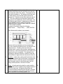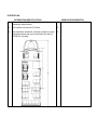
1
VEHICLE SPECIFICATIONS
F.O.B.
Flathead Eagle Transit
160 Kelly Road
Kalispell, MT 59901
SCOPE:
CURRENT MODEL BODY ON CHASSIS TYPE COACH CAPABLE OF SEATING TWENTY-FOUR
(24) FORWARD FACING AMBULATORY ADULT PASSENGERS, A DRIVER, A WHEELCHAIR
LIFT, AND TWO (2) WHEELCHAIR SECUREMENT STATIONS.
MINIMUM TECHNICAL REQUIREMENTS
DIMENSIONS:
1.
SPECIFICATIONS
Body Length - Please provide the body length.
1.
FURNISHED
2.
Body Width - Please provide the body width.
2.
3.
Wheelbase - 208” minimum and 228” maximum
wheelbase MUST be specified on cover page.
3.
MINIMUM TECHNICAL REQUIREMENTS
DRIVETRAIN:
1.
SPECIFICATIONS
Engine – 5.9 Cummins Diesel Engine ISB-02 with
215hp w/550 lb, -ft torque @ 1,600rpm. The engine
shall be located in the front of the vehicle. Electronic
fuel injection. Engine features:
A. Replaceable pleated paper element type air cleaner
FURNISHED
1.
A.
B. Oil Filter easily reached without removal of any
major component with a one-quart capacity and an
internal bypass valve.
B.
C. Factory oil filler extension neck
C.
D. The engine compartment shall be completely
sealed to prevent smoke and odors from entering the
D.
interior of the coach
E. The factory installed alternator, water pump, and
one 10 cubic inch displacement air-conditioning
compressors will be driven by a common serpentine
belt. The second 10 cubic inch air conditioning
compressor will be driven off the fan pulley.
E.
F. The engine will have an electronic protection
system. The electronic integral warning & de-rate
protection system shall be supplied. The system shall
activate in the event of low oil pressure or high coolant
temperature.
F.
G. The air cleaner shall be a single stage dry type with
a high-grade waterproof cellulose filter element. The
10 micron filter element and housing shall be
disposable. The air cleaner will be accessible from the
front of the vehicle. Intake air to the engine from the air
cleaner will pass through a 4-inch minimum diameter
tube.
G.
H. The chassis exhaust system will use a 3-inch
aluminized steel exhaust and a 4 inch aluminized tail
pipe and mounted on rubber isolators. The system will
meet all Federal and State regulations. The engine
and transmission that is being proposed should be able
to allow the bus to maintain a speed of forty-four (44)
miles per hour on a 2.5% grade.
H.
I. The diesel engine will be able to operate with
manufacturer specified Ultra Low Sulfur Fuels (ULSF)
diesel and/or at least a manufacturer specified 2% bio
diesel blend (B2).
I.
2.
Radiator/Coolant System - Heaviest-duty extra cooling
capacity radiator, water pump, and clutch-type fan.
Cooling system to be winterized for 40 degrees below
zero (0).
2.
3.
Transmission - The transmission shall be an Allison
model 2200 PTS five speed automatic transmission
minimum, cooled by an external “transmission oil
cooler” with capacity to match GVWR of vehicle and
filler extension neck for adding fluid. The oil pan on the
transmission will be quipped with a hex head magnetic
type drain plug. The transmission will be equipped with
3.
a heat exchanger located under the bottom tank of the
radiator. There will also be an external spin-on filter.
The transmission area will be lined with sound and heat
barrier materials to prevent any transmission noise to
the interior of the coach.
4.
Drive Shaft - The drive shaft(s) shall be completely
encircled by a metal guard that will prevent the shaft, if
broken or separated, from whipping through the floor of
the vehicle or from dropping on the ground, in
accordance to 49 CFR Part 393.89
4.
CHASSIS SPECIFICATIONS:
1.
SPECIFICATIONS
Chassis – 20,500 pounds GVWR minimum, MB55
Freightliner or equal. Please provide the make, model
and year. The GVWR must meet or exceed the vehicle
weight including all specifications and options.
FURNISHED
1.
2.
Frame - Factory frame or extension to frame (extension
must equal or exceed strength of factory frame and be
connected so no cracking may occur between the
connection on the factory frame and the extension)
must be sufficient length so no more than 12” of the
manufactured body extends over the rear end of the
frame. Frame extensions between the wheels are not
permitted. Overhang behind rear wheels may not
exceed 25% percent of the wheelbase.
2.
3.
Rear Axle and Differential - Truck-type, single rear axle
with dual rear wheels Gear Ratio of 4:10 minimum.
3.
4.
Springs and Shock Absorbers - The front and rear
springs shall have a ground load rating equal to or
exceeding the GVWR of the vehicle. Helpers spring(s)
shall be installed on the wheelchair lift side of the
vehicle to keep the bus level when fully occupied. This
vehicle will also be equipped with a MOR/ryd “RL”
suspension system or equal. If an equivalent part(s) is
installed, please provide a detailed part description
including a valid reason for such alteration.
Shock absorbers on each chassis shall be equipped
with front and rear, heavy-duty; double acting gas filled
shock absorbers, the highest rating available from the
4.
OEM. If an equivalent part(s) is installed, please
provide a detailed part description including a valid
reason for such alteration.
5.
Brakes - Dual hydraulic power assisted system with
disc-type brakes on the front and rear wheels. A hand
or foot operated parking brake shall be supplied with a
warning light on the dashboard. Vehicle must be
equipped with Anti-Braking System.
5.
6.
Wheels and Tires - Wheel and tire size and rating must
be of sufficient size and strength to meet GVW rating of
chassis. Tires to be steel-belted, all season 16” radial
with a 10 ply rating minimum. All tires must be the
same size. All wheels must be painted white to match
exterior bus body. Must have spare tire, wheel,
hydraulic jack, and lug wrench. Jack and lug wrench
must be secured in the vehicle at the time of delivery.
Spare tire and wheel sized the same as above and
stored on a mount on the back of bus with tire cover.
6.
7.
Steering - Each vehicle shall be equipped with OEM
power-assisted steering. Steering shall incorporate an
OEM factory installed tilt wheel feature and cruise
control.
7.
8.
Battery - Two (2) heavy-duty with reserve capacity of
160 minutes and with 700 Cold Cranking Amps (CCA)
and to be stowed in a slide compartment outside of
vehicle, no batteries will be underneath the hood. The
compartment for the batteries must have a sliding tray
for easy access when changing the batteries. The
compartment door must be lockable and be hinged.
The battery compartment must be enclosed on all sides
and be mounted and secured so no movement can
occur.
8.
9.
Alternator - 190 Amp minimum, 12 volt heavy duty
alternator by Powerline Model 24-216 or equal which
will include a Powerline wiring harness and voltage
regulator or equal.
9.
10. Electrical - All wiring shall conform to the current
applicable standards of the Society of Automotive
Engineers and be sufficient size to carry the required
current without excessive voltage drop.
The wiring shall be color-coded, function coded or
10.
permanently and continuously numbered for ease of
identification and must be continuously loomed.
A hard copy of the wiring diagram will be given to the
grantee on or before delivery that shows the chassis,
bus body, wheelchair lift, heaters, air conditioning and
all other accessories wiring system. All switches and
wiring circuits shall be protected with circuit breakers
and/or fuses and properly labeled for identification.
11. Gauges - Vehicle shall be equipped with the following
needle-type gauges:
A. Amp meter or Voltmeter
11.
A.
B. Headlight on indicator and headlight high beam
indicator; and directional signal and flasher action light
B.
C. Voltmeter and oil pressure gauge
C.
D. Fuel tank level gauge
D.
E. Speedometer with odometer
E.
F. Engine temperature gauge or over-heat warning
light
F.
12. Fuel Tank - A minimum of 75 U.S. gallons, full at time
of delivery. Access to fuel tank must be lockable.
12.
13. Horn - Dual
13.
14. Hood - To have latch release from inside of vehicle
14.
15. Wipers - Two heavy duty electric two-speed windshield
wipers with intermittent feature controlled by a switch
shall be furnished. Windshield washer is to be
included, with a reservoir easily accessible for filling.
15.
16. Undercoating - The entire underside of the body which
includes the floor members, the side panels below floor
level and the fender wells shall be undercoated, at the
time of manufacture, with a nonflammable resin type
polyoleum or equivalent. Any equivalent undercoating
must comply with MIL-C-62218A or MIL-C-0083933A.
If an equivalent part(s) is installed, please provide a
detailed part description including a valid reason for
such alteration. All opening in the floorboards and
firewall shall be sealed. Fenders and splash aprons
16.
(underskirt) of durable construction shall be provided to
provide maximum deflection of the wheel splash.
There shall be sufficient wheel well clearance for snow
chains.
17. Radio - AM/FM and compact disk player with a
minimum of four (4) speakers for passenger and driver
area. Must have digital tuner and clock. The unit will
be mounted in the dash and within arms reach of the
operator’s seat.
17.
18. Block Heater - A minimum 800 watts, with easily
accessible cord will be installed on diesel motors. The
cord will be extended from the engine block through the
front grill and secured.
18.
19. Back-up Alarm - Connected with back-up lights to
produce an intermittent sound to warn others when
vehicle’s transmission is shifted into reverse and
vehicle movement is backwards.
19.
20. Headlights - This vehicle will have day-time running
lights that will turn on when the vehicle is started and
will shut off when vehicle ignition is in the off position.
20.
21. Exhaust System - The exhaust system will exit on the
street side of the bus and behind the street side rear
duals. The exhaust will not interfere with the rear mudflaps.
21.
22. Bumpers - The front bumper will be OEM and the bus
manufacturer will provide the rear bumper. The rear
bumper must be a Transpec Energy Absorbing model
5000 bumper or a Romeo Rim energy absorbing
bumper or approved equal. Rear bumper is to include
an anti-ride feature. The highest possible quality of
construction is required. If an equivalent part(s) is
installed, please provide a detailed part description
including a valid reason for such alteration. If an
equivalent part(s) is installed, please provide a detailed
part description including a valid reason for such
alteration.
22.
BODY SPECIFICATIONS:
1.
SPECIFICATIONS
Body Structure - The coach shall have a heavy-duty
FURNISHED
1.
unit body-type structure. The sidewall structure to
consist of 3/4" x 3/4" 16 gauge steel and 3/4" x 1-1/2"
14 gauge steel tubing. The body structure shall be of
durable metal construction or laminated honeycomb
fiberglass adequately reinforced at all joints and points
of stress with sufficient strength to support the entire
weight of the fully-loaded vehicle on its top or side if
overturned. The vehicle shall safely withstand road
shock and other conditions found in transit operation.
The body shall be securely fastened to the underframe structure so that the entire frame shall act as
one unit without any movement in joining. Front, side,
and back panels shall be secured to the floor so as to
result in a permanent, fully integrated structural unit.
The minimum interior height is to be no less than 75”
inches measured from the floor at the center aisle to
the ceiling directly above. Ceiling height must be listed
on cover page of bid. Any compromise of the ceiling
height exceeding 3 inches at any point must be listed
in the exceptions. Roof shall consist of a steel cage.
The roof structure will consist of 3/4" x 3/4" 16 gauge
and 3/4" x 1-1/2" 14 gauge steel tubing. The exterior
surface shall be a gel coated surface and shall form a
one-piece seamless roof. Insulation in roof to be ¾
inch wood core or equivalent. No part of the roof
structure is to have gaps where no insulation is
present. Insulation MUST cover all areas of the roof. It
is the intent of the buyer to purchase a standard
industry modified vehicle insofar as it meets or
exceeds the following specifications. All modifications
shall comply with all applicable Federal Motor Vehicle
Safety Standards including FMVSS 220 rollover
standards. The manufacturer must be certified by the
National Traffic Safety Administration to manufacture
or alter vehicles in accordance with the Code of
Federal Regulations, Title 49, and parts 567-568. On
"cutaway" conversions, added bodies must be securely
fastened to the basic vehicle structure, bolted securely
through the chassis rail flange at the floor, and with
added reinforcing plates or comparable method. The
method of attachment must conform to chassis OEM
body builder's requirements.
Overall body length not to exceed 363” including
bumpers. Overall body width not to exceed federal and
state standards.
2.
Passenger Door and Step-well - Provide an
2.
electrically-actuated heavy-duty door opener. The
switch will be located conveniently in the control panel
within ½ arm’s length and about chest high for the
driver to operate. Switches located over the driver’s
head will not be accepted. The door must not intrude
into entry area and shall be securely affixed to
structural members of body to ensure rigidity. Door to
be double folding or split-type with a flexible soft rubber
cushion at least 1” in width on the meeting edge and
bottom of doors for seal to step-well with enough
pressure to remain tightly closed at highway speeds.
Driver must be able to secure the vehicle and gain
access from the outside.
No part of the step-well shall be outside of door when
closed (if any part of the step is outside the door when
closed the vehicle will not be accepted). Door to be
located on right side of the vehicle. Clear opening
entrance with a minimum of 36-inch door opening
width. The passenger door opening height is to be 78
inches minimum from top of first step to door header.
Ground to first step shall not exceed 11 inches plus or
minus 1 inch in height. Each additional step will have a
maximum 9 inch rise with 9 inch minimum depth. All
steps should be covered with anti-skid, ribbed, molded,
rubber tread. The vehicle shall have a heated stepwell entry to help keep the steps from having ice build
up during the winter months. The heated step-well will
be an electrical mat and have a switch on the driver’s
control panel to turn power on and off. Left side drivers
door to be supplied by chassis manufacturer.
3.
Interior - All interior panels will be vinyl-coated metal,
carpeted or equal alternative. All materials and
treatments shall be flame retardant and treated to be
easily cleaned. Colors of covering shall harmonize
with exterior colors. All surfaces and items of
hardware in passenger compartment having sharp
edges, corners, or angles shall be padded with a
heavy-duty vinyl-covered energy absorbing material for
safety. Interior wall panels may be made of Fiberglass
Reinforce Plastic (FRP), and the ceiling may be
covered with an automotive style cloth, and the driver’s
cab ceiling may be covered in padded vinyl (for better
sound absorption). All materials must be flame
resistant and meet FMVSS 302.
3.
4.
Floor – The floor on the bus will be a flat-floor, which
4.
means no wheel wells will be accepted. The floor shall
be covered with a minimum of ¾” inch exterior marine
grade plywood. The flooring must be a one-piece
seamless design with a .024 aluminum vapor barrier
laminated to the bottom of the floor. Vapor barrier
seams must be "S" locked together so that water
cannot get under barrier and cause the wood to rot.
The step-well, entrance area, center aisle, passenger
area, and also the wheelchair securement stations
shall be overlaid with 2.2mm Altro Transfloor
TFCR2233 Zeal Safety Vinyl Flooring or equivalent
(NOT CARPET). Seams and joints shall be
permanently sealed by heat welding. Color of floor
shall be Zeal and shall contrast with the seats so to be
easily distinguished by the visually impaired person.
All step edges shall have a band of bright contrasting
color (white or yellow) running the full width of the
leading edge.
5.
Aisle - 17” minimum width between seat cushions.
5.
6.
Windows - Driver’s door glass and front windshield
shall have manufacturer’s standard tint. The window in
front of the passenger door should be all glass and of
maximum size to view oncoming traffic. All windows,
except the windshield, rear, and doors shall be egress
transit type or a T-slide panel type, a minimum of 780
square inches. All side windows shall be top vented to
allow for ventilation and provide a clear view to the
outside from each seat position. All rear and
passenger glass is to be of the safety-type tinted to a
maximum of 31% light transmission in the passenger
compartment. Rear window shall have wide-angle view
lens to improve vision directly in back of the vehicle.
All passenger windows shall be 36” X 36”.
6.
7.
Emergency Exits - A 30-inch by 50-inch minimum,
egress type rear emergency exit will be provided to
meet FMVSS-217 standards. All passenger side
windows will be emergency egress type with the
fastening device to be located inside the vehicle. All
emergency exits will be marked with instructions for
proper use. No seats or other objects shall be placed in
the vehicle, which restricts passageway to an
emergency exit to less than 16 inches.
7.
8.
Doors - All doors but the passenger door must be
8.
lockable by key from outside of vehicle. If wheelchair
lift door and rear emergency doors are provided, they
must be keyed the same. All doors must be easily
operable from inside the vehicle.
9.
Ceiling Vents/ Escape Hatch - There will be two (2)
dual purpose roof vents that offer adjustable fresh air
ventilation and a release handle permitting operation
as an emergency exit (Transpec Triple Value Model
1100 or approved equal).
9.
10. Mirrors - Exterior mirrors to be Lucerix brand or equal.
Street-side & curbside mirror head to be a 15" mirror
head with street-side mirror bracket to be a break-away style cast window mount. Curbside mirror bracket
to be a break-a-way style with a cast fender mount.
The mirrors will be electric and heated and the control
shall be on the left side of the vehicle. The control can
be mounted in the driver’s control panel or in the dash
and must not diminish the appearance of the interior of
the vehicle. Clear and full view of right exterior mirror
through the wiper path must be provided. An interior
mirror 6” x 16” minimum shall be provided to afford a
view of all passengers. Mirror shall have metal
backing and frame with rounded rubber corners and
protected edges.
10.
11. Driver’s Seat - High-back driver’s seat with armrests
(stowaway), must have manually controlled air lumbar
support and covered with deluxe heavy-duty transit
grade cloth level (6). Driver’s seat shall have vertical
fore and aft slide. Certified shoulder and lap seat belt
with automatic retractor shall be provided. The driver’s
seat will be a Recaro Ergo MC II or equal. Seat must
be supplied with a 120 psi operating pressure
connected to a small reservoir tank. The fore-aft travel
must be a maximum of 10”. The seat must meet the
FMVSS 302, 207, and 210 requirements. The seat will
have left and right side arm rests. The seat will have a
three point safety belt, the shoulder part will be
mounted to the wall and the lap belt portion shall be
mounted to the seat frame. Color of driver’s seat and
armrest shall match with passenger seating. The
driver’s seat will be cloth even if the passenger seats
are vinyl.
11.
12. Interior Lights - A minimum of six (6) overhead dome
12.
lights mounted in the ceiling will be required to allow for
illumination for passengers entering and exiting the
vehicle. Mounted so that if equipped with overhead
storage racks they will not be obscured by contents of
racks. The overhead dome lights will not be mounted
on the storage compartments. Overhead entrance light
and two (2) entry step-well lights (one on each side of
the step-well) shall be provided to ensure illumination
of step-well. These lights shall illuminate automatically
when door is opened. Personal reading lights will be
provided for each seat position. The person in the seat
will have a switch to turn the light on/off. The driver of
the bus will have total control of turning the power to
the personal reading lights and dome lights. The
switch for the driver will be in the master control panel
(which will not be located above the driver’s head).
13. Exterior Lights - Exterior light shall be in accordance
with Federal Motor Carrier Safety Requirements. All
exterior lights should be “LED TRUCK LITE
LIGHTING” or approved equal. All exterior lights shall
be armored or recessed to prevent breakage from
minor impact. There will be one (1) light mounted
above or to the left of the entrance door and will
illuminate the ground around the door per ADA
requirements when the passenger door is opened.
Two (2) lights will be installed for wheelchair lift usage
at night. One (1) light will be mounted above the
wheelchair door and will illuminate the lift platform
when the platform is on the ground. This light must be
mounted outside of the vehicle; no light will be
accepted if mounted inside of the vehicle. The second
light will be a 3” minimum and will be installed below
the wheelchair lift door and will be mounted flush with
the body of the bus to prevent breakage and will
illuminate the platform when on the ground also.
Lights must be mounted securely to the vehicle and
wiring must be covered with light cover. The two (2)
lights above/below the wheelchair lift door and also the
passenger entrance door will not be LED lights. The
vehicle will also have mid-ship blinkers mounted above
the rear dual wheels. The clearance lights for front and
rear of the vehicle will also be LED lights.
If installing wheelchair lift lighting at locations other
than as specified, the lights must be mounted and
designed to illuminate the lift platform when it is on the
ground.
13.
14. Passenger Seats - Passenger seats shall be forward
facing. Double seats shall be 35” minimum width and
single seats 17” minimum width. The knee to hip
room between the seats is to be 29” minimum.
Minimum depth of seat bottom, measured on a
horizontal plane from the front of the seat to the point
where it joins the seatback, shall be 16”. (FREEDMAN
FEATHER WEIGHT MID-HI SEAT “ROCK SOLID” or
equal) Passenger seat back shall be mid-height, fully
padded of energy absorbent material and contoured to
provide full lumbar support. Seat bottom shall be fully
padded with neoprene foam. Seats to be covered with
heavy-duty deluxe transit grade repel for durability
level (6) and successful vendor must show proof of this
upon delivery of vehicle to the agency. Repel level (6)
material made by Freedman seating or equal to
(GRANTEE WILL CHOOSE SEAT COLOR AFTER
GRANT AWARD). All materials in seats to be flame
retardant. Folding armrests on aisle seats, and with all
seats having padded grab rails. Seat belts shall be
provided for all passenger seats with a minimum 40”
usable length above the seat (or the longest usable
length is preferred) and seat belts shall be of the
U.S.R. under seat retractor type. All seat mounts to
meet applicable Federal Standards and to be placed
so no more than 25% of the seat bottom overhangs
either end of mount. Pedestals shall be inboard to
eliminate tripping hazards. Seats shall be placed so
that wheel well protrusion into passenger legroom
space will be minimized. Successful vendor please
submit picture of seats with bid. All passenger seats
must have either padded grab rails or a durable, nylon
plastic handle. A minimum of two (2) integrated child
safety seats shall be installed in the farthest rear seats
possible. Space for two (2) wheelchairs directly behind
the driver will be 47 inches each, one directly behind
the other.
14.
15. Sun Visor- Padded adjustable sun visors with center
clip shall be provided for the driver side of windshield.
15.
16. Master Control Panel - Master control for interior lights
and exterior amber flashing lights on top corner of the
bus and heat/air conditioning located in driver’s station
area for easy access and control by the driver (NOT
TO BE LOCATED ABOVE DRIVERS HEAD). All
16.
switches will be labeled indicating what the switch does
not just be a symbol but also in writing.
17. Grab Rails and Stanchions - Padded vinyl-clad, heavyduty modesty panels shall be provided to the left of the
entrance door and directly behind the driver’s seat with
floor to ceiling stanchions provided at the aisle. There
will also be a modesty panel that will be mounted
directly behind the wheelchair lift. Modesty panel to be
3/4" thick and covered with white Formica. The edge of
panel shall be covered with a color coordinated plastic
edge around the entire perimeter. A floor to ceiling
stanchion and crossbar must be installed behind the
driver's seat. The cross bar must extend to the
sidewall area. Vinyl pads will only be accepted around
and above the entry doorframe, above the driver's door
(shelf area), above the w/c door, and around the rear
evaporator area. The stanchion shall not impair the
driver’s seat adjustment and should allow the driver to
move into the passenger area. The padded modesty
panel shall be 30” plus or minus 2” above the floor.
Handrail to be located in such a manner as to assist
passengers in getting on and off the bus. Grab rail on
each seat. There will one (1) ceiling mounted full
longitudinal grab rail installed that parallels the floor
aisle from end to end on the street side of the bus.
Modesty panel to be 3/4" thick and covered with white
Formica. The edge of panel shall be covered with a
color coordinated plastic edge around the entire
perimeter.
17.
18. Heating - High output front heater plus two (2) auxiliary
heaters located in the passenger section of the bus
must be seat mounted and be blow down heater or
wall mounted where designated only. The heaters
must not be mounted to the floor but will be mounted to
the seat frame. This will help with the cleaning of the
bus. The heater in the rear of the bus will be a wall
mounted heater and must be adjusted to the center of
the bus so the jack on the wheelchair lift can be used
when manually operating wheelchair lift. The heater
will also be mounted 12 inches from the floor.
Minimum 65,000 BTU’s for each heater. (NOTE) If
heater lines are installed on the exterior of body they
must insulated. The heater in the rear of the bus must
be a wall mounted heater or a heater that is mounted
under one of the seats in the rear row of seats.
18.
19. Air Conditioning - Air conditioning (R134A Freon)
specs on Carrier Transport Air Conditioning rear
mounted unit. Will not accept R-22 or R-12 or blended
Freon. The air conditioning system will be a minimum
of 65,000 BTU’s. Front dash AC unit shall be OEM
supplied. System shall operate in conjunction with the
heater/defroster system and share the same vent
system and shall be a four-speed fan type and operate
on R134A only. The rear mounted Carrier A/C
Industries Air Conditioning unit will be mounted inside
the van in the rear of the passenger compartment
secured to the inside of the roof. The A/C system shall
utilize a TM 16 Compressor on 134A Freon. The
system shall utilize a carrier AC Industries skirt
mounted condenser located on the roadside of the van
body and installed to minimize collection of road dirt
and facilitate maintenance. The condenser shall be a
Model CM-3 with three motors enclosed within the
condenser housing. The filter drier will utilize flare Oring type fitting connections for added leak protection.
A sight glass shall be located on the drier to assist with
system refrigerant charging. Condenser fitting
connections shall be O-ring type. Carrier unit to be a
AC-713MAX. The system will utilize Carrier AC
industries Model EM-1 evaporator in the passenger
area. Three-speed continuous duty permanently
lubricated long life motors with resistors are utilized to
limit amperage requirements.
The air conditioning system shall be controlled from the
driver’s area with arm lengths of a sitting driver. The
controls shall on/off and three speed blower switch and
thermostat switch. Components of the air conditioning
system shall be readily accessible for maintenance. All
hoses shall be refrigerant type. Hoses and fitting are
qualified to SAE specification J-2064 Type- D or E.
The successful vendor must certify as part of the bid
package in writing that the wiring for the air
conditioning circuits is adequate to withstand the
transient loads expected. These circuits are protected
with circuit breakers or thermal relays. When the
vehicle is shut-off the heating and air-conditioning
system shall be automatically shut off.
19
20. Paint - The bus body and chassis will be a gloss white.
Then there will be two additional colors. The first color
will be the major color. The second color will be the
20.
minor. The major and minor strips will run above the
windows both being one inch and will run on both the
street and curb side of the vehicle. The stripes for the
bus must be painted on. The lettering on the bus can
be either paint or vinyl and the agency can have a
maximum of 70 letters and can be a maximum size of
8”. This color scheme must include the gloss white
base plus two (2) additional colors for the stripes. See
the following paint scheme. Negotiations on lettering
will be handled between vendor and grantee.
(GRANTEE WILL CHOOSE PAINT AND LETTERING
AFTER GRANT AWARD)
For paint color please contact the following:
Eagle Transit
Cheryl Talley
(406) 758-5728
The following paint scheme is an example:
Schemes will vary depending on the manufacturer.
Any color scheme provided must be very similar to the
example shown. If bidding other than the paint
scheme shown, vendor must provide a sample/picture
with their bid. Color schemes that are not similar to the
example will not be acceptable. The standard color
schemes for Startrans Supreme, Goshen Coach and
Starcraft Bus are approved color schemes for this bid.
21. Insulation - Inside walls, ceiling and firewall area to be
adequately insulated with fire resistant, nonhyposcopic,
resistant to fumes, material to prevent condensation
and thoroughly sealed so that drafts cannot be felt
during normal operation, minimum R6 factor.
21.
22. Wiring - All cable and wiring shall be coded, and the
builder shall furnish complete wiring diagram marked to
show the code used. All added accessories and
electrical equipment shall be wired through a constant
solenoid energized by the vehicle ignition switch and
have a separate circuit braking system. All
22.
accessories will shut off when the key is shut off.
23. Safety and Other Equipment A. 24-passenger unit first aid kit will be mounted right
behind the driver’s seat on the stanchion/modesty
panel.
23.
A.
B. 10# rechargeable type A-B-C rate fire extinguisher
with metal head.
B.
C. Belt Cutter Q’Straint Q5-7590 or equal mounted in
driver’s area.
C.
D. Disabled vehicle-warning device (triangular
reflector kit) secured in vehicle interior.
D.
E. Fireproof utility blanket and storage case.
E.
F. Body Fluid clean up kit mounted right behind the
driver’s seat on the stanchion/modesty panel.
F.
G. Driver’s overhead storage compartment must be
lockable. This compartment is different from the one
over the windshield. The minimum size this
compartment can be is 15” wide by 15” high by 20”
long.
G.
H. Five (5) two-passenger Freedman Seating Fold-AWay Series with padded grab rails on each set or
equal.
H.
I. Two (2) 6” inch amber flashing warning lights
mounted on upper right and left rear of bus to be used
for Railroad Crossing, (lights will be “LED TRUCK LITE
LIGHTING” or approved equal). Control switch
mounted in Driver’s control panel (NOT MOUNTED
OVERHEAD).
I.
J. One (1) Driver’s Running Board mounted outside of
vehicle.
J.
K. Seatbelt extensions six (6) at the length of 12”
each. These seatbelt extensions will be able to be
used on any seat in the bus.
K.
L. A sign mounted above driver’s area stating in 2”
lettering the height of the outside of the vehicle.
L.
Sign to be provided on rear of bus stating in 4” lettering
minimum “BUS STOPS AT ALL RAILROAD
CROSSINGS”, this lettering will be black.
M. Vehicle should have all decals to meet ADA
Requirements.
PRIORITY SEATING SIGNAGE & WHEELCHAIR
LOCATION SIGNAGE
The vehicle shall have three decals showing that the
vehicle is wheelchair accessible. One of the decals will
be located on the right corner of the hood that is 4”x4”,
the next on the drivers front fender right below the
windshield that is 4”x4”, and the last one will be a
12”x12” and placed on one of the wheelchair doors.
M.
N. The rear of the bus body shall be marked with
strips of reflective NSBY material to outline the
perimeter of the back of the bus using material which
conforms to the requirements of FMVSS 571.131 and
the perimeter marking of rear emergency exits FMVSS
217. The perimeter marking of the back of the bus
strips of at least 1 3/4” reflective NSBY material shall
be applied horizontally above the rear window and
above the rear bumper extending marking outward to
the left and right rear corners of the bus. Vertical strips
shall be applied at the corners connecting these
horizontal strips.
The reflective material will be WHITE in color. The
red/white reflective material will not be accepted.
N.
O. Overhead storage compartment above the
windshield. This compartment will have a door that is
lockable but the compartment must be able to store
items in (blanket, coat, first aid kit and body fluid kit).
This is a different storage area then the driver’s
storage compartment.
O.
P. Mud flaps for front and rear tires.
P.
Q. License plate light must be recessed in the rear cap
on the driver's side of the vehicle, a recessed space
shall also be provided for the license plate. Light and
plate must be recessed so that it cannot be ripped off
or bent by a bus washer. License plate mounting may
be done by securely mounting the bracket to the rear
wall.
Q.
R. The vehicle will have an anti-ride system for the
rear of the vehicle.
R.
S. There will be three (3) sets of keys for the vehicle
and accessories. Each set of keys will be put on
separate key chains.
S.
T. Eight (8) Webbing loops Q’Straint Q5-7580 or
approved equal.
T.
U. Booster pump will be installed to help circulate
water through the heating system. The booster pump
will be installed inside the vehicle with a cover over it to
protect if from being damaged by the passengers.
There will also be a switch mounted in the driver’s
master control panel to turn the booster pump on and
off. The heater booster pump may be mounted to the
chassis frame rail only if the water lines leading to and
from the pump are insulated.
The booster pump switch is not required if the booster
pump operates automatically.
NOTE: ALL SAFETY EQUIPMENT IS TO BE
SECURED TO VEHICLE AND EASILY ACCESSIBLE
TO DRIVER.
U.
WHEELCHAIR LIFT AND EQUIPMENT:
1.
2.
SPECIFICATIONS
1.
Double door opening for a fully automatic electrohydraulic or electro-mechanical lift located on right side
of the vehicle right behind the passenger entrance door
(See Floor Plan). Minimum door height to be
measured from door jam to floor directly below.
Minimum door heights will be in compliance with
Federal ADA Regulations. One (1) door to be
equipped with an exterior handle and locking device the
other door will have a interior handle to prevent door
opening before drive is aware. The vehicle will also
have a door ajar alarm that will make a noise when the
wheelchair lift door is open. Each door will have top
mounted steel check-style device with minimum 25
pounds springs to be provided for door so it can be
secured in the open position. Windows in lift door shall
be smoked as are all other transit window in bus.
The wheelchair lift shall be electro-mechanical or
electro-hydraulically powered with a minimum tested
2.
FURNISHED
load capacity of 800 pounds and shall be totally selfcontained. Braun Model L917 and/or Ricon “S” Series
or equal. The pump on the wheelchair lift will be
located on the side of the passenger entrance door to
allow the passenger seat behind the wheelchair lift to
have legroom.
3.
The wheelchair lift must be of heavy-duty frame design
concealing all elements of power drive. All sliding
surfaces and load bearing surfaces must be
constructed with sealed roller or sleeve bearing with
adequate protection to prevent exposed greasy
surfaces.
3.
4.
The wheelchair-lifting device, electro-mechanical or
electro-hydraulic powered unit must operate in both up
and down modes. Any failure of the drive mechanism
shall cause the lift to fail in the fail-safe mode. The
power unit shall be 12 Volt electric motor operated and
a minimum of 1 HP of electrical power, 2 HP for
intermittent operation. The drive motor and the worm
gear driven connection must contribute toward a
condition that will prevent any slippage, creepage, or
would prevent the platform from overhauling. In the
event of a power failure, the lift platform shall be able to
manually or electrically be lowered with passenger or
raised without passenger. The electric motor shall be
solenoid operated and controlled by either a hand-held
switch on a pigtail or station operated at any location of
the vehicle. All switches outside the vehicle shall be
weatherproof protection covered. Switches on the
outside of the vehicle shall be protected, covered, and
labeled as to function.
4.
5.
The drive mechanism must have a positive up stop that
can be overridden without causing damage to vehicle
or lift, and must have a fail-safe release which is
capable of releasing the drive mechanism upon striking
the ground or an object. Chain driven, cable driven or
equipment solely dependent upon limit switches for
stopping in the up or down position is acceptable. This
will prevent the damage to the lift of the vehicle.
The lift platform shall have a non-slip reinforced floor,
capable of carrying small or balloon tire wheelchairs.
The lift corporation must have a location that is painted
on the platform were standees must stand when using
the lift to access the bus. The platform shall have a
5.
minimum size of 32” wide by 48” long, including the
front ramp safety guard. The platform shall have a
double activated safety guard system to facilitate
loading and unloading and prevent roll-off while lift is in
use. Platform should fold up easily and lock for storage
inside the vehicle when not in use. In the stored
position, platform must have easy visibility when in
direct line of sight through window. When in its stored
position, it should not rattle when driven over normal
paved highways. Platform shall be equipped with
handrails on both sides in compliance with Federal
ADA Regulations.
6.
Platform must have the capability to be manually
released without wrenches in case of failure of the
automatic store assembly. The lift shall be capable of
operating in a temperature range of -30 and +110 F.
The lift shall be installed so as to allow easy removal of
the lift and shall be readily accessible for repair and
maintenance.
7.
Lift controls shall provide appropriate mechanisms to
7.
ensure that the vehicle cannot be moved when the lift is
not stowed and so the lift cannot be deployed unless
the interlock is engaged. The vehicle will have the
Intelligent Lift Interlock system; this system will be
installed to inform the driver that the interlock system is
working correctly.
8.
Installation of the wheelchair lift shall not require
vehicle alterations that diminish or change the
structural integrity of the vehicle.
8.
9.
A complete operator’s and service manual and a
replacement parts list shall be provided with each lift
unit. The manual shall have detailed section covering
warranty, installation procedures, operating
procedures; service and maintenance procedures and
a trouble-shooting guide.
9.
10. Restraints for two (2) wheelchairs (See Floor Plan).
Restraints to be adjustable to accommodate all
wheelchair types. Wheelchair restraint track must be
Sure-Lok “L” Fitting Series or equal and must be
mounted flush with floor running front to rear from
directly behind the driver seat to the first stationary seat
on the street side of the bus. Along with shoulder
6.
10.
harness and lap belt to meet ADA. Two (2) sets of
Retractable wheelchair restraints must be Sure-Lok
Retractor Model FF627S-4C, two (2) Lap Belts
FE200842, two (2) Shoulder Belts FE200732, and two
(2) storage containers FE200746 or equal (See Floor
Plan). The restraint shall be of sufficient strength to
retain an occupied wheelchair load of 5,000 pounds
under crash conditions. Certified seat belts and
shoulder harness shall be provided for the wheelchair
occupants. The successful vendor will supply a
storage container with a lid to store unused wheelchair
restraints.
INFORMATION TO BE FURNISHED WITH EACH VEHICLE AT TIME OF DELIVERY
1.
2.
INFORMATION
All items listed below must be in one three ring binder
for the agency. Owner’s manual is not adequate.
A. Drawing showing wiring schematics of all parts of
the bus (chassis, bus body, wheelchair lift, heaters, air
conditioning, all accessories and auxiliary circuits).
FURNISHED/DATE OF DELIVERY
1.
A.
B. Repair and parts manual for wheelchair lifts
B.
C. Repair and parts manual for bus body
C.
D. Air conditioning system
D.
E. Heating system
E.
F. Seating (Driver’s and Passenger Seats)
F.
G. Hose, valve and wiring diagrams
G.
Anticipated date of delivery (cannot exceed 100
working days APO:)
2.
MISCELLANEOUS INFORMATION AND TECHNICAL SPECIFICATIONS FOR ALL VEHICLES
1.
INFORMATION/SPECIFICATIONS
Warranty Information – Description of warranty
including time and mileage limits for body and chassis,
a list of authorized dealerships in the local area that will
have responsibility for warranty work, and an outline of
the procedure involved in the fulfillment of warranty
work.
APPROVED/INFORMATION
1.
2.
Inspections - Vehicles shall be thoroughly inspected
during construction and /or upon completion to ensure
that all equipment is installed and operating properly.
A. Unit requested to be new and standard equipment
unless otherwise specified. To be dealer prepared and
ready to be placed into service when delivered. To
include permanent Montana temporary license plate.
2.
A.
B. There shall be no sharp corners that will cause
injury to passengers on the unit. All corners that could
cause injury to passengers shall be slightly rounded
and filed smooth.
B.
C. All material installed shall be new and free of rust.
C.
D. No wires shall be visible on the exterior or interior of
the unit.
D.
E. All units shall be thoroughly cleaned and weather
sealed before inspection and delivery. Tests shall be
performed to ensure that the unit is dust proof,
watertight, and fume proof.
E.
F. All signs may be painted or vinyl decals and
properly placed.
F.
G. All holes, not used by manufacturer to install OEM
equipment, will be covered with a cover or plug
matching adjacent colors.
G.
3.
Exceptions to Minimum Specifications – List of any
exceptions to the specification you wish the Purchaser
to consider. Any and all exceptions to the
specifications MUST be listed. If no exceptions are
listed, the equipment bid will be considered to meet or
exceed the specifications.
3.
4.
Equivalent Equipment – List of any equivalent
equipment to the specification you wish the Purchaser
to consider. Any and all equivalent equipment to the
specifications MUST be listed. If no equivalent
equipment is listed, the equipment bid will be
considered to meet or exceed the specifications.
4.
5.
Other Information – If more space is needed, attach
additional sheets.
5.
FLOOR PLAN
1.
INFORMATION/SPECIFICATIONS
The wheelchair lift will be located right behind the
passenger entrance door.
1.
APPROVED/INFORMATION
2.
This vehicle will not have ICS seats.
2.
3.
Also should be included is a storage container to store
unused tie-downs that can be secured to the wall (1)
FE200746 vinyl bag.
3.