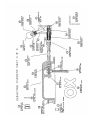
1
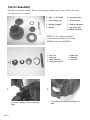
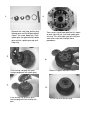
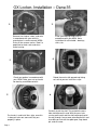
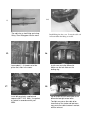
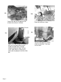
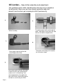
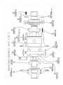
Serial Number
_____________________
DANA 35 (27/30 spline) OX Locker
This is your OX Locker installation manual for the DANA 35. This
installation guide is illustrated with a Jeep TJ (rear).
Note: Use of an installation kit that includes the following Timkin
bearing and race part numbers:
•
Bearing- 27 spline LM501349/ 30 spline LM102949
•
Race- 27spline LM501314/ 30 spline LM102911
You must use this manual in conjunction with your vehicle’s service
manual. Professional installation by a certified mechanic is
recommended.
Note: Depending on the year, make, and model of your vehicle,
some deviations and modifications may be needed during
installation:
1.
Routing of the cable
2.
Placement of the shifter.
The OX Locker is proudly made in the USA – Pat. No. 6,432,020
If you have any installation questions please contact us at:
OX/FMG
11625 Prosperous Drive
Odessa, FL 33556
Tech Support: 877-694-7699
[email protected]
www.OX-USA.com
Carrier Assembly
OX Locker needs final assembly. Remove all packaging including any tie wraps. Picture shows the
parts that need to be assembled:
8 – bolts, ¼-28 thread
8 - spring washers
1 - small carrier cap
1 - thrust washer
1 - locking ring gear
1 - locking side gear
4 - springs
1 - big carrier cap
(attached to carrier)
NOTE: Use of a complete install kit is
recommended (not included) or bearing
#LM501349 and race #LM501314
1 - long shaft
1 - snap ring
1 - spider gear cap
1 – spider gear washer
1.
2.
Install the 4 springs in the 4 chamfered
holes.
Page 1
1- spider gear
1 – dowel pin
1 – set screw
Install thrust washer behind locking side
gear.
3.
4.
Remove the small cap, locking ring,
locking gear and the following parts
shown- set screw, dowel pin, shaft,
spider gear (on opened end) spider
gear washer, spider gear cap and
snap ring
Your carrier should now look like this- open
on one side with the shaft and spider gear
missing. This will enable you to install your
axles and c-clip later through these
procedures
5.
6.
Install locking side gear with gears
facing engagement with spider gears
Slide the ring gear around the carrier.
7.
8.
Install locking ring gear with gears
facing engagement with locking side
gear
The flat side must be facing up!
9.
10.
Install small carrier cap – align holes,
make sure it slides into locking side
gear smoothly. NOTE: Make sure this
cap sits flush with all 8 cams – if cap
is not flush, it could cause severe
damage to the carrier
Install the ¼ bolts and spring washers.
Apply high strength loctite to bolts.
1
10
2
9
3
12.
11.
8
4
7
6
Torque ¼ bolts to 12 FT LBS. Note:
when tightening, tighten the bolts in the
following pattern: 1 – 5 – 7 – 3 – 8 – 4
–6–2
13.
Page 2
5
Install bolts from the original ring gear –
we recommend installing new bolts.
Torque them to manufacturers
recommendations using the following
pattern: 1 – 6 – 8 – 3 – 10 – 5 – 7 – 2 –
9 – 4 Note: ring gear is a tight fit on the
carrier.
OX Locker Installation – Dana 35
tm
1.
2.
Remove tires, brakes, rotors, and axles
in accordance with your vehicle’s
manufacturer’s service manual (MSM).
Drain oil then remove carrier. Now is a
good time to check seals and clean
entire housing.
Install your bearings and shims in
accordance with your MSM. Note:
installation kit not included – bearings,
shims, etc.
4.
3.
Rotate the carrier with opened end facing
out so that you can install the c-clips.
Check your pattern in accordance with
your MSM. Note: gear set up should
be done by a certified mechanic
5.
Push axles in and install the c-clips, once this
is done pull axles out some until they are
properly in place
Page 3
6.
Carefully Install the shaft. The end with the cross
hole should be on this end. With the cross hole
running north/south and the shaft not be pushed all
the way through. Leave some extending out this end
to enable you to install the spider gear, cap, dowel
pin, and set screw.
8.
7.
Install the spider gear cap (align the
key into the groove in the carrier) –
do not push the cap all the way
down so that you have room to
install the dowel pin.
Inset the spider gear and washer
9.
10.
Push the spider gear in until you see
the grove where the snap ring will be
placed.
Install the dowel pin an then the
set screw. Add High Strength
Lock-tite to the set screw prior to
installation.
11.
12.
Install the snap ring into the
groove. Make sure snap ring is
fully seated into groove.
Torque bearing caps to 80 FT LBS.
Install axles, rotors, brakes, and tires in
accordance with your MSM.
14.
13.
The cable has a short fitting and a long
fitting. Short fitting goes into the cover.
15.
Install fitting into the cover. Screw the cable rod
in first and then the fitting as needed.
16.
Leave about 2 – 3 threads out of the
piston that slides in the cover.
17.
Install cover on to the differential.
Make sure the fork slides on the
locking ring.
18.
Install diff cover bolts supplied and
torque to 30 FT LBS. Note: Use gasket
or sealant in accordance with your
MSM.
Do not make the turn coming out of the
differential too tight or too loose.
Too tight may cause the cable to be
inaccurate on the stroke and too loose
may cause the cable to come in contact
with the exhaust.
19.
20.
Secure the cable on the opposite side
of where the exhaust is located
Follow the routing as shown.
Center Console
22.
21.
Drill Hole
Open a 7/8” hole through the floorboard,
then cut it oval from front to rear to
enable the cable to pass through
without interference. Note: for best
results, open hole 16” to the rear of
where you are going to install the shifter
box.
Page 4
Give the cable plenty of slack to
allow for articulation. No sharp
turns or kinks.
OX Lockertm – New shifter assembly and adjustment.
The installation of the shifter should be done after the cover is placed on
the differential. Make sure you have already routed the cable and
placed it near to where you are going to install it permanently.
1.
2.
Thread the piston into the rod end of the
cable. Note: Make sure to leave 5/8” gap
and to use medium strength loc-tite
Shifter Assembly
3.
4.
Place spring on piston and into the
swivel fitting on the shifter.
5.
Shift several times into lock and unlock.
Check the shift on the unlock position
(make sure it is still touching, if not
adjust appropriately, then tighten the
two screws on the swivel fitting, tighten
the lock nut, and install your shifter.
Page 6
Thread the swivel fitting until it touches
the shift rod as shown.
OX Locker installation Notes:
When installing the cable, fasten to as
many areas as necessary to keep it
from rubbing against unwanted
surfaces. You may want to apply
some chaffing tape to areas of high
friction. Tape not included.
When draining oil, use bottom drain
plug. If you remove the cover you
have to readjust the shifter.
When installing the knob, don’t thread
all the way down. Make sure that the
shifter can shift clear.
Mount the shifter(s) in an easy to
reach and easy to maintain place and
in a straight as possible path with the
cable (do not kink the cable).
SAFETY FEATURE: To avoid
accidental shifting or tampering with
the shifter while driving on the street,
you can thread the knob all the way
down in the unlock position. Note:
Remember to back off the knob when
you are ready to use your locker off
road.
Page 7
OX Locker™ Limited Warranty
ONE YEAR limited warranty on manufacturer defects:
• This warranty covers only parts originally supplied by OX/FMG if they are shown to have a
manufacturer’s defect. All parts must be returned to OX/FMG and if upon inspection by OX/FMG, they
were installed correctly in their intended application and were not mistreated they will be repaired or
replaced.
• This warranty does not cover vehicles with modified high-horsepower engines (modified beyond the
original manufacturer’s recommendation).
• OX/FMG recommends professional installation by a qualified mechanic. Purchaser/user assumes all
risks and liabilities in connection therewith.
• Installation and use of these parts constitutes acceptance of all the above stipulations. If the
purchaser/user does not agree to these terms, the OX Locker should not be installed and returned to
the supplier.
•TO REDEEM your coverage you must return the defective part(s) along with your claim #. Claim #
can only be obtained by calling or e-mailing OX/FMG. OX/FMG will make a complete evaluation of
your claim before validating it. 1-877-694-7699 or [email protected].
OX Locker™ - US Pat. 6,432,020
Questions for OX/FMG :
Page 8
Service
1.
An initial oil change at 1500 miles is recommended. After this, periodic oil changes should be
done in accordance with the vehicles owner’s manual.
2.
If differential is immersed in deep water, the oil inside your housing could get water
contamination. An oil change is recommended.
Cable Installation Recommendation
1.
Use a fuel line hose on rubbing surfaces.
2.
Cut hose on one side, slip over cable, and use a tie wrap on each end to hold it in place.
3.
Don’t create too many bends or bind the cable. This will affect the stroke adjustment.
4.
Make sure that the cable exits the floor board or the firewall as straight as possible.
Shifter Installation Recommendation
1.
We recommend to mount the shifter on an open area with easy access.
2.
When adjusting the shifter, it should be kept close to the place it’s going to be mounted.
How To Engage And Disengage
1.
The OX Locker tm can engage and disengage by simply shifting from (O) open to (X) locked.
2.
The OX Locker tm is intended to be engaged only when the terrain ahead requires extra traction
control. NOTE: This product is not intended to be used on paved streets under any condition.
This product is intended for OFF ROAD USE ONLY.
3.
To engage the locker on rough or slippery terrain, move the shifter to the (X) position, the locker
will engage almost immediately. To disengage move the shifter to the (O) position, the locker will
disengage as soon as the load is release from the differential, this happens almost immediately.
4.
The OX Locker tm can be engaged at any speed.
Troubleshooting
Page 9
Problem
The locker seems to be properly adjusted, but after a few cycles it looses it’s
adjustment.
Solution
Check for excessive slack in the cable adjustment, also look for a very tight
bend or an area that is being pressed between two parts, and also check to
see if the cable was burned by the exhaust. The shifter should have tension
as soon as you start to shift into the lock position.
WARNING: Do not engage the OX Locker tm on paved roadways under any
conditions (dry,rain, snow etc.) or high traction surfaces, this makes the
steering very difficult and puts unnecessary strain on the drive train. This
could cause serious damages and/or it could even be fatal.
PARTS LIST FOR DANA 35 (27 & 30 spline).
ITEM
PART NUMBER
PART NAME
QTY.
1
2
3
4
5
6
7
8
9
10
11
12
13
14
15
16
17
18
19
20
21
22
23
24
25
26
27
28
29
30
31
32
33
34
35
36
37
38
39
OXD35-01
OXD30-02
OXD30-03
OXD30-04
OXD30-05
OXD30-06
OXD35-07
OXD30-08
OXUNP-09
OXD35-10
OXD30-11
OXUNP-12
OXUNP-13
OXD35-14
OXD30-15
OXD35-16
OXUNP-17
OXD35-18
OXUNP-19
OXUNP-20
OX46001
OXSHIFTER-01
OXSHIFTER-02
OXSHIFTER-03
OXSHIFTER-04
OXSHIFTER-05
OXSHIFTER-06
OXSHIFTER-07
OXSHIFTER-08
OXSHIFTER-09
OXSHIFTER-10
OXHSIFTER-11
OXSHIFTER-12
OXSTICKER
OXUNP-21
OXUNP-22
OXUNP-23
OXUNP-24
OXUNP-25
BIG CARRIER CAP
THRUST WASHER
SIDE GEAR
SPIDER GEAR
LONG CROSS SHAFT
SMALL THRUST WASHER
CARRIER CASE
LOCKING SIDE GEAR
SPRING S-770
LOCKING RING
SMALL CARRIER CAP
¼ SPRING WASHER
¼ -28 GRADE 8 BOLT
CENTER BLOCK
SMALL SHAFT
DIFFERENTIAL COVER
DIF. COVER PISTON
DIF. COVER FORK
½” RETAINING RING
O-RING 568-12
LOCKER CABLE ASSY.
SHIFTER BOX
SWIVEL FITTING
SHIFTER SPRING
SPRING PISTON
SPRING SLEEVE
3/16 X 1.5 DOWEL PIN
TRIGGER CUP
TRIGGER SPRING
SHIFTER FORK
SHIFTER KNOB
PHILLIPS PAN HEAD SCREWS
SHIFTER BRACKET
3M REFLECTIVE GOLD
OIL FILL PLUG
OIL FILL PLUG WASHER
DRAIN PLUG
HEX FLG BOLT 5/16-18 X ¾
7/32 X 1 ½ SPRING PIN
1
2
1
4
1
4
1
1
4
1
1
8
8
1
2
1
1
1
2
1
1
1
1
1
1
1
1
1
1
1
1
6
1
1
1
1
1
10
3