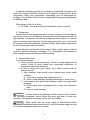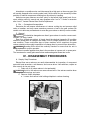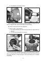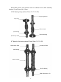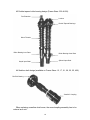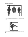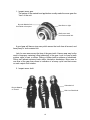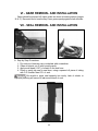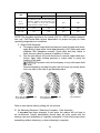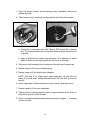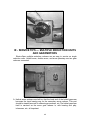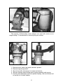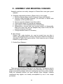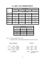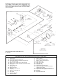
1
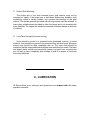
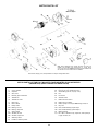
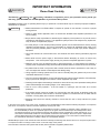
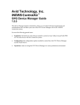
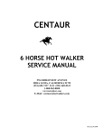
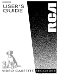
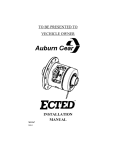
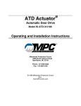
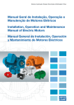
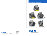
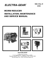
ELECTRA-GEAR
¨
SM-3 Rev. E
2002
WORM REDUCER
INSTALLATION, MAINTENANCE
AND SERVICE MANUAL
ELECTRA-GEAR
A REGAL-BELOIT Company
1110 N. Anaheim Blvd. ¥ Anaheim, California 92801
Telephone: (800) 877-4327 ¥ (714) 535-6061 ¥ Fax: (714) 535-2489
www.electragear.com ¥ Email: [email protected]
Today, with more than 100,000 square feet, over 100 employees and a world
class manufacturing operation, Electra-Gear is a leading producer of mechanical
and electrical motion control products serving a broad array of markets.
The Electra-Gear team prides itself on consistent, fast delivery of quality products
which meet the customersÕ specific needs. Our products are at the heart of what
drives your world and you will find them used in food processing, material
handling, chemical process and waste treatment, marine and health equipment.
Electra-Gear holds the distinction in our industry to offer several firsts:
¥
First to offer reducers, gearmotors and electric motors using aluminum
castings
¥
First to utilize rolled worm technology, a highly automated method of
producing a worm
¥
First to introduce the modifiable worm gear drive providing customers the
ultimate in mounting flexibility
What distinguishes Electra-Gear from its many competitors?
¥
Aluminum Construction (Reducers and Motors)
◆ No Rust
◆ Light Weight, High Strength
◆ Excellent Heat Dissipation
◆ Non-corrosive
¥
Surface Finish (Platinum Finish)
◆ No Paint
◆ Bright, shinyÑaesthetically attractive
◆ Optional polymer washdown finish (Platinum Plus)
¥
Short Lead Times
◆ Guaranteed Same Day/Next Day Service
◆ Aggressive VIP Service for Critical Situations
TABLE OF CONTENTS
I
INSTALLATION ................................................................................. PAGE 1
A. General Provisions
B. Solid Shaft Mounting
C. Hollow Shaft Mounting
D. Long Term Storage
II
LUBRICATION................................................................................... PAGE 2
A. Recommended Lubricants
B. Oil Fill Capacities
C. Continuous Duty
D. Intermittent Duty
E. Oil Filling Procedures
III
MAINTENANCE ................................................................................ PAGE 7
A. Run In Period
B. Oil Change Timetable
C. Maintenance Check Points - Trouble Shooting
1. Oil Leaks
2. Temperature
3. Vibration / Noise Level
4. Dirt / Contaminants
5. General
IV
DISASSEMBLY PROCEDURES ....................................................... PAGE 9
A. Step By Step Procedures
B. Internal Parts Evaluation
V
BEARING REMOVAL AND INSTALLATION .................................... PAGE 16
A. Ball Bearings and Bearing Cones
B. Bearing Cups
C. Bearing Part Numbers and Mfg. Part Numbers
VI
GEAR REMOVAL AND INSTALLATION .......................................... PAGE 20
VII
SEAL REMOVAL AND INSTALLATION ........................................... PAGE 20
A. Step By Step Procedures
B. Electra-Gear and Manufacturer Seal Part Numbers
VIII
ASSEMBLY PROCEDURES ............................................................. PAGE 22
A. Shimming Required (Change of Bearings or Gearset)
1. Worm Shaft Assembly
2. Gear Shaft Assembly
B. Shimming Complete - Final Assembly
IX
SERVICE TIPS - MULTIPLE REDUCTION UNITS
AND GEARMOTORS .................................................................. PAGE 25
X
ASSEMBLY AND MOUNTING CHANGES....................................... PAGE 28
A. Output Shaft
B. Adaptable Base
C. Double Worm
D. Convertibles
XI
BOLT / NUT TORQUE SPECIFICATIONS ........................................ PAGE 30
XII
PARTS LIST ...................................................................................... PAGE 31
I - INSTALLATION
WARNING
Improper installation of the gear reducer may cause injury to
personnel, gear reducer failure, or damage to driven equipment. Load conditions
must be within the published catalog ratings with the recommended A.G.M.A.
service factors properly applied.
SAFETY
WARNING
Rotating equipment is potentially dangerous and should be
properly guarded. The user is responsible for checking all applicable safety codes
in his area and providing suitable guards.
A. General
The reducer should be mounted on a flat surface on the machine or
foundation, securely bolted down and accurately aligned. Shims under the
mounting base should be used when required to provide a level mounting surface.
B. Solid Shaft Mounting
The output shaft can be connected to the load by flexible coupling, sprocket
and chain, sheave and V belt, or pinion. Check to insure proper alignment and
tension of all components. If sprocket, sheave, or pinion is used, mount as close
to gear housing as possible to minimize bearing load and shaft deflection.
Overhung load must be checked to make certain it does not exceed published
capacity.
When couplings, sheaves, sprockets, or pinions are mounted, it is important
that extreme care be used. It is quite easy to damage internal parts by heavy
blows used in trying to drive one of these parts on the shaft. It is recommended
that a bore be selected to give a light driving fit. If a press fit is required, it is
suggested that the external element be heated to assure an easy assembly.
Heating beyond 250 degrees F. (121 C.) is not recommended, as heat conducted
along the shaft, may damage the shaft seal.
1
C. Hollow Shaft Mounting
The torque arm of the shaft mounted worm gear reducer must not be
mounted too rigidly. If the torque arm is held down without any flexibility, shaft
eccentricity, which is usually present, can overload the bearings of the gear
reducer. The flexible grommet provided with all torque arms must be retained, or
some other suitable means provided to allow the torque arm to be mounted with
some flexibility. The torque arm should be mounted in tension (based on direction
of rotation).
D. Long Term Storage (6 months and up)
Units should be stored in a protected area (preferably indoors). If stored
outdoors, they should be covered to be protected from rain and snow. Wherever
stored, units should be filled completely with oil. The input shaft should be
rotated so that the output shaft makes at least one revolution per month. The input
and output shafts should be covered with grease to protect from corrosion and
rust. At start up time, completely drain storage oil and fill to proper oil level with
the correct lubricant.
II - LUBRICATION
All Electra-Gear worm reducers and gearmotors are shipped with oil unless
specified otherwise.
2
A. Recommended Lubricants
Ambient Temp.
Range (F.)
Manufacturer & Lubricant Name
Getty - Veedol Asreslube 98
Getty - Veedol Asreslube 95
Getty - Veedol Asreslube 90
Getty - Veedol Asreslube 86
Lubr. Eng. - Almasol 609
Lubr. Eng. - Almasol 608
Lubr. Eng. - Almasol 607
Mobil - Mobil Extra Hecla Super
Mobil - Mobil Cylinder 600W
Shell - Omala J-460
Shell - Valvata J-460
Texaco - Meropa 680
Texaco - Meropa 460
Texaco - Meropa 220
+100
+50
+40
+25
+45
+32
+15
+50
+32
+40
+40
+45
+32
+15
to
to
to
to
to
to
to
to
to
to
to
to
to
to
+150
+105
+100
+90
+125
+105
+70
+125
+100
+115
+105
+120
+100
+75
A.G.M.A.
Rating
8EP
7EP
6EP
5EP
8
7
5
8
7
7EP
7
8EP
7EP
5EP
—Special Wide Temperature Range Lubricants—
Kendall - Three Star
Mobil - Mobil SHC 634
Mobil - Mobil SHC 629
Mobil - Mobil SHC 626
-10
0
-25
-40
to +100
to +135
to +100
to +40
7
7EP
5EP
3EP
—Special Cold Duty Lubricants—
Conoco - Polar Start 600
Lubr. Eng. - Almasol 606
Mobil - Mobil SHC 624
Shell - Donax A.T.F. T-6
-40
-10
-55
-55
3
to
to
to
to
+10
+40
0
+5
3EP
Ambient temperature range is based on 1.0 service factor. Lubricants (listed
on page 3) are compounded for use in worm gear reducers. Some contain
non-corrosive, extreme pressure additives. Do not use lubricants that contain
materials that are toxic. Avoid use of such lubes that bring harmful effects. If in
doubt, consult your local lubricant supplier. Use only A.G.M.A. rated worm gear
lubes.
B. Oil Fill Capacities
Due to the numerous shaft, base, and mounting configurations of ElectraGear worm reducers, it is impossible to pin-point the exact amount of oil to be
used in each unit. Please use the following chart as a guide only for ordering oil.
U.S. Pints
Frame Size
Continuous Duty
Intermittent Duty
13
.50
.70
17
.90
1.50
21
1.10
2.00
26
1.80
3.40
30
2.80
5.00
35 (or 350)
3.50
7.00
400
4.00
9.25
500
8.00
17.00
600
11.00
26.50
C. Continuous Duty
Continuous duty is defined as running more than 30 minutes in an hour. If the
unit is going to be run on a continuous basis (more than half the time), it should
be filled to the continuous duty (low) level. See diagram next page.
4
D. Intermittent Duty
Intermittent Duty is defined as running less than 30 minutes in an hour, or with
an input speed of 800 RPM or less. All double reduction worm reducers should
have the secondary box filled to the intermittent (high) level.
Oil Level and Mounting Positions for Electra-Gear Worm Reducers
*These positions are not recommended, because the high speed oil seal must support the full head of gearcase oil.
E. Oil Filling Procedures
Electra-Gear Worm Gear reducers are easily filled to the proper level by
following these steps:
1. Remove pressure relief valve or breather.
2. Remove proper oil plug for oil level desired.
3. Insert lubricant through breather plug hole.
4. Pump oil into unit until oil runs out of hole where oil level plug was.
5
Electra-Gear reducers have many plugs on them designed to be an aid in oil
filling and removal and breather location. Your mounting position and duty cycle
will have an oil plug that corresponds to it. The breather should be located at the
highest position possible.
HORIZONTAL MOUNTING
Breather Location
Intermittent Oil Level
Continuous Oil Level
Oil Drain
Electra-Gear double reduction worm gear reducers have two oil
reservoirs. Fill both to proper level before operating. Use preceding page and
below as a guide.
CAUTION
6
III - MAINTENANCE
A. Run In Period
The maximum efficiency of Electra-Gear worm gear reducers is obtained after
a Òrun inÓ period. The length of time required will depend on the load applied and
will be 8 to 12 hours at rated load, and considerably longer at light loads.
During Òrun inÓ, higher than normal motor currents, lower efficiency, and lower
output torque can be expected.
CAUTION
Overloading will not decrease Òrun inÓ time, but may cause severe
wear.
B. Oil Change Timetable
1) Standard Mobil 600W Lube
Drain and refill oil after first 100 hours of operation. Under normal conditions, change oil every 2000 hours of operation or 6 months, whichever
comes first. Check ambient temperature limits of your oil to make sure it
matches ambient conditions.
2) Synthetic Lubricants such as Mobil SHC 600 Series
Under normal conditions, change oil every 4000 hours of operation or
every year, whichever comes first.
C. Maintenance Check Points - Trouble Shooting
1) Oil Leaks
There are several possible places for oil to leak out of worm gear reducers:
a) Oil Fill and Drain Plugs - when oil is changed, plug threads should be
coated with non-hardening pipe thread sealing compound. Check for
tightness on these fittings.
b) If oil is leaking at pressure relief valve or breather:
1. Check location - Is pressure relief valve or breather at highest
location?
2. Check oil level - overfilling (to intermittent level in a continuous operation) will cause oil to foam through.
3. Check oil type - the wrong type of oil will foam excessively. Refer to
lubrication section.
c) Input Bearing Caps and Output Sideplates - output sideplates and input
bearing caps should be tight against reducer housing (check bolts) and
should have a bead of silastic around inside machined fit where cap fits
to reducer housing. See Final Assembly Procedures for more details.
(Page 24)
7
If sideplate or bearing cap bolts are working loose repeatedly in operation, the
whole drive system should be checked over in detail for: overhung load, shock
components, faulty drive components, overloading, and be reevaluated accordingly. Consult Electra-Gear Service or Application Engineering Departments
for additional help.
Other places to look for oil leaks:
e. Oil Seals Ð See seal removal and installation section, page 20.
2. Temperature
Check actual oil bath temperature after running (or during). Oil bath temperature should not be over 200 degrees. Generally the oil bath temperature will rise
approximately 100 degrees over ambient temperature (based upon a 1.0 service
factor, continuous duty). Excessive oil bath temperature after Òrun inÓ period may
be a signal of lubricant breakdown, excessive loading, high ambient temperature,
or other internal gear reducer problems.
Inspect lubricant and internals of the reducer. Check to see if heat is localized
(around a particular bearing or bearings). If so, disassemble and evaluate all
parts, change bearings and observe while operating.
3. Vibration/Noise level
If noise level changes:
a. Check all drive system components. Check for proper alignment and
tension. Check for noise coming from components themselves, or
somewhere else in the machinery.
b. If noise is coming from gear reducer, try to identify location and frequency of noise.
1. High frequency (high speed) noises indicate input (worm shaft)
problems.
A. Check input coupling area (alignment and fit.)
B. Listen to input bearings (through stethoscope or screw driver.)
2. Low frequency (low speed noises indicate output (worm gear shaft)
problems.
A. Check output shaft coupling/sprocket or other load connection
area.
B. Listen to output bearings.
CAUTION
Constant noise at any bearing could be caused by lack of lubrication, lubrication breakdown, bronze filings from worm gear wear, or other contaminants. Disassemble and inspect unit as soon as possible.
WARNING
Make certain that the power supply is disconnected before
attempting to disassemble and inspect the unit. Lock out the power supply and tag
it to prevent unexpected application of power.
8
Intermittent or repetitive noise could be caused by a high spot on the worm gear (this
will usually disappear after running under load). Noise could also be caused by broken
particles of internal components resulting from shockload or handling.
Helical worm gear reducers are often ÒnoisyÓ in the helical (high speed) end. A constant, whirring sound is normal and may disappear after Òrun inÓ. If noise is excessive
after Òrun inÓ, contact Electra-Gear Service Department.
4. Dirt Ñ Contaminant Accumulation
Excessive dirt will hamper effectiveness of reducer cooling fan and pressure relief
valve or breather, and may cause excessive pressure or heat in the gear reducer. Be
careful not to allow any contaminants to enter the gear reducer or build up on the outside.
5. General
CAUTION Oil should be changed more often if gear reducer is used in a severe envi-
ronment, i.e. dusty, humid.
Even if no oil leaks are evident, oil levels should be checked frequently. Oil condition
should be noted when oil changes are made. Look for foreign particles in oil, and lubricant condition. These could show signs of future troubles, and if suspicious, the gear
reducer should be thoroughly inspected at oil change time to prevent future down time.
CAUTION Mounting bolts should be routinely checked to ensure that the unit is
firmly anchored for proper operation.
A further insurance against down time is the purchase of a spare unit, or spare parts.
The investment is usually quite small when measured against down time costs.
IV - DISASSEMBLY PROCEDURES
A. Step by Step Procedures
Electra-Gear worm reducers are easily disassembled for inspection of component
parts with hand wrenches, a soft hammer, and a screw driver. Units with fans, require an
allen wrench for fan set screw.
1. Drain unit of oil (when reducer is hot preferably)
WARNING Hot oil or the reducer can cause severe burns. Use extreme caution when
removing lubrication plugs and vents.
2. Remove output sideplates
a. Loosen and remove bolts holding sideplate to reducer housing.
9
b. Pry sideplate from reducer housing.
This can usually be done by putting a screwdriver against an oil plug, or in the
case of a ring base unit, gently tap the base from the housing.
Be careful to leave shims intact with sideplates.
3. Remove output - gear assembly.
a. Pry output shaft away from worm (this may have to be tapped with soft
hammer).
b. Lift output shaft assembly out of reducer.
On units with double extended output shafts, hollow shafts, and 500 and 600
units, it is recommended that both output sideplates be removed before removing
worm gear assembly to prevent damage to seals and bearings and to facilitate
disassembly.
10
4. Remove fan shield and fan. (If none on unit, proceed to step 5.)
a. Remove fan shield
b. Remove fan from worm shaft.
5. Remove worm shaft assembly.
Be sure output gear assembly is out of reducer before attempting
to remove worm shaft. Serious damage to internal parts will result, and worm
shaft will not come out! Remove all keys from input shaft before removing, as
these may damage the input seal.
CAUTION
a. Loosen and remove bolts from fan end bearing cap. (The end opposite
input shaft.)
b. Tap worm shaft on the input shaft end until bearing cap is loose.
c. Remove fan end bearing cap.
d. Tap the worm shaft out of reducer housing. (Be sure to keep shims with
bearing cap removed.)
11
Electra-Gear worm gear reducers have four different worm shaft assembly
designs. You will have one of them.
#1 Ball bearing design (Frame Sizes: 13, 17, 21, 26)
Keyed input shaft
Snap Ring
Worm threads
Input bearing
Fan end bearing
Splined input shaft
#2 Tapered roller bearing design (Frame Sizes: 30, 35, 400)
Keyed Input Shaft
Splined Input Shaft
Input Bearing
Worm Threads
Fan End Bearing
Shaft Extension for Fan
12
#3 Double tapered roller bearing design (Frame Sizes: 500 & 600).
Fan Extension
Locknut
Double Tapered Bearings
Worm Threads
Roller Bearing Inner Race
Roller Bearing Outer Race
Splined Input Shaft
Keyed Input Shaft
#4 Swallow shaft design (available on Frame Sizes: 13, 17, 21, 26, 30, 35, 400).
Fan End Bearing
ÒSwallowÓ Coupling
When replacing a swallow shaft worm, the worm/coupling assembly has to be
ordered as a unit.
13
Typical output shaft assemblies:
Double Extended, Hollow Shaft, Single Extended
B. Internal Parts Evaluation and Determination
NOTE: All worms and gears are available as a set only (both worm and
gear.)
After removing worm shaft and gear shaft assemblies, clean all parts with
non-flammable solvent, including tapered bearing cups pressed in bearing
caps.
14
1. Inspect worm gear.
The nature of the material and application usually make the worm gear the
ÒfuseÓ of the unit.
No tooth Material left
Unit Failed at that point.
New Gear on right.
Badly worn teeth
not much material left.
A good gear will have a nice even polish across the tooth face all around, and
have plenty of tooth material left.
Look for even wear across the face of the gear teeth. Uneven wear may be the
result of improper centering (offset shimming) of the gear. Look for lines in teeth
surface, signs of heat, or stress. Pitting or broken teeth is evidence of shockload.
Pitting can indicate extreme loads and/or lubrication breakdown. More wear in
one area of the gear than others is indication of a heavy cyclic load that occurs
on each output shaft rotation.
2. Inspect worm shaft.
Carburized oil.
Bronze Material
on Thread
Nick from Shockload.
15
Check smoothness of worm threads. A good worm will have smooth threads.
Discoloration should be noted also. Bluish tint or burnt oil indicate excessive heat,
loading, incorrect lubricant, or lubrication breakdown.
3. Inspect worm bearings
Check for noise, feel of rotation. They should spin smoothly. Check
bearing cups for signs of distress, brinelling, fretting, overhung load,
uneven wear, etc.
4. Inspect output bearings - as above.
5. Inspect seals.
Are springs intact? Is seal lip cut? Show signs of wear?
After the inspection of all parts, determine which parts need replacing. If worm
or gear show that they need replacing, both should be replaced. As was noted
earlier, worms and gears are available as a set only. Undetectable wear on one
member of the set will shorten the service life of the replaced part. If gearset is
replaced, it is a good idea to replace bearings and seals as well.
V - BEARING REMOVAL AND INSTALLATION
A. Ball Bearings and Bearing Cones
All ball bearings and bearing cones are a press fit on worm and gear shafts.
Bearings may be removed by press, puller, or heat.
1. Removal Guidelines
a. Be careful to remove snap rings or locknuts on worm shafts before
removal of bearings.
b. Be careful to get good contact with inner race when pressing or pulling
bearing cones as the cages will quickly deform if pressed or pulled
against.
16
c. When removing output shaft bearings with press, it is easier to remove
gear and press gear back on than to attempt to grab inner race of
bearing on gear side (opposite shaft shoulder).
2. Installation Guidelines
A press should be used when installing bearing cones or ball bearings. In
extreme cases, heat may be used to facilitate, but should be used with extreme
care so as not to damage new bearings.
a. Always press on the inner race only.
b. Use a length of steel tubing (with squared ends) which is large enough
in I.D. to fit over the shaft and small enough in O.D. to fit the inner race.
c. Press bearings squarely, all the way to shaft shoulder, gear, or snap
ring. Failure to do this can result in improper adjustment of endplay
when unit is assembled causing bearing or worm gear failure.
B. Bearing Cups
With the exception of the 500 and 600 worm assemblies, all bearing cups
in Electra-Gear worm reducers are pressed into bearing caps (input) or sideplates
(output). 500 and 600 have one bearing cup loose at fan end.
To remove (see next page):
17
1. Heat area around bearing cup. (DonÕt overheat)
2. Tap sideplate or bearing cap on table until cup falls out.
3. Repeat step #1 until step #2 is accomplished.
WARNING Handle with care, severe burns can occur. Heat resistant gloves
are recommended.
4. The new bearing cup is easily installed while bearing cap or sideplate is
hot. Drop bearing cup into hot sideplate. Make sure cup bottoms out in
sideplate.
5. Alternate to step #4; Press bearing cup into bearing cap / sideplate. Be
careful not to brinnell cupÕs wearing surface.
See chart next page for Electra-Gear and Manufacturers bearing part numbers.
18
BEARINGS
CROSS REFERENCE CHART
STANDARD REDUCERS OR GEARENDS
C.
Bearing Part Numbers and Mfg. Part Numbers
13
Input
F.E.
Bearing
PL-1 = 4b
56-30330-30
6203NR
17
Brg. Sz. = 203
56-32220-18
6304
Input
P.E.
Bearing
PL-1 = 4a
56-32220-12
6203
N/A
Brg. Sz. = 203
56-32220-18
6304
21
Brg. Sz. = 304
56-32220-20
6305
Brg. Sz. = 304
56-32220-47
6204
26
Brg. Sz. = 305
56-32220-21
6306
Brg. Sz. = 204
56-32220-85
6205
Brg. Sz. = 306
56-30221-45
56-31221-45
M86610
M86644
56-30221-45
56-31221-45
M86610
M86610
56-30221-07*
56-31221-07*
HM8941
HM89443
56-30221-20*
56-31221-20*
Brg. Sz. = 205
56-30221-45
56-31221-45
M86610
M86644
56-30221-45
56-31221-45
M86610
M86610
56-30221-28*
56-31221-28*
HM8941
HM89443
56-34338-01
Gear
Size
30
35
400
500
44348
44162
56-30221-36*
56-31221-36*
600
903210
HM903247
NU308
N/A
Brg. Sz. = 308
56-34338-02
NU309
N/A
Brg. Sz. = 309
Brg.
Mfg.
ID
EGO
NTN
Output
Solid
Bearing
PL-1 = 17
56-32220-12
Output
Hollow
Bearing
Brg.
Mfg.
ID
EGO
56-30221-02*
56-31221-02*
L44610
L44643
56-30221-05*
56-31221-05*
LM67010
LM67048
56-30221-06*
56-31221-06*
LM48510
LM48548
56-30221-46
56-31221-46
LM102910
LM102949
56-30221-46
56-31221-46
LM102910
LM102949
56-30221-27*
56-31221-27*
3720
3775
56-30221-33*
56-31221-33*
56-30221-02
56-31221-02
L44610
L44643
56-30221-12*
56-31221-12*
LM29710
LM29749
56-30221-11*
56-31221-11*
LM806610
LM806649
56-30221-09*
56-31221-09*
382
3874
56-30221-10*
56-31221-10*
34478
34306
56-30221-10*
56-31221-10*
34478
34306
56-30221-29*
56-31221-29*
HM218210
2789
56-30221-35*
56-31221-35*
3920
3982
56-30221-34*
56-31221-34*
42584
42381
56-30221-35*
56-31221-35*
JM612910
JM612949
42584
42381
6203
EGO
NTN
EGO
NTN
EGO
NTN
EGO
T
EGO
T
EGO
T
EGO
T
EGO
T
EGO
T
EGO
T
EGO
T
EGO
T
EGO
NTN
T
EGO
T
EGO
NTN
T
* All tapered bearings are sold as a cup and cone set only. Both part numbers must be used.
Refer to Parts List number PL-1 for item number and information.
EGO =
T
=
NTN =
T
EGO
Electra-Gear Operations Part Number
Timken
NTN
19
T
VI - GEAR REMOVAL AND INSTALLATION
Gears should be pressed off output shafts as shown in bearing section (pages
16 & 17). Be careful not to lose the key. Press gear squarely against shaft shoulder.
VII - SEAL REMOVAL AND INSTALLATION
A. Step by Step Procedures
1.
2.
3.
4.
Pry seal out of bearing cap or sideplate with screwdriver.
Clean all silastic out of seal housing cavity.
Apply small bead (1/32Ó) of silastic in the seal bore.
Press or gently tap seal in seal bore, using a squared off piece of tubing
with O.D. smaller than O.D. of seal.
Be careful to press seal squarely into cavity. Lack of silastic or
improper pressing will cause oil leak around back of seal.
CAUTION
20
INPUT
GEAR SIZE
21
SEALS
CROSS REFERENCE CHART
STANDARD PRODUCT REDUCERS OR GEARENDS
OUTPUT
MOTOR OR PULLEY END
FAN OR BLIND END
SOLID SHAFT
HOLLOW SHAFT
SLEEVELESS
DESIGN
SLEEVELESS
DESIGN
SLEEVELESS
DESIGN
SLEEVELESS
DESIGN
13
57-35150-60
CR# 6580
.656 X 1.575 X .250
N/A
57-35150-65
AD 0723-FO
.667 X 1.379 X 2.55
17
57-35150-27
NOK 79Y-7100R
.785 X 1-3/8 X 1/4
N/A
57-35150-26
NOK 79Y-7101R
7/8 X 1-1/2 X 5/16
57-35150-58
NAT 473438
1-15/32 X 2-3/8 X 3/8
ELECTRA PART NO.
MANUFACTURERÕS NO.
DIMENSIONS
21
57-35150-27
NOK 79Y-7100R
.785 X 1-3/8 X 1/4
N/A
57-35150-25
NOK 79Y-7094R
1-1/8 X 1-3/4 X 1/4
57-38296-49
NAT 472924
2 X 2-7/8 X 1/2
ELECTRA PART NO.
MANUFACTURERÕS NO.
DIMENSIONS
26
57-30223-02
NAT 471267
7/8 X 1-3/8 X 5/16
N/A
57-38292-84
NAT 470774
1-3/8 X 2-1/16 X 7/16
57-30223-09
NAT 471272
2-1/8 X 3 X 3/8
ELECTRA PART NO.
MANUFACTURERÕS NO.
DIMENSIONS
30
57-30223-98
NAT 252277
1 X 1-3/8 X 1/4
57-30223-98
NAT 252277
1 X 1-3/8 X 1/4
57-35150-33
NOK AD7796-EO
1-3/4 X 2-5/8 X 5/16
57-35150-38
NOK AD3664-EO
3 X 4 X 7/16
ELECTRA PART NO.
MANUFACTURERÕS NO.
DIMENSIONS
35
57-30223-98
NAT 252277
1 X 1-3/8 X 1/4
57-30223-98
NAT 252277
1 X 1-3/8 X 1/4
57-35150-33
NOK AD7796-EO
1-3/4 X 2-5/8 X 5/16
57-35150-38
NOK AD3664-EO
3 X 4 X 7/16
ELECTRA PART NO.
MANUFACTURERÕS NO.
DIMENSIONS
* * 57-35150-25
NOK 79Y-7094R
1-1/8 X 1-3/4 X 1/4
57-35150-25
NOK 79Y-7094R
1-1/8 X 1-3/4 X 1/4
57-35150-34
NOK AD7799-EO
1-7/8 X 2-3/4 X 5/16
57-35150-37
NOK AD7943-EO
3-1/2 X 4-5/8 X 1/2
ELECTRA PART NO.
MANUFACTURERÕS NO.
DIMENSIONS
57-35150-81
CR# 15542
57-35150-07
CR # 13739
NAT 473215
1-3/8 X 2-3/8 X 5/16
57-30223-85
CR# 24954
NAT 470605
2-1/2 X 3-3/8 X 3/8
* * * * 57-35150-56
NOK AD4020-EO
ELECTRA PART NO.
MANUFACTURERÕS NO.
57-35150-07
CR # 13739
NAT 473215
1-3/8 X 2-3/8 X 5/16
57-30223-90
CR# 27269
NAT 416664
2-3/4 X 3-1/2 X 3/8
* * * * 57-35150-56
NOK AD4020-EO
400
500
1-9/16 X 2-3/8 X 5/16
600
57-35150-81
CR# 15542
1-9/16 X 2-3/8 X 5/16
N/A
3-3/4 X 5 X 1/2
3-3/4 X 5 X 1/2
ELECTRA PART NO.
MANUFACTURERÕS NO.
DIMENSIONS
ELECTRA PART NO.
MANUFACTURERÕS NO.
DIMENSIONS
* * FOR KEYED INPUT SHAFT REDUCER USE 57-35150-07, NAT P/N 473215, DIM. 1-3/8 X 2-3/8 X 5/16.
* * * * FOR 3 INCH AND ABOVE BORE SIZE USE 57-35150-55, NOK AD7856-EO, DIM. 4-1/4 X 5-1/2 X 1/2.
NOTE: WHEN ORDERING PARTS YOU MUST GIVE THE PARTS LIST NUMBER, ITEM NUMBER, PART DESCRIPTION, H.P., PHASE, HERTZ, VOLTS, R.P.M. AND THE COMPLETE FRAME AND MODEL NUMBER.
THIS WILL INSURE THAT THE CORRECT PART IS ORDERED. All dimensions, designs, prices and specifications are subject to change without notice.
VIII - ASSEMBLY PROCEDURES
These procedures are to be followed when you have complete worm shaft and
gear shaft sub-assemblies ready to go into gear reducer.
A. Shimming Required
These instructions should be followed when any bearings, worm shaft, or
gear have been replaced. If either assembly has had no parts changes, the shim
packs can remain and the assemblies can be installed as under the procedures
in ÒBÓ.
Proper operation of the gear reducer requires accurate adjustment of the
worm shaft and gear shaft end play. Excessive end play results in noisy operation, while insufficient end play will pre-load the bearings and result in premature
failure or overload to the motor.
1. Worm Shaft Installation
NOTE: Size 13, 17, 21, 26 worm shafts (ball bearing design) cannot be
adjusted for end play. One bearing is clamped, one is floating. Install shims as
they were when originally disassembled. For taper bearings designs:
Shims
a.
b.
c.
d.
Color
Thickness
Red
Green
Blue
Brown
Yellow
.002Ó
.003Ó
.005Ó
.010Ó
.020Ó
Install approximately (.020Ó) shims under each bearing cap.
Clamp gear reducer and measure end play with dial indicator.
Adjust end play by addition or removal of shims supplied with gear set.
See Table next page for allowable end play.
22
GEAR HEAD
SIZE
WORM SHAFT END PLAY
MINIMUM
13, 17,
21 & 26
OUTPUT SHAFT PRELOAD
MAXIMUM
MINIMUM
MAXIMUM
.000Ó
.002Ó
BALL BEARINGS UTILIZED. NO AXIAL ADJUSTMENT
REQUIRED. BEARING OPPOSITE WORM INPUT
END IS SHIMMED TO ÒLOCKÓ INTO HOUSING.
OTHER BEARING (IF USED) ÒFLOATSÓ.
30, 35, 400
.001Ó
.002Ó
.000Ó
.002Ó
500 - 600
.001Ó
.002Ó
.000Ó
.002Ó
NOTE: The allowable end play is for normal (+32¡ to +125¡F) ambient temperature only. Call Electra-Gear service department for proper end play for other
operating temperatures or conditions.
2. Output Shaft Assembly
a. To properly adjust output shaft end play and center the gear with worm,
apply bluing to gear teeth. Install approximately (.020Ó) shims with each
sideplate. Bolt sideplates securely. Check axial end play. Adjust to
limits shown in table by removal or addition of shims.
b. Run the unit without oil in both directions for several output shaft revolutions. Apply slight holding pressure to output shaft to assist the
marking of the gear.
WARNING To prevent cuts from the keyway or key, hold output shaft
with cloth.
Remove assembly and align the gear with the worm by moving shims
from one side to the other to get desired pattern.
Move gear this
to get desired pattern.
way
Move gear this
to get desired pattern.
way
Correct Marking
Refer to next section before putting unit into service.
B. No Shimming Required / Shimming Complete - Final Assembly
If no parts have been changed, or just seals, the reducer will not have to
be re-shimmed. Careful disassembly should have left shim packs with the
bearing caps and sideplates as originally assembled. Follow these steps when
assembling without shimming, or when shimming is complete.
23
1. Clean off excess silastic around bearing caps, sideplates, shims and
reducer housing.
2. Take (remove) input shaft end bearing cap first and follow these steps:
a. Grease lip of seal generously with Chevron SRI Grease #2 or equivalent. The cavity between lips on seal and where spring is should be full
of grease.
b. Apply a small bead of silastic approximately 1/16Ó diameter on inside
edge of shims (on the edge where the cap fits up to housing).
3. Slide worm shaft assembly into housing and through input bearing cap.
4. Repeat steps in #2 for fan end bearing cap.
5. Repeat steps in #2 for blank output sideplate.
NOTE: This step is for single output shaft extensions on size 400 and
below. For hollow shaft, double extended shaft, 500 and 600, proceed to
step #6.
6. Insert output gear / shaft assembly into gear reducer. Align with worm.
7. Repeat steps in #2 for open sideplates.
8. Tighten all input bearing cap bolts and all output sideplate bolts. Refer to
page 30 for proper bolt/nut torques.
9. Refer to installation and lubrication instructions before (pages 1 - 6) putting
unit into service.
24
IX - SERVICE TIPS — MULTIPLE REDUCTION UNITS
AND GEARMOTORS
Electra-Gear multiple reduction reducers are as easy to service as single
reduction units. Helical worm, double worm, and worm planetary are two gear
reducers connected.
A. Helical worm reducers are built so that the back end of the helical gearcase
becomes the input bearing cap for the secondary worm reducer. This part
should be treated as such for shimming procedures, etc. The helical gearcase
itself is serviced as the worm gear reducer is, with bearing end play,
tolerances, etc., all important.
25
B. Double worm reducers are built so that the adapter (circled) is the output sideplate for the primary unit, and the input bearing cap for the secondary unit. If
reshimming the unit use this piece and shim units separately before final
assembly.
The output shaft of the primary is connected to the input shaft of the secondary
by means of a splined coupling. Heat, puller, or press may be needed to
disassemble or assemble.
C. Worm planetary units (WP17A, WP177A, R etc.)
Planetary units are on the output end of our 17 worm reducers or helical gear
cases. The output sideplate of the 17 is the adapter between the two gear
units.
26
The majority of Electra-Gear worm reducers are used with motors as an
integral design. To disassemble for servicing the gear reducer:
1.
2.
3.
4.
5.
Remove motor, brake, fan guard, and fan if present.
Remove long through bolts.
Tap end cap with soft hammer to loosen and remove.
Tap gear housing while holding stator-housing assembly and remove.
Pry rotor-shaft assembly loose from splined coupling. Use wood blocks and
be careful not to break adapter.
27
X - ASSEMBLY AND MOUNTING CHANGES
Assembly positions are easily changed on Electra-Gear worm gear speed
reducers.
A. Changing output shaft protrusion. (Right to left or Left to right)
1. Remove sideplate being careful to leave all shims with sideplate.
2. Remove output shaft/gear assembly. (You will have to remove both
sideplates on 500 and 600 units.)
3. Remove opposite sideplate; keep shims with it.
4. Clean excess silastic off housing and sideplates.
5. Apply silastic to both sideplates before reassembling.
6. Reassemble in reverse order (and reverse position) of disassembly.
Make sure shims stay with the sideplate they came off with; this will
maintain centering of the gear.
7. Change breather location, if necessary.
B. Base change
Reducer feet, angle brackets, etc. may be moved from one side to
another using tapped holes in housing. Ring bases should be changed as
described in Output Shaft section above. In both cases be sure to change
breather to proper location.
C. Double Worm Reducers
There are many possible configurations for these units. The primary may be
rotated in 90 degree increments in relation to the secondary unit. This is done by
simply loosening the adapter bolts and rotating the unit to the position desired.
Study the assembly position you want carefully. Most changes, however
complicated they appear, are usually accomplished by one or two simple
procedures.
28
D. Convertible
MAKING THE CONVERSION
1. An Electra-Gear Convertible
Worm Reducer can be quickly
and easily converted from a
standard configuration reducer to
a NEMA ÒCÓ reducer by . . . . . .
2. Slipping the reducer coupling
half onto the input shaft and
locate on the shaft according to
the dimensions on the dimension
sheets, then . . . . . . . . . . . . . . .
3. Tighten the set screw. The
next step is to . . . . . . . . . . . . .
4. Remove the four bolts holding
the bearing cap in place without
removing the bearing cap. The
four bolts removed are . . . . . . .
5. Replaced by longer bolts
which are included in the
Convertible Kit.
6. Slip the NEMA ÒCÓ flange
adapter into place and . . . . . . .
7. Tighten the bolts. This completes the conversion which
allows . . . . . . . . . . . . . . . . . . . .
8. The mounting of a NEMA ÒCÓ
face motor. In just these few
minutes . . . . . . . . . . . . . . . . . .
9. A worm gearmotor has been
assembled.
29
XI - BOLT / NUT TORQUE SPECS
Grade of Bolt / Nut
Thread
2
5
8
8+
Size
Ft. - Lbs. of Torque
10-24
2
3
4
5
1/4-20
7
10
14
16
5/16-18
14
21
30
33
3/8-16
24
37
52
59
7/16-14
39
60
84
95
1/2-13
59
90
128
145
Oil Fill / Drain Plugs
Thread
Size
Square Head
Socket Head
1/8 Pipe
6
5
1/4 Pipe
10
9
3/8 Pipe
20
15
1/2 Pipe
25
20
Note: 1) Above torque specs are in ft.-lbs.
2) Assemble all bolts / nuts and pipe plugs with an anti-seize compound.
Grade 8+
Grade I.D. System
Hex Head Bolts
Socket,
30
flat, and button head
cap screws
NOTE: WHEN ORDERING PARTS PLEASE PROVIDE THE PARTS
LIST NUMBER, ITEM NUMBER, PART DESCRIPTION, H.P.,
PHASE, HERTZ, VOLTS, R.P.M. AND THE COMPLETE FRAME
AND MODEL NUMBER. THIS WILL INSURE THAT THE CORRECT
PART IS ORDERED.
The gear (bronze) and the worm shaft are sold
as a set only.
Worm Reducer (or gear end for gearmotor) Parts Group (single or double worm)
1
2a
2b
3
4a
4b
5a
5b
7
8a
8b
9
10
11
12
13
14
Gear housing
Worm shaft, keyed for reducer only
Worm shaft, splined for gearmotor only (gear end)
Key, input, worm shaft
Bearing, input, specify as to ball, taper or roller
Bearing, input, fan end, specify as to ball, taper or roller
Seal, input
Seal, input, fan end
Shim set, input
Bearing cap, input
Bearing cap, input, fan end
Snap ring
Lock nut, 500 and 600 only
Fan
Fan shield
Pressure relief valve
Elbow or bushing
15
16
17
19a
19b
20a
20b
21a
21b
21c
21d
22a
22b
22c
31
Shim set, output
Gear, bronze, specify gear ratio
Bearing, output, cup and cone set
Seal, output - solid
Seal, output - hollow
Side plate, open
Side plate, closed
Output shaft, single end, keyed
Output shaft, single end, splined for planetary
or double worm, specify
Output shaft, standard double end, keyed
Output shaft, hollow, specify as to bore diameter
Key, gear
Key, output
Key, inside hollow shaft
STANDARD
PRODUCT
PARTS LIST
Worm Planetary Parts Group
24
25
26
27
28
29
30
31
32
33
34
35
37
Planetary adapter
Bearing, cup and cone set
Ring gear
Dowel pin, ring gear
Key, output shaft
Planetary gear shaft assembly
Gear, 3 required
Needle bearing, 3 required
Thrust washer, 6 required
Pin, 3 required
Bearing, output, cup and cone set
Seal, output
Planetary gear housing
Gear Case Mounting Parts Group
39
40
41
42
43
Ring mount
Adaptable base, 2 required
Torque arm
ÒBÓ bracket
ÒJBÓ bracket
Adapter Parts Group
44a
44b
45
46
47
48
49a
49b
50
NEMA ÒCÓ flange, specify as to motor frame size
NEMA ÒDÓ flange, specify as to motor frame size
Flexible coupling assembly
Rubber insert flex coupling
Motor adapter, specify as to motor frame size
Roll pin
Solid coupling, 17 tooth
Solid coupling, 19 tooth
Double worm adapter to secondary gear box.
Double worm reducers or gearmotors use the
same basic parts in the primary or secondary
reduction unit.
Helical Gear Case Parts Group
52
53
54
55
56
57a
57b
58a
58b
59
61
Gear housing
Spacer washer
Helical gear, specify gear ratio
Retain in washer
Retain in bolt
Bearing, input
Bearing, input
Input shaft, pinion gear, keyed
Input shaft, pinion gear, splined
Seal, input
End plate, helical
All dimensions, designs, prices and specifications are subject to change without notice.
32
MOTOR PARTS LIST
NOTE: WHEN ORDERING PARTS PLEASE PROVIDE THE PARTS LIST
NUMBER, ITEM NUMBER, PART DESCRIPTION, H.P., PHASE, HERTZ,
VOLTS, R.P.M. AND THE COMPLETE FRAME AND MODEL NUMBER. THIS
WILL INSURE THAT THE CORRECT PART IS ORDERED.
All dimensions, designs, prices, and specifications are subject to change without notice.
MOTOR PARTS LIST FOR FOOT MOUNTED, FACE MOUNTED OR 3/4 MOTOR END
(GEARMOTOR) (SINGLE PHASE OR THREE PHASE)
70
71
72
73
74
75
76
77
78
79
80a
80b
81
82a
82b
83
84
Wound stator assembly (specify as to with or without feet)
Cover, capacitor
Capacitor
Stud, motor
Mounting pad, terminal box
Terminal box
Terminal box cover
Klixon T.M.
Klixon retainer
Rotary switch
Bearing, fan end
Bearing, output end
Spring washer
Air baffle, fan end
Air baffle, output end
Stationary switch
Insulation, stationary switch
85
Spacer, stationary switch
86
End cap, fan end, opposite drive end
87
Grease fitting (not std., only spl. units)
88
Fan
89
Fan shroud
90
Shoulder screw
91
Brake mount for T.E.F.C.
92
Brake mount of T.E.N.V.
93
Brake, specify as to torque, NEMA design, Volts, hz.
94
Key, rotor
95a Rotor, Shaft assembly, keyed output
95b Rotor, Shaft assembly, splined output
96
Bearing retainer
97, or 47 or 44a or 44b: End Cap, output end, must specify as
to type and size, etc.
33
IMPORTANT INFORMATION
WARNING
Please Read Carefully
CAUTION
WARNING and
CAUTION information is supplied to you for your protection and to provide you
The following
with many years of trouble free and safe operation of your Electra-Gear product.
Read ALL instructions prior to operating reducer. Injury to personnel or reducer failure may be caused by improper installation,
maintenance or operation.
WARNING
CAUTION
•
Written authorization from Electra-Gear is required to operate or use reducers in man lift or people
moving devices.
•
Check to make certain application does not exceed the allowable load capacities published in the
current catalog.
•
Buyer shall be solely responsible for determining the adequacy of the product for any and all uses to
which Buyer shall apply the product. The application by Buyer shall not be subject to any implied warranty of fitness for a particular purpose.
•
For safety, Buyer or User should provide protective guards over all shaft extensions and any moving
apparatus mounted thereon. The User is responsible for checking all applicable safety codes in his
area and providing suitable guards. Failure to do so may result in bodily injury and/or damage to
equipment.
•
Hot oil and reducers can cause severe burns. Use extreme care when removing lubrication plugs and
vents.
•
Make certain that the power supply is disconnected before attempting to service or remove any
components. Lock out the power supply and tag it to prevent unexpected application of power.
•
Reducers are not to be considered fail safe or self-locking devices. If these features are required, a
properly sized, independent holding device should be utilized. Reducers should not be used as a brake.
•
Any brakes that are used in conjunction with a reducer must be sized or positioned in such a way so
as to not subject the reducer to loads beyond the catalog rating.
•
Lifting supports including eyebolts are to be used for vertically lifting the gearbox only and no other
associated attachments or motors.
•
Use of an oil with an EP additive on units with backstops may prevent proper operation of the backstop.
Injury to personnel, damage to the reducer or other equipment may result.
•
Overhung loads subject shaft bearings and shafts to stress which may cause premature bearing failure
and/or shaft breakage from bending fatigue, if not sized properly.
•
Test run unit to verify operation.
production.
•
If the speed reducer cannot be located in a clear and dry area with access to adequate cooling air
supply, then precautions must be taken to avoid the ingestion of contaminants such as water and the
reduction in cooling ability due to exterior contaminants.
•
Mounting bolts should be routinely checked to ensure that the unit is firmly anchored for proper
operation.
If the unit tested is a prototype, that unit must be of current
In the event of the resale of any of the goods, in whatever form, Resellers/Buyers will include the following language in a conspicuous
place and in a conspicuous manner in a written agreement covering such sale:
The manufacturer makes no warranties or representations, express or implied, by operation of law or otherwise, as to
the merchantability or fitness for a particular purpose of the goods sold hereunder. Buyer acknowledges that it alone
has determined that the goods purchased hereunder will suitably meet the requirements of their intended use. In no
event will the manufacturer be liable for consequential, incidental or other damages. Even if the repair or replacement
remedy shall be deemed to have failed of its essential purpose under Section 2-719 of the Uniform Commercial Code,
the manufacturer shall have no liability to Buyer for consequential damages.
Resellers/Buyers agree to also include this entire document including the warnings and cautions above in a conspicuous place and in
a conspicuous manner in writing to instruct users on the safe usage of the product.
This information should be read together with all other printed information supplied by Electra-Gear.
34
NOTES
35
ELECTRA-GEAR
WARRANTY PROCEDURE:
Units returned under warranty must be accompanied by a ÒReturn Goods
AuthorizationÓ, or RGA number and should be shipped freight prepaid to
Electra-Gear or an authorized service center. Valid warranty items will be
repaired or replaced at Electra-GearÕs option on a no-charge basis and shipped
back to customer freight allowed.
Warranty is limited to parts and labor involved in our product only.
Charge-backs for customers to perform warranty work will not be accepted.
Warranty will not be extended by virtue of having been repaired during
warranty period.
RETURNS:
Annual RestockingÑDistributors are entitled to one annual return in an
unlimited amount. No restocking charge will be assessed if an order of equal
value is placed to offset credit. Returned products must be unused, less than
eighteen (18) months old and current saleable merchandise.
RestockingÑMinimum charge is 35% of price on all products except annual
restocking and prototype returns. Rush service charges, freight and all other
charges are not subject to credit.
All returns must be accompanied by an RGA number and shipped back to
Electra-Gear freight prepaid.
Old line parts, units and accessories are not returnable.
ELECTRA-GEAR
A REGAL-BELOIT Company
1110 North Anaheim Blvd. ¥ Anaheim, California 92801
Telephone: (800) 877-4327 ¥ (714) 535-6061 ¥ Fax: (714) 535-2489
www.electragear.com ¥ E-mail: [email protected]
ELECTRA-GEAR
FOR SPEED REDUCERS, PARTS
AND ELECTRIC MOTORS…
ELECTRA-GEAR
A REGAL-BELOIT Company
1110 North Anaheim Blvd. ¥ Anaheim, California 92801
Telephone: (800) 877-4327 ¥ (714) 535-6061 ¥ Fax: (714) 535-2489
www.electragear.com ¥ E-mail: [email protected]
Printed in U.S.A.
3464E/1000/6-02/BP/BH REV1/4180E/500/12-03/BP/BH
®