1
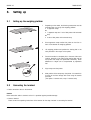
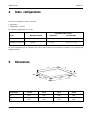
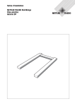
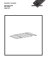
Installation information METTLER TOLEDO Floor scales Spider VLF FLOOR SCALES 1. SPIDER VLF General This installation information contains all necessary details regarding the setting up an putting into operation of the following weighing platforms: SPIDER VLF 600 / A SPIDER VLF 1500 / A Information regarding operation can be found in the operating instructions. Information regarding maintenance, rectification of malfunctions an repairs is contained in the service manual 22004315. 2. Installation 2.1 Selecting the location ▲ Never operate in hazardous areas or in the areas hazarded by gases, vapors, mists and dusts! The foundation at the installation site must be capable of safely supporting the weight of the weighing platform at the support points when it carries the maximum load. At the same time, it should be so stable that no vibrations occur during weighing operations. Ensure that vibrations due to machines near the installation site are kept to a minimum. Installation information 22004312A 02/2001 -1- SPIDER VLF FLOOR SCALES 3. Setting up 3.1 Setting up the weighing platform 1. Depending on the model, the following accessories must be available when you set up the weighing platform: 2 approach ramps or 1 approach ramp and 1 set of foot plates with horizontal stop or 2 sets of foot plates with horizontal stop 2. Place approach ramps and/or foot plates on the floor in front of and behind the weighing platform. 3. Lift weighing platform and position the leveling feet in the slots provided in the ramps or foot plates. 4. Ensure the surface is completely flat in the area of the scale location, especially in the region of the leveling feet, and the foot plates and ramps are positioned horizontally. Small differences in height can be compensated by adjustable feet. 5. Align ramps and foot plates. 6. Mark position of the ramps resp. foot plates. It is essential to fix them to the floor through drill holes using the dowels provided. (Foot plates: 2 dowels each, ramp: 2 dowels each) or or 3.2 Connecting the terminal Route connection cable to the terminal. Caution Route connection cable to terminal so that it is protected against possible damage. Connect terminal. Please consult the operating instructions of the terminal for the steps involved in connceting the terminal. - 2 - Installation information 22004312A 02/2001 FLOOR SCALES 4. SPIDER VLF Scale configurations The scale is configured ex factory as follows: approvable SingleRange 1 x 3000 e The following configurations can be set: Verification Scale Interval Type Maximum Capacity approvable non-approvable SPIDER VLF 600 / A 600 kg 0.2 kg 0.2 / 0.1 / 0.05 kg SPIDER VLF 1500 / A 1500 kg 0.5 kg 0.5 / 0.2 / 0.1 kg The scale configuration can be changed in the service mode. Please see the installation information of the corresponding weighing terminal. 5. Dimensions 00 15B 12A5 0 0 660 Ø50 A1-115 000 000 14B0-1 0 220 Dimensions VLF-DS VLF-D VLF-E VLF-ES A 1000 1000 1250 1500 B 1000 1250 1500 1500 Installation information 22004312A 02/2001 -3- *22004312* 22004312 Subject to technical changes © Mettler-Toledo (Albstadt) GmbH Mettler-Toledo (Albstadt) GmbH D-72458 Albstadt Tel. ++49-7431-14 0, Fax ++49-7431-14 232 Internet: http://www.mt.com 02/2001 Printed in Germany 22004312A