1
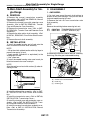
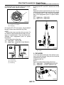
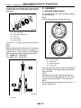
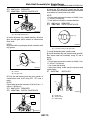
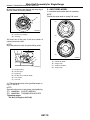
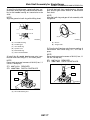
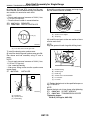
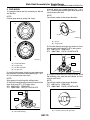
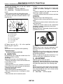
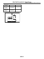
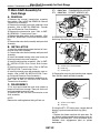
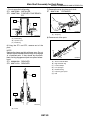
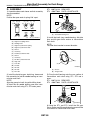
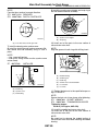
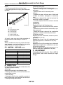
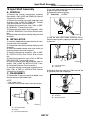
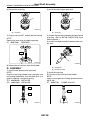
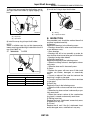
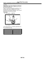
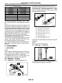
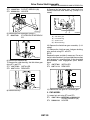
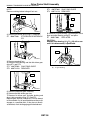
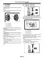
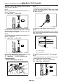
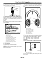
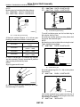
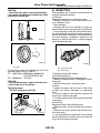
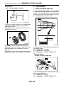
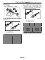
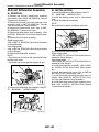
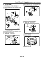
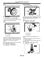
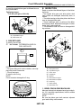
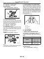
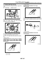
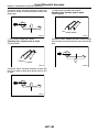
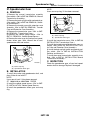
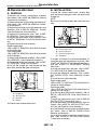
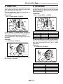
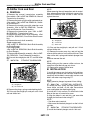
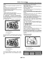
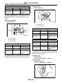
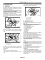
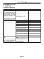
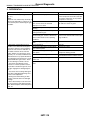
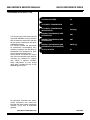
2004 IMPREZA SERVICE MANUAL
QUICK REFERENCE INDEX
TRANSMISSION SECTION
This service manual has been prepared
to provide SUBARU service personnel
with the necessary information and data
for the correct maintenance and repair
of SUBARU vehicles.
This manual includes the procedures
for maintenance, disassembling, reassembling, inspection and adjustment of
components and diagnostics for guidance of experienced mechanics.
Please peruse and utilize this manual
fully to ensure complete repair work for
satisfying our customers by keeping
their vehicle in optimum condition.
When replacement of parts during
repair work is needed, be sure to use
SUBARU genuine parts.
CONTROL SYSTEMS
CS
AUTOMATIC TRANSMISSION
4AT
AUTOMATIC TRANSMISSION
(DIAGNOSTICS)
4AT(diag)
MANUAL TRANSMISSION AND
DIFFERENTIAL
5MT
MANUAL TRANSMISSION AND
DIFFERENTIAL
6MT
MANUAL TRANSMISSION AND
DIFFERENTIAL (DIAGNOSTICS)
6MT(diag)
CLUTCH SYSTEM
CL
All information, illustration and specifications contained in this manual are
based on the latest product information
available at the time of publication
approval.
FUJI HEAVY INDUSTRIES LTD.
G1870GE4
MANUAL TRANSMISSION AND
DIFFERENTIAL
5MT
1.
2.
3.
4.
5.
6.
7.
8.
9.
10.
11.
12.
13.
14.
15.
16.
17.
18.
19.
20.
21.
22.
23.
24.
25.
Page
General Description ....................................................................................2
Transmission Gear Oil ..............................................................................37
Manual Transmission Assembly ...............................................................38
Transmission Mounting System ................................................................45
Oil Seal......................................................................................................47
Switches and Harness ..............................................................................48
Vehicle Speed Sensor...............................................................................51
Preparation for Overhaul...........................................................................52
Transfer Case and Extension Case Assembly..........................................53
Rear Case .................................................................................................57
Transfer Drive Gear ..................................................................................58
Transfer Driven Gear ................................................................................60
Center Differential .....................................................................................62
Reverse Check Sleeve..............................................................................63
Transmission Case ...................................................................................66
Main Shaft Assembly for Single-Range ....................................................72
Main Shaft Assembly for Dual-Range .......................................................82
Input Shaft Assembly ................................................................................87
Drive Pinion Shaft Assembly.....................................................................91
Front Differential Assembly .....................................................................102
Speedometer Gear..................................................................................109
Reverse Idler Gear..................................................................................110
Shifter Fork and Rod ...............................................................................112
Counter Gear ..........................................................................................115
General Diagnostic..................................................................................117
Main Shaft Assembly for Single-Range
MANUAL TRANSMISSION AND DIFFERENTIAL
16.Main Shaft Assembly for Single-Range
C: DISASSEMBLY
A: REMOVAL
1) Put vinyl tape around the main shaft splines to
protect oil seal from damage. Then pull out the oil
seal and needle bearing by hand.
2) Remove the lock nut from transmission main
shaft assembly.
1) Remove the manual transmission assembly
from vehicle. <Ref. to 5MT-38, REMOVAL, Manual
Transmission Assembly.>
2) Remove the transfer case with extension case
assembly. <Ref. to 5MT-53, REMOVAL, Transfer
Case and Extension Case Assembly.>
3) Remove the transmission case. <Ref. to 5MT53, REMOVAL, Transfer Case and Extension Case
Assembly.>
4) Remove the drive pinion shaft assembly. <Ref.
to 5MT-91, REMOVAL, Drive Pinion Shaft Assembly.>
5) Remove the main shaft assembly.
1. AWD MODEL
NOTE:
Remove the caulking before removing lock nut.
ST1 499987000 TRANSMISSION HOLDER
ST2 498937003 SOCKET WRENCH (35)
B: INSTALLATION
1) Install the needle bearing and oil seal onto the
front of transmission main shaft assembly.
NOTE:
• Wrap the clutch splined section with vinyl tape to
prevent damage to oil seal.
• Apply grease (Unilube #2 or equivalent) to the
sealing lip of oil seal.
• Use a new one.
2) Install the needle bearing outer race knock pin
hole into transmission case knock pin.
ST2
ST1
MT-00186
3) Remove the 5th-Rev sleeve and hub assembly,
baulk ring, 5th drive gear and needle bearing.
(C)
(B)
(A)
NOTE:
Align the end face of seal with surface (A) when installing oil seal.
MT-00187
(A) 5th-Rev sleeve and hub ASSY
(B) Baulk ring
(C) 5th drive gear
(A)
MT-00185
3) Install the drive pinion assembly. <Ref. to 5MT91, INSTALLATION, Drive Pinion Shaft Assembly.>
4) Install the transmission case. <Ref. to 5MT-68,
INSTALLATION, Transmission Case.>
5) Install the transfer case with extension case assembly. <Ref. to 5MT-53, INSTALLATION, Transfer Case and Extension Case Assembly.>
6) Install the manual transmission assembly to vehicle. <Ref. to 5MT-41, INSTALLATION, Manual
Transmission Assembly.>
5MT-72
Main Shaft Assembly for Single-Range
MANUAL TRANSMISSION AND DIFFERENTIAL
4) Remove the snap ring and synchro cone stopper
from 5th-Rev sleeve and hub assembly.
6) Using the ST1 and ST2, remove rest of the
parts.
NOTE:
Replace the sleeve and hub with new ones. Do not
attempt to disassemble because they must engage
at a specified point. If they should be disassembled, mark engagement point on splines beforehand.
ST1 899864100 REMOVER
ST2 899714110 REMOVER
(B)
(A)
(A)
MT-00188
(A) Synchro cone stopper
(B) Snap ring
ST1
5) Using the ST1, ST2 and a press, remove the ball
bearing, synchro cone and baulk ring (Rev).
NOTE:
• Replace the sleeve and hub with new ones. Do
not attempt to disassemble because they must engage at a specified point. If they should be disassembled, mark engagement point on splines
beforehand.
• Do not reuse the ball bearing.
ST1 499757002 INSTALLER
ST2 498077400 SYNCHRO CONE REMOVER
ST2
ST1
MT-00190
(B)
ST2
(A) Press
(A)
2. FWD MODEL
(C)
MT-00189
(A) Ball bearing
(B) Synchro cone
(C) Baulk ring
1) Put vinyl tape around main shaft splines to protect oil seal from damage. Then pull out oil seal and
needle bearing by hand.
2) Remove lock nut.
NOTE:
Remove caulking before taking off lock nut.
ST1 498937000 TRANSMISSION HOLDER
ST2 499987003 SOCKET WRENCH (35)
ST1
ST2
MT-00818
5MT-73
Main Shaft Assembly for Single-Range
MANUAL TRANSMISSION AND DIFFERENTIAL
3) Remove the insert stopper plate, sleeve and hub
assembly No. 2, baulk ring, 5th drive gear and needle bearing.
D: ASSEMBLY
1. AWD NON-TURBO MODEL
1) Assemble when each sleeve and hub assembly
are disassembled.
(A)
(B)
NOTE:
Position the open ends of spring 120° apart.
(C)
(D)
(E)
(A)
MT-00819
(A)
(B)
(C)
(D)
(E)
Insert stopper plate
Sleeve and hub ASSY No. 2
Baulk ring
5th drive gear
Needle bearing
(B)
(C)
4) Using ST1, ST2 and a press, remove the rest of
parts.
NOTE:
Replace sleeve and hub with ones. Do not attempt
to disassemble because they must engage at a
specified point. If they should be disassembled,
mark engagement point on splines before hand.
ST1 899864100 REMOVER
ST2 899714110 REMOVER
(D)
MT-00191
(A)
(B)
(C)
(D)
(A)
ST1
3rd-4th hub ASSY
3rd gear side
5th-Rev hub ASSY
5th gear side
2) Install the 3rd drive gear, baulk ring, sleeve and
hub assembly for 3rd needle bearing on transmission main shaft.
NOTE:
Align the groove in baulk ring with shifting insert.
3) Install the 4th needle bearing race onto transmission main shaft using ST1, ST2 and a press.
NOTE:
Do not apply pressure in excess of 10 kN (1 ton, 1.1
US ton, 1.0 Imp ton).
ST2
MT-00820
(A) Press
5MT-74
Main Shaft Assembly for Single-Range
MANUAL TRANSMISSION AND DIFFERENTIAL
ST1
ST2
899714110
499877000
REMOVER
RACE 4-5 INSTALLER
6) Using the ST1 and ST2, install the 5th gear
thrust washer and 5th needle bearing race onto the
rear section of transmission main shaft.
NOTE:
• Do not apply pressure in excess of 10 kN (1 ton,
1.1 US ton, 1.0 Imp ton).
• Face the thrust washer in correct direction.
ST1 899714110 REMOVER
ST2 499877000 RACE 4-5 INSTALLER
ST2
(A)
ST1
MT-00192
(A) 4th needle bearing race
(A)
4) Install the baulk ring, needle bearing, 4th drive
gear and 4th gear thrust washer to transmission
main shaft.
NOTE:
Align the baulk ring and gear & hub assembly with
key groove.
MT-00195
(A) Face this surface to 5th gear side.
7) Install the bearing onto synchro cone.
8) Install the baulk ring and synchro cone onto 5thRev sleeve and hub assembly using ST and a
press.
NOTE:
• Do not apply pressure in excess of 10 kN (1 ton,
1.1 US ton, 1.0 Imp ton).
• Use a new ball bearing.
• After press fitting, make sure the synchro cone
rotates freely.
ST 499757002
INSTALLER
(A)
(B)
MT-00193
(A) Groove
(B) 4th gear side
5) Drive the ball bearing onto the rear section of
transmission main shaft using ST1, ST2 and a
press.
NOTE:
Do not apply pressure in excess of 10 kN (1 ton, 1.1
US ton, 1.0 Imp ton).
ST1 899714110 REMOVER
ST2 499877000 RACE 4-5 INSTALLER
ST
(A)
(B)
MT-00196
(A) Baulk ring
(B) Synchro cone
(C) Ball bearing
ST2
ST1
MT-00194
5MT-75
(C)
Main Shaft Assembly for Single-Range
MANUAL TRANSMISSION AND DIFFERENTIAL
9) Install the synchro cone stopper and snap ring to
5th-Rev sleeve and hub assembly.
2. AWD TURBO MODEL
1) Assemble each sleeve and hub assembly.
NOTE:
Position the open ends of spring 120° apart.
(B)
(A)
(A)
MT-00188
(A) Synchro cone stopper
(B) Snap ring
(B)
10) Install rest of the parts to the rear section of
transmission main shaft.
(C)
NOTE:
Align the groove in baulk ring with shifting insert.
(A)
(B)
(C)
(D)
(D)
(E)
MT-00191
(F)
(A)
(B)
(C)
(D)
MT-00198
(A)
(B)
(C)
(D)
(E)
(F)
Needle bearing
5th drive gear
Baulk ring
5th-Rev sleeve and hub ASSY
Lock washer
Lock nuts
11) Tighten the lock nuts to the specified torque using ST1 and ST2.
NOTE:
Secure the lock nuts in two places after tightening.
ST1 499987003 SOCKET WRENCH
ST2 498937000 TRANSMISSION HOLDER
Tightening torque:
120 N·m (12.2 kgf-m, 88.5 ft-lb)
5MT-76
3rd-4th hub ASSY
3rd gear side
5th-Rev hub ASSY
5th gear side
Main Shaft Assembly for Single-Range
MANUAL TRANSMISSION AND DIFFERENTIAL
2) Install the 3rd drive gear, outer baulk ring, synchro cone, inner baulk ring, sleeve and hub assembly for 3rd needle bearing on transmission main
shaft.
NOTE:
Align the groove in baulk ring with shifting insert.
(A)
4) Install the baulk ring, needle bearing, 4th drive
gear and 4th gear thrust washer to transmission
main shaft.
NOTE:
Align the baulk ring and gear & hub assembly with
key groove.
(E)
(D)
(A)
(B)
(B)
(A)
(B)
(C)
(D)
(E)
(F)
(C)
(F)
MT-00200
MT-00193
3rd needle bearing
3rd drive gear
Inner baulk ring
Synchro cone
Outer baulk ring
Sleeve and hub ASSY
(A) Groove
(B) 4th gear side
5) Drive the ball bearing onto the rear section of
transmission main shaft using ST1, ST2 and a
press.
3) Install the 4th needle bearing race onto transmission main shaft using ST1, ST2 and a press.
NOTE:
Do not apply pressure in excess of 10 kN (1 ton, 1.1
US ton, 1.0 Imp ton).
ST1 899714110 REMOVER
ST2 499877000 RACE 4-5 INSTALLER
NOTE:
Do not apply pressure in excess of 10 kN (1 ton, 1.1
US ton, 1.0 Imp ton).
ST1 899714110 REMOVER
ST2 499877000 RACE 4-5 INSTALLER
ST2
ST2
ST1
(A)
ST1
MT-00194
MT-00192
(A) 4th needle bearing race
5MT-77
Main Shaft Assembly for Single-Range
MANUAL TRANSMISSION AND DIFFERENTIAL
6) Using the ST1 and ST2, install the 5th gear
thrust washer and 5th needle bearing race onto the
rear section of transmission main shaft.
9) Install the synchro cone stopper and snap ring to
5th-Rev sleeve and hub assembly.
(B)
NOTE:
• Do not apply pressure in excess of 10 kN (1 ton,
1.1 US ton, 1.0 Imp ton).
• Face the thrust washer in correct direction.
ST1 899714110 REMOVER
ST2 499877000 RACE 4-5 INSTALLER
(A)
MT-00188
(A) Synchro cone stopper
(B) Snap ring
(A)
10) Install the rest parts to the rear section of transmission main shaft.
NOTE:
Align the groove in baulk ring with shifting insert.
MT-00195
(A) Face this surface to 5th gear side.
(A)
(B)
(C)
(D)
7) Install the bearing onto synchro cone.
8) Install the baulk ring and synchro cone onto 5thRev sleeve and hub assembly using ST and a
press.
(E)
NOTE:
• Do not apply pressure in excess of 10 kN (1 ton,
1.1 US ton, 1.0 Imp ton).
• Use a new ball bearing.
• After press fitting, make sure the synchro cone
rotates freely.
ST 499757002
INSTALLER
(F)
MT-00198
(A)
(B)
(C)
(D)
(E)
(F)
ST
(A)
(B)
(C)
11) Tighten the lock nuts to the specified torque using ST1 and ST2.
MT-00196
(A) Baulk ring
(B) Synchro cone
(C) Ball bearing
Needle bearing
5th drive gear
Baulk ring
5th-Rev sleeve and hub ASSY
Lock washer
Lock nuts
NOTE:
Secure the lock nuts in two places after tightening.
ST1 499987003 SOCKET WRENCH
ST2 498937000 TRANSMISSION HOLDER
Tightening torque:
120 N·m (12.2 kgf-m, 88.5 ft-lb)
5MT-78
Main Shaft Assembly for Single-Range
MANUAL TRANSMISSION AND DIFFERENTIAL
3. FWD MODEL
1) Assemble sleeve and hub assembly for 3rd-4th
and 5th-Rev.
4) Install baulk ring, needle bearing (32 × 30 ×
25.7), 4th drive gear and 4th gear thrust washer to
transmission main shaft.
NOTE:
Face thrust washer in the correct direction.
NOTE:
Position open ends of spring 120° apart.
(A)
(A)
(B)
MT-00193
(B)
(A) Groove
(B) 4th gear side
(C)
5) Drive ball bearing onto the rear section of transmission main shaft using ST1, ST2 and a press.
ST1 899714110 REMOVER
ST2 499877000 RACE 4-5 INSTALLER
(D)
ST2
MT-00191
(A)
(B)
(C)
(D)
3rd-4th hub ASSY
3rd gear side
5th-Rev hub ASSY
5th gear side
ST1
2) Install 3rd drive gear, baulk ring and sleeve and
hub assembly for 3rd-4th needle bearing (32 × 36 ×
25.7) on transmission main shaft.
NOTE:
Align groove in baulk ring with shifting insert.
3) Install 4th needle bearing race onto transmission
main shaft using ST1, ST2 and a press.
ST1 899714110 REMOVER
ST2 499877000 RACE 4-5 INSTALLER
MT-00194
6) Using the same tools as in step 5) above, install
the following parts onto the rear section of transmission main shaft.
NOTE:
Face thrust washer in the correct direction.
ST1 899714110 REMOVER
ST2 499877000 RACE 4-5 INSTALLER
ST2
(A)
(A)
ST1
MT-00195
MT-00192
(A) Face this surface to 5th gear side.
(A) 4th needle bearing
5MT-79
Main Shaft Assembly for Single-Range
MANUAL TRANSMISSION AND DIFFERENTIAL
7) Install the following parts to the rear section
transmission main shaft.
ST1 499987003 SOCKET WRENCH
ST2 498937000 TRANSMISSION HOLDER
NOTE:
• Align groove in baulk ring with shifting insert.
• Be sure to fit pawl of insert stopper plate into 4
mm (0.16 in) dia. hole in the boss section of synchronizer hub.
(A)
(B)
(C)
(D)
(E)
(F)
(G)
3) Gears
• Replace the gears with new ones if their tooth
surfaces are broken, damaged, or excessively
worn.
• Correct or replace if the cone that contacts the
baulk ring is rough or damaged.
• Correct or replace if the inner surface or end face
is damaged.
4) Baulk ring
Replace the ring in the following cases:
• When the inner surface and end face are damaged.
• When the ring inner surface is abnormally or partially worn down.
• When the contact surface of the synchronizer
ring insert is scored or abnormally worn down.
5) Shifting insert key
Replace the insert if deformed, excessively worn,
or defective in any way.
MT-00821
(A)
(B)
(C)
(D)
(E)
(F)
(G)
Needle bearing
5th drive gear
Baulk ring
Sleeve and hub ASSY
Insert stopper plate
Lock washer
Lock nut
8) Tighten lock nuts (22 × 13) to the specified
torque using ST1 and ST2.
NOTE:
Secure lock nuts in two places after tightening.
Tightening torque:
120 N·m (12.2 kgf-m, 88.5 ft-lb)
E: INSPECTION
Disassembled parts should be washed clean first
and then inspected carefully.
1) Bearings
Replace the bearings in the following cases:
• Bearings whose balls, outer races and inner races are broken or rusty.
• Worn bearings
• Bearings that fail to turn smoothly or make abnormal noise when turned after gear oil lubrication.
• Bearings having other defects
2) Bushing (each gear)
Replace the bushing in the following cases:
• When the sliding surface is damaged or abnormally worn.
• When the inner wall is abnormally worn.
MT-00208
6) Oil seal
Replace the oil seal if the lip is deformed, hardened, damaged, worn, or defective in any way.
7) O-ring
Replace the O-ring if the sealing face is deformed,
hardened, damaged, worn, or defective in any way.
8) Gearshift mechanism
Repair or replace the gearshift mechanism if excessively worn, bent, or defective in any way.
F: ADJUSTMENT
Selection of main shaft rear plate:
Using the ST, measure the amount (A) of ball bearing protrusion from transmission main case surface
and select the proper plate in the following table:
NOTE:
Before measuring, tap the end of main shaft with a
plastic hammer lightly in order to make the clearance zero between the main case surface and the
moving flange of bearing.
ST 498147000
DEPTH GAUGE
5MT-80
Main Shaft Assembly for Single-Range
MANUAL TRANSMISSION AND DIFFERENTIAL
Dimension (A)
mm (in)
4.00 — 4.13
(0.1575 —
0.1626)
3.87 — 3.99
(0.1524 —
0.1571)
Part No.
Mark
32294AA041
1
32294AA051
2
(A)
MT-00209
5MT-81
Main Shaft Assembly for Dual-Range
MANUAL TRANSMISSION AND DIFFERENTIAL
17.Main Shaft Assembly for
Dual-Range
ST1
ST2
498937000
499987003
TRANSMISSION HOLDER
SOCKET WRENCH (35)
A: REMOVAL
1) Remove the manual transmission assembly
from vehicle. <Ref. to 5MT-38, REMOVAL, Manual
Transmission Assembly.>
2) Remove the transfer case with extension case
assembly. <Ref. to 5MT-53, REMOVAL, Transfer
Case and Extension Case Assembly.>
3) Remove the transmission case. <Ref. to 5MT66, REMOVAL, Transmission Case.>
4) Remove the drive pinion shaft assembly. <Ref.
to 5MT-91, REMOVAL, Drive Pinion Shaft Assembly.>
5) Remove the main shaft assembly and input shaft
assembly.
ST1
ST2
MT-00186
3) Remove the 5th-Rev sleeve and hub assembly,
baulk ring, 5th drive gear and needle bearing.
(C)
(B)
B: INSTALLATION
(A)
1) Install the needle bearing onto the front of transmission main shaft assembly.
2) Connect the main shaft assembly and input shaft
assembly.
3) Install the needle bearing outer race knock pin
hole into transmission case knock pin.
4) Install the drive pinion assembly. <Ref. to 5MT91, INSTALLATION, Drive Pinion Shaft Assembly.>
5) Install the transmission case. <Ref. to 5MT-68,
INSTALLATION, Transmission Case.>
6) Install the transfer case with extension case assembly. <Ref. to 5MT-53, INSTALLATION, Transfer Case and Extension Case Assembly.>
7) Install the manual transmission assembly to vehicle. <Ref. to 5MT-41, INSTALLATION, Manual
Transmission Assembly.>
MT-00187
(A) 5th-Rev sleeve and hub ASSY
(B) Baulk ring
(C) 5th drive gear
4) Remove the snap ring and synchro cone stopper
from 5th-Rev sleeve and hub assembly.
(B)
(A)
C: DISASSEMBLY
1) Put vinyl tape around the main shaft splines to
protect oil seal from damage. Then pull out the oil
seal and needle bearing by hand.
2) Remove the lock nut from transmission main
shaft assembly.
NOTE:
Remove the caulking before taking off lock nut.
MT-00188
(A) Synchro cone stopper
(B) Snap ring
5) Using the ST1, ST2 and a press, remove the ball
bearing, synchro cone and baulk ring (Rev).
NOTE:
• Replace the sleeve and hub with new ones. Do
not attempt to disassemble because they must engage at a specified point. If they should be disassembled, mark engagement point on splines
beforehand.
5MT-82
Main Shaft Assembly for Dual-Range
MANUAL TRANSMISSION AND DIFFERENTIAL
• Do not reuse the ball bearing.
ST1 499757002 INSTALLER
ST2 498077400 SYNCHRO CONE REMOVER
7) Remove the snap ring from main shaft.
ST 899474100
EXPANDER
ST1
(B)
ST2
(A)
ST
(C)
(A)
MT-00215
(A) Snap ring
MT-00189
8) Remove rest of the parts.
(A) Ball bearing
(B) Synchro cone
(C) Baulk ring
6) Using the ST1 and ST2, remove rest of the
parts.
NOTE:
Replace the sleeve and hub with new ones. Do not
attempt to disassemble because they must engage
at a specified point. If they should be disassembled, marking engagement point on splines beforehand.
ST1 899864100 REMOVER
ST2 899714110 REMOVER
(A)
ST1
ST2
MT-00190
(A) Press
5MT-83
(G)
(B)
(C)
(B)
(E)
(D)
(A)
(A)
(B)
(C)
(D)
(E)
(F)
(G)
Sleeve and hub ASSY
High-low baulk ring
Friction damper
Low input gear
Needle bearing
Input low gear spacer
Ball
(F)
MT-00216
Main Shaft Assembly for Dual-Range
MANUAL TRANSMISSION AND DIFFERENTIAL
D: ASSEMBLY
1) Assemble when each sleeve and hub assembly
are disassembled.
ST1
ST2
899714110
499877000
NOTE:
Position the open ends of spring 120° apart.
REMOVER
RACE 4-5 INSTALLER
ST2
(A)
(C)
(B) (A)
(F) (E)
(G)
(D)
(I)
(H)
ST1
(J)
MT-00201
(A) 4th needle bearing race
(K)
(A)
(B)
(C)
(D)
(E)
(F)
(G)
(H)
(I)
(J)
(K)
(L)
(M)
(N)
(O)
(P)
(L)
(M) (N)
(O) (P)
4) Install the baulk ring, needle bearing, 4th drive
gear and 4th gear thrust washer to transmission
main shaft.
MT-00217
High-low coupling sleeve
Shifting insert
High-low synchronizer spring
High-low synchronizer hub
Sleeve
Insert key
3rd-4th synchronizer hub
Sleeve
Insert key
5th-Rev synchronizer hub
High side
Low side
3rd side
4th side
5th side
Rev side
NOTE:
Face the thrust washer in correct direction.
(A)
(B)
MT-00193
(A) Groove
(B) 4th gear side
2) Install the 3rd drive gear, baulk ring, sleeve and
hub assembly for 3rd-4th needle bearing on transmission main shaft.
NOTE:
Align the groove in baulk ring with shifting insert.
3) Install the 4th needle bearing race onto transmission main shaft using ST1, ST2 and a press.
5) Drive the ball bearing onto the rear section of
transmission main shaft using ST1, ST2 and a
press.
ST1 899714110 REMOVER
ST2 499877000 RACE 4-5 INSTALLER
ST2
ST1
MT-00194
6) Using the ST1 and ST2, install the 5th gear
thrust washer and 5th needle bearing race onto the
rear section of transmission main shaft.
5MT-84
Main Shaft Assembly for Dual-Range
MANUAL TRANSMISSION AND DIFFERENTIAL
9) Install the synchro cone stopper and snap ring to
5th-Rev sleeve and hub assembly.
NOTE:
Face the thrust washer in correct direction.
ST1 899714110 REMOVER
ST2 499877000 RACE 4-5 INSTALLER
(B)
(A)
(A)
MT-00188
(A) Synchro cone stopper
(B) Snap ring
MT-00195
(A) Face this surface to 5th gear side.
7) Install the bearing onto synchro cone.
8) Install the baulk ring and synchro cone onto 5thRev sleeve and hub assembly using ST and a
press.
10) Install rest of the parts to the rear section of
transmission main shaft.
NOTE:
Align the groove in baulk ring with shifting insert.
(A)
NOTE:
• Use a new ball bearing.
• After press fitting, make sure the synchro cone
rotates freely.
ST 499757002
INSTALLER
(B)
(C)
(D)
(E)
(F)
ST
MT-00198
(A)
(B)
(C)
(A)
(B)
(C)
(D)
(E)
(F)
MT-00196
(A) Baulk ring
(B) Synchro cone
(C) Ball bearing
Needle bearing
5th drive gear
Baulk ring
5th-Rev sleeve and hub ASSY
Lock washer
Lock nuts
11) Tighten the lock nuts to the specified torque using ST1 and ST2.
NOTE:
Secure the lock nuts in two places after tightening.
ST1 499987003 SOCKET WRENCH
ST2 498937000 TRANSMISSION HOLDER
Tightening torque:
120 N·m (12.2 kgf-m, 88.5 ft-lb)
12) Install the needle bearing on main shaft.
13) Install rest of the parts to the front section of
transmission main shaft.
NOTE:
Be careful not to damage the graded section of
transmission main shaft when installing the needle
bearing.
5MT-85
Main Shaft Assembly for Dual-Range
MANUAL TRANSMISSION AND DIFFERENTIAL
NOTE:
• Face the grooved side toward input gear.
• Align the high-low baulk ring’s groove with shifting insert.
(A)
(F)
(E)
(F)
(C)
(D)
(G)
(A)
(B)
(C)
(D)
(E)
(F)
(G)
(B)
MT-00225
Ball
Input low gear spacer
Needle bearing
Low input gear
Friction damper
High-low baulk ring
Sleeve and hub ASSY
14) Install a new snap ring to the rod section of
transmission main shaft using ST1 and ST2.
NOTE:
Select a suitable outer snap ring so that axial clearance between snap ring and hub is held within
0.060 to 0.100 mm (0.0024 to 0.0039 in).
ST1 499757002 INSTALLER
ST2 499757001 SNAP RING GUIDE
Snap ring
Part No.
805025051
805025052
805025053
805025054
805025055
805025056
805025057
805025058
2) Bushing (each gear)
Replace the bushing in the following cases:
• When the sliding surface is damaged or abnormally worn.
• When the inner wall is abnormally worn.
3) Gears
• Replace the gears with new ones if their tooth
surfaces are broken, damaged, or excessively
worn.
• Correct or replace if the cone that contacts the
baulk ring is rough or damaged.
• Correct or replace if the inner surface or end face
is damaged.
4) Baulk ring
Replace the ring in the following cases:
• When the inner surface and end face are damaged.
• When the ring inner surface is abnormally or partially worn down.
• When the contact surface of the synchronizer
ring insert is scored or abnormally worn down.
5) Shifting insert key
Replace the insert if deformed, excessively worn,
or defective in any way.
6) Oil seal
Replace the oil seal if the lip is deformed, hardened, damaged, worn, or defective in any way.
7) O-ring
Replace the O-ring if the sealing face is deformed,
hardened, damaged, worn, or defective in any way.
8) Gearshift mechanism
Repair or replace the gearshift mechanism if excessively worn, bent, or defective in any way.
F: ADJUSTMENT
Thickness mm (in)
2.42 (0.0953)
2.47 (0.0972)
2.52 (0.0992)
2.57 (0.1012)
2.62 (0.1031)
2.67 (0.1051)
2.72 (0.1071)
2.37 (0.0933)
Choose the main shaft rear plate. <Ref. to 5MT-80,
ADJUSTMENT, Main Shaft Assembly for SingleRange.>
E: INSPECTION
Disassembled parts should be washed clean first
and then inspected carefully.
1) Bearings
Replace the bearings in the following cases:
• Bearings whose balls, outer races and inner races are broken or rusty.
• Worn bearings
• Bearings that fail to turn smoothly or make abnormal noise when turned after gear oil lubrication.
• Bearings having other defects
5MT-86
Input Shaft Assembly
MANUAL TRANSMISSION AND DIFFERENTIAL
18.Input Shaft Assembly
A: REMOVAL
1) Remove the manual transmission assembly
from vehicle. <Ref. to 5MT-38, REMOVAL, Manual
Transmission Assembly.>
2) Remove the transfer case with extension case
assembly. <Ref. to 5MT-53, REMOVAL, Transfer
Case and Extension Case Assembly.>
3) Remove the transmission case. <Ref. to 5MT66, REMOVAL, Transmission Case.>
4) Remove the drive pinion shaft assembly. <Ref.
to 5MT-91, REMOVAL, Drive Pinion Shaft Assembly.>
5) Remove the main shaft assembly and input shaft
assembly.
B: INSTALLATION
1) Install the needle bearing onto the front of transmission main shaft assembly.
2) Connect the main shaft assembly and input shaft
assembly.
3) Install the needle bearing outer race knock pin
hole into transmission case knock pin.
4) Install the drive pinion assembly. <Ref. to 5MT91, INSTALLATION, Drive Pinion Shaft Assembly.>
5) Install the transmission case. <Ref. to 5MT-68,
INSTALLATION, Transmission Case.>
6) Install the transfer case with extension case assembly. <Ref. to 5MT-53, INSTALLATION, Transfer Case and Extension Case Assembly.>
7) Install the manual transmission assembly on vehicle. <Ref. to 5MT-41, INSTALLATION, Manual
Transmission Assembly.>
2) Put vinyl tape around the input shaft splines to
protect oil seal from damage.
3) Remove the inner snap ring.
ST 398663600
PLIERS
ST
MT-00227
4) Hold the input shaft holder stationary and remove the input shaft by tapping its end with a plastic hammer.
(B)
(A)
MT-00228
(A) Input shaft holder
(B) Input shaft
5) Remove the outer snap ring. Then remove the
oil squeeze plate and straight pin.
C: DISASSEMBLY
1) Remove the O-ring from input shaft holder. Also,
remove the input shaft holder shim.
NOTE:
• Use a new O-ring.
• Number of shims used varies from zero to two.
(A)
(B)
(B)
(A)
MT-00229
(A) Snap ring
(B) Oil squeeze plate
(C)
MT-00226
(A) Input shaft holder
(B) O-ring
(C) Input shaft holder shim
5MT-87
Input Shaft Assembly
MANUAL TRANSMISSION AND DIFFERENTIAL
6) Remove the snap ring.
2) Install the snap ring on input shaft.
(A)
(A)
MT-00230
MT-00230
(A) Snap ring
(A) Snap ring
7) Using a press and ST, remove the ball bearing.
NOTE:
Remove the inner snap ring before pressing.
ST 498077000
REMOVER
3) Inspect the clearance between ball bearing and
snap ring. <Ref. to 5MT-89, INSPECTION, Input
Shaft Assembly.>
4) Install the straight pin and oil squeeze plate to input shaft.
ST
(A)
(B)
MT-00231
MT-00234
8) Remove the oil seal from input shaft holder.
(A) Straight pin
(B) Oil squeeze plate
D: ASSEMBLY
1) Install the ball bearing onto input shaft.
NOTE:
Place the snap ring between input shaft gear and
ball bearing beforehand. Use the table at 8) as a
guide in selecting a suitable snap ring.
ST1 899580100 INSTALLER
ST2 399513600 INSTALLER
5) Install the snap ring.
6) Drive the oil seal into input shaft holder.
NOTE:
Apply a coat of grease to sealing lips before installing oil seal.
ST 398507703
DUMMY COLLAR
ST1
ST
ST2
MT-00232
MT-00235
5MT-88
Input Shaft Assembly
MANUAL TRANSMISSION AND DIFFERENTIAL
7) Wind vinyl tape around the shaft splines and insert input shaft into holder by lightly tapping it by
hand.
9) Install the O-ring to input shaft holder.
(A)
(B)
(B)
MT-00238
(A)
(A) O-ring
(B) Input shaft holder
MT-00236
(A) Vinyl tape
(B) Input shaft
E: INSPECTION
8) Install the snap ring to input shaft holder.
NOTE:
Select a suitable snap ring so that clearance between snap ring and bearing is held within 0 to 0.12
mm (0 to 0.0047 in).
ST 398663600
PLIERS
ST
MT-00227
Snap ring
Part No.
805168020
805168030
805168040
Thickness mm (in)
1.84 (0.0724)
1.92 (0.0756)
2.00 (0.0787)
Disassembled parts should be washed clean first
and then inspected carefully.
1) Bearings
Replace the bearings in the following cases:
• Bearings whose balls, outer races and inner races are broken or rusty.
• Worn bearings
• Bearings that fail to turn smoothly or make abnormal noise when turned after gear oil lubrication.
• Bearings having other defects
2) Bushing (each gear)
Replace the bushing in the following cases:
• When the sliding surface is damaged or abnormally worn.
• When the inner wall is abnormally worn.
3) Gears
• Replace the gears with new ones if their tooth
surfaces are broken, damaged, or excessively
worn.
• Correct or replace if the cone that contacts the
baulk ring is rough or damaged.
• Correct or replace if the inner surface or end face
is damaged.
4) Baulk ring
Replace the ring in the following cases:
• When the inner surface and end face are damaged.
• When the ring inner surface is abnormally or partially worn down.
• When the contact surface of the synchronizer
ring insert is scored or abnormally worn down.
5) Shifting insert key
Replace the insert if deformed, excessively worn,
or defective in any way.
6) Oil seal
Replace the oil seal if the lip is deformed, hardened, damaged, worn, or defective in any way.
5MT-89
Input Shaft Assembly
MANUAL TRANSMISSION AND DIFFERENTIAL
7) O-ring
Replace the O-ring if the sealing face is deformed,
hardened, damaged, worn, or defective in any way.
8) Gearshift mechanism
Repair or replace the gearshift mechanism if excessively worn, bent, or defective in any way.
9) Measure the clearance between snap ring and
ball bearing using thickness gauge.
Clearance:
0 — 0.12 mm (0 — 0.0047 in)
(A)
MT-00239
(A) Snap ring
If the measurement is not within specification, select a suitable snap ring.
Snap ring
Part No.
805028050
805028060
805028070
Thickness mm (in)
2.48 (0.0976)
2.56 (0.1008)
2.64 (0.1039)
5MT-90
Drive Pinion Shaft Assembly
MANUAL TRANSMISSION AND DIFFERENTIAL
19.Drive Pinion Shaft Assembly
4) Inspection and adjustment of ST:
A: REMOVAL
NOTE:
• Loosen the two bolts and adjust so that the scale
indicates 0.5 correctly when the plate end and the
scale end are on the same level.
• Tighten the two bolts.
ST 499917500
DRIVE PINION GAUGE
ASSY
1) Remove the manual transmission assembly
from vehicle. <Ref. to 5MT-38, REMOVAL, Manual
Transmission Assembly.>
2) Remove the transfer case with extension case
assembly. <Ref. to 5MT-53, REMOVAL, Transfer
Case and Extension Case Assembly.>
3) Remove the transmission case. <Ref. to 5MT66, REMOVAL, Transmission Case.>
4) Remove the drive pinion shaft assembly.
(A)
NOTE:
Use a hammer handle, etc. to remove if too tight.
(A)
(B)
(B)
ST
MT-00242
(A) Plate
(B) Scale
MT-00161
(A) Main shaft assembly
(B) Drive pinion shaft assembly
B: INSTALLATION
1) Remove the differential assembly.
2) Alignment marks/numbers on hypoid gear set:
The upper number on drive pinion is the match
number for combining it with hypoid driven gear.
The lower number is for shim adjustment. If no lower number is shown, the value is zero. The number
on hypoid driven gear indicates a number for combination with drive pinion.
5) Position the ST by inserting the knock pin of ST
into the knock hole in transmission case.
ST 499917500
DRIVE PINION GAUGE
ASSY
6) Slide the drive pinion gauge scale with finger tip
and read the value at the point where it matches
with the end face of drive pinion.
ST 499917500
DRIVE PINION GAUGE
ASSY
ST
(A)
(1)
MT-00243
+0
.1
(1)
(A) Adjust clearance to zero without shim.
(2)
MT-00241
(1) Drive pinion
(2) Hypoid driven gear
3) Place the drive pinion shaft assembly on right
hand transmission main case without shim and
tighten the bearing mounting bolts.
7) The thickness of shim shall be determined by
adding the value indicated on drive pinion to the
value indicated on ST. (Add if the number on drive
pinion is prefixed by + and subtract if the number is
prefixed by −.)
ST 499917500
DRIVE PINION GAUGE
ASSY
8) Select one to three shims from the next table for
the value determined as described above and take
a shim thickness which is closest to the indicated
value.
5MT-91
Drive Pinion Shaft Assembly
MANUAL TRANSMISSION AND DIFFERENTIAL
2) Withdraw the drive pinion from driven shaft.
Remove the differential bevel gear sleeve, adjusting washer No. 1, adjusting washer No. 2, thrust
bearing, needle bearing, drive pinion collar, needle
bearing and thrust bearing.
Drive pinion shim
Part No.
Thickness mm (in)
32295AA031
0.150 (0.0059)
32295AA041
0.175 (0.0069)
32295AA051
0.200 (0.0079)
32295AA061
0.225 (0.0089)
32295AA071
0.250 (0.0098)
32295AA081
0.275 (0.0108)
32295AA091
0.300 (0.0118)
32295AA101
0.500 (0.0197)
(F)
(E)
(G)
(H)
9) Install the differential assembly. <Ref. to 5MT102, INSTALLATION, Front Differential Assembly.>
10) Set the transmission main shaft assembly and
drive pinion assembly in position. (So there is no
clearance between the two when moved all the way
to the front). Inspect the suitable 1st-2nd, 3rd-4th
and 5th shifter fork so that coupling sleeve and reverse driven gear are positioned in the center of
their synchronizing mechanisms. <Ref. to 5MT-99,
INSPECTION, Drive Pinion Shaft Assembly.>
11) Install the transmission case. <Ref. to 5MT-68,
INSTALLATION, Transmission Case.>
12) Install the transfer case with extension case assembly. <Ref. to 5MT-53, INSTALLATION, Transfer Case and Extension Case Assembly.>
13) Install the manual transmission assembly to vehicle. <Ref. to 5MT-38, Manual Transmission Assembly.>
C: DISASSEMBLY
(A)
(B)
(D)
(A)
(B)
(C)
(D)
(E)
(F)
(G)
(H)
(C)
MT-00245
Differential bevel gear sleeve
Washer No. 1 (25 × 37.5 × t)
Thrust bearing (25 × 37.5 × 3)
Washer No. 2 (25 × 37.5 × 4)
Needle bearing (25 × 30 × 20)
Drive pinion collar
Needle bearing (30 × 37 × 23)
Thrust bearing (33 × 50 × 3)
3) Remove the roller bearing and washer using ST
and press.
NOTE:
Do not reuse the roller bearing.
ST 498077000
REMOVER
1. AWD MODEL
NOTE:
Attach a cloth to the end of driven shaft (on the frictional side of thrust needle bearing) to prevent
damage during disassembly or reassembly.
1) Straighten the lock nut at staked portion. Remove the lock nut using ST1, ST2 and ST3.
ST1 899884100 HOLDER
ST2 498427100 STOPPER
ST3 899988608 SOCKET WRENCH (27)
ST
MT-00246
4) Straighten the lock nut at staked portion. Remove the lock nut using ST1 and ST2.
ST1
ST2
ST3
MT-00244
5MT-92
Drive Pinion Shaft Assembly
MANUAL TRANSMISSION AND DIFFERENTIAL
ST1
ST2
499987300
899884100
ST2
SOCKET WRENCH (50)
HOLDER
9) Remove the 2nd driven gear, inner baulk ring,
synchro cone and outer baulk ring. (Except 1.6 L
model)
ST1
(D)
MT-00247
(C)
5) Remove the 5th driven gear using ST.
ST 499857000
5TH DRIVEN GEAR REMOVER
(A)
(B)
(C)
(D)
(A)
(B)
MT-00250
2nd driven gear
Inner baulk ring
Synchro cone
Outer baulk ring
10) Remove the 2nd driven gear assembly. (1.6 L
model)
11) Remove the 1st driven gear, 2nd gear bushing,
gear and hub using ST1 and ST2.
ST
MT-00248
6) Remove the woodruff key.
7) Remove the roller bearing, 3rd-4th driven gear
using ST1 and ST2.
ST1 499757002 INSTALLER
ST2 899714110 REMOVER
NOTE:
Replace the gear and hub if necessary. Do not attempt to disassemble if at all possible because they
must engage at a specified point. If they should be
disassembled, mark engagement point beforehand.
ST1 499757002 INSTALLER
ST2 899714110 REMOVER
ST1
ST1
ST2
ST2
MT-00251
MT-00249
8) Remove the key.
12) Remove the sub gear for 1st driven gear.
2. FWD MODEL
1) Loosen lock nut using ST1 and ST2.
ST1 49987100 or 499987003 or 899984103
SOCKETWRENCH (35)
ST2 899884100 HOLDER
5MT-93
Drive Pinion Shaft Assembly
MANUAL TRANSMISSION AND DIFFERENTIAL
ST1
ST2
NOTE:
Remove caulking before taking off lock nut.
ST2
499757002
899714110
SNAP RING GUIDE
REMOVER
ST1
ST1
ST2
MT-00825
MT-00822
2) Remove 5th driven gear using ST and press.
ST 498077000
5TH DRIVEN GEAR REMOVER
8) Remove 1st gear bushing, 1st driven gear thrust
plate and roller bearing using ST and press.
ST 498517000
REPLACER
CAUTION:
Replace roller bearing (41 × 71 × 23) with a new
one if this disassembly is performed.
ST
(A)
ST
MT-00823
3) Remove woodruff key.
4) Remove roller bearing and 3rd-4th driven gear
using ST1 and ST2.
ST1 499757002 SNAP RING GUIDE
ST2 899714110 REMOVER
ST1
ST2
MT-00824
5) Remove 2nd driven gear assembly.
6) Remove 3rd-4th driven gear key.
7) Remove 1st driven gear, 2nd gear bushing and
gear & hub assembly using ST1 and ST2.
Replace gear and hub if necessary. Do not attempt
to disassemble if at all possible because they must
engage at a specified point. If they have to be disassembled, mark the engaging point beforehand.
5MT-94
MT-00826
(A) 1st gear bushing
Drive Pinion Shaft Assembly
MANUAL TRANSMISSION AND DIFFERENTIAL
D: ASSEMBLY
ST1
ST2
1. AWD MODEL
499277200
499587000
INSTALLER
INSTALLER
1) Install the sleeve and hub assembly by matching
alignment marks.
ST1
NOTE:
Use a new gear and hub assembly, if gear or hub
have been replaced.
ST2
(B)
(A)
MT-00253
(C)
5) Install the 2nd driven gear, inner baulk ring, synchro cone, outer baulk ring and insert onto driven
shaft. (Except 1.6 L model)
(D)
(A)
(D)
MT-00252
(A)
(B)
(C)
(D)
1st gear side
2nd gear side
Flush surface
Stepped surface
2) Install the washer, snap ring and sub gear to 1st
driven gear.
3) Install the 1st driven gear, 1st baulk ring, gear
and hub assembly onto driven shaft.
NOTE:
• Take care to install the gear and hub assembly in
proper direction.
• Align the baulk ring and gear & hub assembly
with key groove.
4) Install the 2nd driven gear bushing onto driven
shaft using ST1, ST2 and press.
NOTE:
• Do not apply pressure in excess of 10 kN (1 ton,
1.1 US ton, 1.0 Imp ton).
• Attach a cloth to the end of driven shaft to prevent damage.
• When press fitting, align the oil holes of shaft and
bush.
(C)
(A)
(B)
(C)
(D)
(B)
MT-00254
2nd driven gear
Inner baulk ring
Synchro cone
Outer baulk ring
6) Install the 2nd driven gear, 1st-2nd bulk ring and
insert onto driven shaft. (1.6 L model)
7) After installing the key on driven shaft, install the
3rd-4th driven gear using ST and press.
NOTE:
• Do not apply pressure in excess of 10 kN (1 ton,
1.1 US ton, 1.0 Imp ton).
• Align the groove in baulk ring with insert.
ST 499277200
INSTALLER
ST
MT-00255
5MT-95
Drive Pinion Shaft Assembly
MANUAL TRANSMISSION AND DIFFERENTIAL
8) Install a set of roller bearings onto the driven
shaft using ST and press.
NOTE:
Do not apply pressure in excess of 10 kN (1 ton, 1.1
US ton, 1.0 Imp ton).
ST 499277200
INSTALLER
NOTE:
• Stake the lock nut at two points.
• Using the spring balancer, check that starting
torque of roller bearing is 0.1 to 1.5 N (0.01 to 0.15
kgf, 0.02 to 0.33 ft).
ST
MT-00259
MT-00256
11) Install the roller bearing onto drive pinion.
9) Position the woodruff key in groove on the rear
of driven shaft. Install the 5th driven gear onto driven shaft using ST and press.
NOTE:
Do not apply pressure in excess of 10 kN (1 ton, 1.1
US ton, 1.0 Imp ton).
ST 499277200
INSTALLER
NOTE:
When installing the roller bearing, note its directions (front and rear) because the knock pin hole in
outer race is offset.
(A)
ST
(B)
(A) Roller bearing
(B) Knock pin hole
MT-00257
10) Install the lock washer. Install the lock nut and
tighten to the specified torque using ST.
ST 499987300
SOCKET WRENCH (50)
Tightening torque:
260 N·m (26.5 kgf-m, 191.7 ft-lb)
MT-00260
12) Install the washer using ST1, ST2 and press.
NOTE:
• Discard the old lock nuts, replace with new ones.
• Secure the lock nut in four places.
ST1 499277100 BUSH 1-2 INSTALLER
ST2 499277200 INSTALLER
ST
ST2
ST1
(A)
MT-00258
MT-00261
(A) Washer
5MT-96
Drive Pinion Shaft Assembly
MANUAL TRANSMISSION AND DIFFERENTIAL
13) Install the thrust bearing and needle bearing.
Install the driven shaft assembly.
• Be sure the insert keys are correctly located in
the insert key grooves inside the reverse driven
gear.
(B)
(A)
MT-00262
14) Install the drive pinion collar, needle bearing,
adjusting washer No. 2, thrust bearing, adjusting
washer No. 1 and differential bevel gear sleeve in
that order.
(C)
(D)
NOTE:
Be careful because the spacer must be installed in
proper direction.
(E)
(F)
(A) (B)
MT-00827
(A)
(B)
(C)
(D)
(E)
(F)
(C) (D) (E) (F) (G) (H)
MT-00263
(A)
(B)
(C)
(D)
(E)
(F)
(G)
(H)
Driven shaft
Drive shaft
Drive pinion collar
Needle bearing (25 × 30 × 20)
Washer No. 2 (25 × 36 × 4)
Thrust bearing (25 × 37.5 × 3)
Washer No. 1 (25 × 36 × t)
Differential bevel gear sleeve
Key grooves
Reverse driven gear
1st driven gear side
2nd driven gear side
Flush surface
Stepped surface
2) Drive roller bearing onto drive pinion shaft and
1st driven gear thrust washer using ST1 and ST2.
ST1 499277000 RACE 4-5 INSTALLER
ST2 499277100 BUSH 1-2 INSTALLER
CAUTION:
Use new roller bearing, 1st gear thrust washer.
2. FWD MODEL
1) Assemble gear and hub assembly.
ST1
NOTE:
• Use new gear and hub assembly, if gear or hub
have been replaced.
ST2
(A)
MT-00828
(A) Thrust washer
3) Install 1st-2nd driven gear bushing onto drive
pinion shaft.
5MT-97
Drive Pinion Shaft Assembly
MANUAL TRANSMISSION AND DIFFERENTIAL
ST1
ST2
NOTE:
Bushing may be installed with either side up.
ST1 499877000 RACE 4-5 INSTALLER
ST2 499277100 BUSH 1-2 INSTALLER
499877000
499277100
RACE 4-5 INSTALLER
BUSH 1-2 INSTALLER
ST1
ST2
ST1
(A)
ST2
(A)
MT-00831
(A) 1st-2nd driven gear bushing
MT-00829
(A) 1st-2nd driven gear bushing
4) Measure outside diameter of 1st driven gear
bushing to determine suitable 1st driven gear.
Part number
32231AA841
32231AA851
32231AA861
1st driven gear
Outer diameter of bushing
mm (in)
42.019 — 42.033
(1.6543 — 1.6548)
42.005 — 42.018
(1.6537 — 1.6543)
41.990 — 42.004
(1.6531 — 1.6537)
7) Install 2nd driven gear and 1st-2nd balk ring to
drive pinion shaft by hand.
8) Install key into the groove on drive pinion shaft
and install 3rd-4th driven gear.
NOTE:
Ball bearing may be installed without using the tool.
There should be no problem.
ST 499877000
RACE 4-5 INSTALLER
ST
(A)
5) Install 1st driven gear, 1st-2nd balk ring and gear
and hub assembly (already assembled in previous
step) to drive pinion shaft by hand.
NOTE:
Align ring groove with insert.
MT-00832
(A) 3rd-4th driven gear
9) Install ball bearing (29 × 74 × 38) on drive pinion
shaft with ST.
ST 499277100
BUSH 1-2 INSTALLER
ST
MT-00830
6) Install 1st-2nd driven gear bushing to drive pinion shaft using ST1 and ST2.
MT-00833
10) Position woodruff key in groove on the rear of
drive pinion shaft. Install 5th driven gear onto drive
shaft using ST and press.
ST 499277100
INSTALLER
5MT-98
Drive Pinion Shaft Assembly
MANUAL TRANSMISSION AND DIFFERENTIAL
CAUTION:
• Face 5th driven gear in the correct direction.
• Be careful not to dislocate woodruff key while
installing 5th driven gear.
ST
MT-00834
E: INSPECTION
Disassembled parts should be washed clean first
and then inspected carefully.
1) Bearings
Replace the bearings in the following cases:
• Bearings whose balls, outer races and inner races are broken or rusty.
• Worn bearings
• Bearings that fail to turn smoothly or make abnormal noise when turned after gear oil lubrication.
• The ball bearing on the rear side of the drive pinion shaft should be checked for smooth rotation before the drive pinion assembly is disassembled. In
this case, because a preload is working on the
bearing, its rotation feels like it is slightly dragging
unlike the other bearings.
(A)
(A)
(B)
MT-00835
MT-00264
(A) Rear
11) Install lock washer and tighten lock nut to the
specified torque using ST1 and ST2.
ST1 49987100 or 499987003 or 899984103
SOCKETWRENCH (35)
ST2 899884100 HOLDER
CAUTION:
• Discard old lock nuts, replace with new ones.
• Secure lock nut in four places.
Tightening torque:
120 N·m (12.2 kgf-m, 88.5 ft-lb)
ST2
ST1
MT-00822
(A) Drive pinion shaft
(B) Ball bearing
• Bearings having other defects
2) Bushing (each gear)
Replace the bushing in the following cases:
• When the sliding surface is damaged or abnormally worn.
• When the inner wall is abnormally worn.
3) Gears
• Replace the gears with new ones if their tooth
surfaces are broken, damaged, or excessively
worn.
• Correct or replace if the cone that contacts the
baulk ring is rough or damaged.
• Correct or replace if the inner surface or end face
is damaged.
4) Baulk ring
Replace the ring in the following cases:
• When the inner surface and end face are damaged.
• When the ring inner surface is abnormally or partially worn down.
• If the gap between the end faces of the ring and
the gear splined part is excessively small when the
ring is pressed against the cone.
5MT-99
Drive Pinion Shaft Assembly
MANUAL TRANSMISSION AND DIFFERENTIAL
F: ADJUSTMENT
Clearance (A):
0.5 — 1.0 mm (0.020 — 0.040 in)
1. THRUST BEARING PRELOAD
1) After completing the preceding steps 1) through
3), select the adjusting washer No. 1 so that dimension (H) is zero through visual check. Position the
washer (18.3 × 30 × 4) and lock washer (18 × 30 ×
2) and install the lock nut (18 × 13.5).
(A)
MT-00265
• When the contact surface of the synchronizer
ring insert is scored or abnormally worn down.
5) Shifting insert key
Replace the insert if deformed, excessively worn,
or defective in any way.
(H)
MT-00208
6) Oil seal
Replace the oil seal if the lip is deformed, hardened, damaged, worn, or defective in any way.
7) O-ring
Replace the O-ring if the sealing face is deformed,
hardened, damaged, worn, or defective in any way.
MT-00267
2) Using the ST1, ST2 and ST3, tighten the lock nut
to specified torque.
ST1 899884100 HOLDER
ST2 498427100 STOPPER
ST3 899988608 SOCKET WRENCH (27)
Tightening torque:
120 N·m (12.2 kgf-m, 88.5 ft-lb)
ST1
ST2
ST3
MT-00268
3) After removing the ST2, measure the starting
torque using torque driver.
ST1 899884100 HOLDER
ST3 899988608 SOCKET WRENCH (27)
5MT-100
Drive Pinion Shaft Assembly
MANUAL TRANSMISSION AND DIFFERENTIAL
Starting torque:
0.3 — 0.8 N·m
(0.03 — 0.08 kgf-m, 0.2 — 0.6 ft-lb)
5) If the specified starting torque range cannot be
obtained when a No. 1 adjusting washer is used,
then select a suitable No. 2 adjusting washer from
those listed in the following table. Repeat steps 1)
through 4) to adjust starting torque.
ST1
ST3
MT-00269
(A)
(B)
4) If the starting torque is not within specified limit,
select a new adjusting washer No. 1 and recheck
starting torque.
(A) Adjusting washer No. 1
(B) Adjusting washer No. 2
Starting torque
Low
High
MT-00270
(A) Adjusting washer No. 1
(B) Adjusting washer No. 2
Dimension H
Small
Large
Washer No. 2
Select thicker one.
Select thinner one.
Adjusting washer No. 2
Part No.
Thickness mm (in)
803025059
3.850 (0.1516)
803025054
4.000 (0.1575)
803025058
4.150 (0.1634)
(A)
(B)
MT-00270
6) Recheck that the starting torque is within specified range, then clinch the lock nut at four positions.
Adjusting washer No. 1
Part No.
Thickness mm (in)
803025051
3.925 (0.1545)
803025052
3.950 (0.1555)
803025053
3.975 (0.1565)
803025054
4.000 (0.1575)
803025055
4.025 (0.1585)
803025056
4.050 (0.1594)
803025057
4.075 (0.1604)
5MT-101
Front Differential Assembly
MANUAL TRANSMISSION AND DIFFERENTIAL
20.Front Differential Assembly
B: INSTALLATION
A: REMOVAL
1) Install the differential side retainers using ST.
ST 499787000
WRENCH ASSY
2) Install the bearing outer race to transmission
case.
3) Install the differential assembly.
1) Remove the manual transmission assembly
from vehicle. <Ref. to 5MT-38, REMOVAL, Manual
Transmission Assembly.>
2) Remove the transfer case with extension case
assembly. <Ref. to 5MT-53, REMOVAL, Transfer
Case and Extension Case Assembly.>
3) Remove the transmission case. <Ref. to 5MT66, REMOVAL, Transmission Case.>
4) Remove the drive pinion shaft assembly. <Ref.
to 5MT-91, REMOVAL, Drive Pinion Shaft Assembly.>
5) Remove the main shaft assembly.
Single-range model
<Ref. to 5MT-72, REMOVAL, Main Shaft Assembly
for Single-Range.>
Dual-range model
<Ref. to 5MT-82, REMOVAL, Main Shaft Assembly
for Dual-Range.>
6) Remove the differential assembly.
NOTE:
• Be careful not to confuse the right and left roller
bearing outer races.
• Be careful not to damage the retainer oil seal.
MT-00162
7) Remove the differential side retainers using ST.
ST 499787000
WRENCH ASSY
NOTE:
Be careful not to fold the sealing lip of oil seal.
MT-00162
4) Install the main shaft assembly.
Single-range model
<Ref. to 5MT-72, INSTALLATION, Main Shaft Assembly for Single-Range.>
Dual-range model
<Ref. to 5MT-82, INSTALLATION, Main Shaft Assembly for Dual-Range.>
5) Install the drive pinion assembly. <Ref. to 5MT91, INSTALLATION, Drive Pinion Shaft Assembly.>
6) Install the transmission case. <Ref. to 5MT-68,
INSTALLATION, Transmission Case.>
7) Install the transfer case with extension case assembly. <Ref. to 5MT-53, INSTALLATION, Transfer Case and Extension Case Assembly.>
8) Install the manual transmission assembly to vehicle. <Ref. to 5MT-41, INSTALLATION, Manual
Transmission Assembly.>
ST
MT-00176
5MT-102
Front Differential Assembly
MANUAL TRANSMISSION AND DIFFERENTIAL
C: DISASSEMBLY
3) Pull out the pinion shaft, and remove the differential bevel pinion and gear and washer.
1. DIFFERENTIAL CASE ASSEMBLY
(B)
(D)
1) Loosen the twelve bolts and remove the hypoid
driven gear.
(C)
(A)
(C)
(D)
(B)
(A)
MT-00277
(A)
(B)
(C)
(D)
Pinion shaft
Bevel pinion
Bevel gear
Washer
4) Remove the roller bearing using ST.
ST 399527700
PULLER SET
MT-00275
ST
(A) Hypoid driven gear
2) Drive out the straight pin from differential assembly toward hypoid driven gear.
ST 899904100
REMOVER
MT-00278
2. SIDE RETAINER
1) Remove the O-ring.
ST
MT-00276
MT-00279
2) Remove the oil seal.
5MT-103
Front Differential Assembly
MANUAL TRANSMISSION AND DIFFERENTIAL
NOTE:
Do not reuse the oil seal. Prepare a new oil seal.
Standard backlash:
0.13 — 0.18 mm (0.0051 — 0.0071 in)
ST2
ST1
MT-00285
AT-00220
3) Align the pinion shaft and differential case at
their holes, and drive the straight pin into holes
from the hypoid driven gear side, using ST.
D: ASSEMBLY
1. DIFFERENTIAL CASE ASSEMBLY
1) Install the bevel gear and bevel pinion together
with washers, and insert pinion shaft.
NOTE:
Face the chamfered side of washer toward gear.
NOTE:
Lock the straight pin after installing.
ST 899904100
REMOVER
(A)
(C)
(B)
(B)
(A)
MT-00286
(C)
MT-00284
(A) Pinion shaft
(B) Differential case
(C) Straight pin
(A) Bevel pinion
(B) Bevel gear
(C) Pinion shaft
4) Install the roller bearing to differential case.
2) Measure the backlash between bevel gear and
pinion. If it is not within specifications, install a suitable washer to adjust it. <Ref. to 5MT-106, ADJUSTMENT, Front Differential Assembly.>
NOTE:
Be sure the pinion gear tooth contacts adjacent
gear teeth during measurement.
ST1 498247001 MAGNET BASE
ST2 498247100 DIAL GAUGE
NOTE:
• Do not apply pressure in excess of 10 kN (1 ton,
1.1 US ton, 1.0 Imp ton).
• Be careful because the roller bearing outer races
are used as a set.
ST1 499277100 BUSH 1-2 INSTALLER
ST2 398497701 ADAPTER
ST1
ST2
MT-00287
5MT-104
Front Differential Assembly
MANUAL TRANSMISSION AND DIFFERENTIAL
5) Install the hypoid driven gear to differential case
using twelve bolts.
Tightening torque:
T: 62 N·m (6.3 kgf-m, 45.6 ft-lb)
(A)
E: INSPECTION
Repair or replace the differential gear in the following cases:
• The hypoid drive gear and drive pinion shaft
tooth surface are damaged, excessively worn, or
seized.
• The roller bearing on the drive pinion shaft has a
worn or damaged roller path.
• There is damage, wear, or seizure of the differential bevel pinion, differential bevel gear, washer,
pinion shaft, and straight pin.
• The differential case has worn or damaged sliding surfaces.
T
(B)
MT-00288
(A)
(A) Hypoid driven gear
(B) Differential case
(G)
(E)
(F)
2. SIDE RETAINER
(H)
1) Install a new oil seal.
ST 18675AA000 DIFFERENTIAL SIDE OIL
SEAL INSTALLER
(F)
(E)
(I)
(B)
(C)
(G)
(D)
ST
(J)
(I)
MT-00289
MT-00814
NOTE:
• For press-fitting of oil seal to retainer, make tapping with plastic hammer etc.
• Do not use press.
2) Install a new O-ring.
(A)
(B)
(C)
(D)
(E)
(F)
(G)
(H)
(I)
(J)
NOTE:
Do not stretch or damage the O-ring.
Drive pinion shaft
Hypoid driven gear
Pinion shaft
Straight pin
Washer
Differential bevel gear
Differential bevel pinion
Snap ring
Roller bearing
Differential case
1. BEVEL PINION GEAR BACKLASH
Measure the backlash between bevel gear and pinion. If it is not within specifications, install a suitable
washer to adjust it.
MT-00279
NOTE:
Be sure the pinion gear tooth contacts adjacent
gear teeth during measurement.
5MT-105
Front Differential Assembly
MANUAL TRANSMISSION AND DIFFERENTIAL
ST1
ST2
498247001
498247100
3. TOOTH CONTACT OF HYPOID GEAR
MAGNET BASE
DIAL GAUGE
Check the tooth contact of hypoid gear as follows:
Apply a uniform thin coat of red lead on both tooth
surfaces of 3 or 4 teeth of the hypoid gear. Move
the hypoid gear back and forth by turning the transmission main shaft until a definite contact pattern is
developed on hypoid gear, and judge whether face
contact is correct. If it is inaccurate, make adjustment. <Ref. to 5MT-106, ADJUSTMENT, Front Differential Assembly.>
• Tooth contact is correct.
Standard backlash:
0.13 — 0.18 mm (0.0051 — 0.0071 in)
ST2
(A)
ST1
MT-00285
2. HYPOID GEAR BACKLASH
1) Set the ST1, ST2 and ST3. Insert the needle
through transmission oil drain plug hole so that the
needle comes in contact with the tooth surface at a
right angle and check the backlash.
ST1 498247001 MAGNET BASE
ST2 498247100 DIAL GAUGE
ST3 498255400 PLATE
2) Install the SUBARU genuine axle shafts to both
side, rotate in the inversion direction so that the
gauge contact with the tooth surface and read the
dial gauge.
Part No. 38415AA100 AXLE SHAFT
(A)
(B)
(C)
(D)
(C)
(B)
MT-00294
Toe
Coast side
Heel
Drive side
F: ADJUSTMENT
1. BEVEL PINION GEAR BACKLASH
Backlash:
0.13 — 0.18 mm (0.0051 — 0.0071 in)
ST3
(D)
1) Disassemble the front differential. <Ref. to 5MT102, REMOVAL, Front Differential Assembly.>
2) Select a differential washer from the table and
install.
Washer
ST2
Part No.
803038021
803038022
ST1
MT-00293
803038023
NOTE:
If the backlash is outside specified range, adjust it
by turning the holder in right side case.
Thickness mm (in)
0.925 — 0.950
(0.0364 — 0.0374)
0.975 — 1.000
(0.0384 — 0.0394)
1.025 — 1.050
(0.0404 — 0.0413)
3) Adjust until the specified value is obtained.
Standard backlash:
0.13 — 0.18 mm (0.0051 — 0.0071 in)
5MT-106
Front Differential Assembly
MANUAL TRANSMISSION AND DIFFERENTIAL
2. HYPOID GEAR BACKLASH
Adjust backlash by turning the holder in right side
case.
ST 499787000
WRENCH ASSY
• Face contact
Checking item: Backlash is too large.
Contact pattern
ST
AT-00208
MT-00176
NOTE:
Each time holder rotates one tooth, backlash
changes by 0.05 mm (0.0020 in).
Corrective action: Reduce thickness of drive pinion
shim in order to bring drive pinion close to driven
gear.
0.05mm(0.0020 in)
AT-00212
• Flank contact
Checking item: Backlash is too small.
Contact pattern
MT-00296
3. TOOTH CONTACT OF HYPOID GEAR
1) Adjust until the tooth contact is correct.
2) Check and adjust the tooth contact with following.
• Tooth contact
Checking item:Tooth contact pattern is slightly
shifted toward to toe side under no-load
rotation. [When loaded, contact pattern moves
toward heel.]
AT-00209
(A)
(B)
AT-00207
(A) Toe side
(B) Heel side
5MT-107
Front Differential Assembly
MANUAL TRANSMISSION AND DIFFERENTIAL
Corrective action: Increase thickness of drive pinion shim in order to move drive pinion away from
driven gear.
• Heel contact (Outside end contact)
Checking item: Contact areas is small.
Contact pattern
AT-00213
AT-00211
• Toe contact (Inside end contact)
Checking item: Contact areas is small.
Contact pattern
Corrective action: Reduce thickness of drive pinion
shim in order to move drive pinion away from driven
gear.
AT-00210
AT-00212
Corrective action: Increase thickness of drive pinion shim in order to bring drive pinion close to driven gear.
AT-00213
5MT-108
Speedometer Gear
MANUAL TRANSMISSION AND DIFFERENTIAL
21.Speedometer Gear
NOTE:
Use a new snap ring, if it has been removed.
A: REMOVAL
1) Remove the manual transmission assembly
from vehicle. <Ref. to 5MT-38, REMOVAL, Manual
Transmission Assembly.>
2) Remove the back-up light switch and neutral position switch. <Ref. to 5MT-48, REMOVAL, Switches and Harness.>
3) Remove the transfer case with extension case
assembly. <Ref. to 5MT-53, REMOVAL, Transfer
Case and Extension Case Assembly.>
4) Remove the transmission case. <Ref. to 5MT66, REMOVAL, Transmission Case.>
5) Remove the vehicle speed sensor. <Ref. to
5MT-51, REMOVAL, Vehicle Speed Sensor.>
6) Remove the outer snap ring and pull out speedometer driven gear. Next, remove the oil seal,
speedometer shaft and washer.
(A)
(B)
(A)
(B)
MT-00301
(A) Outer snap ring
(B) Speedometer driven gear
4) Install the transmission case. <Ref. to 5MT-68,
INSTALLATION, Transmission Case.>
5) Install the transfer case with extension case assembly. <Ref. to 5MT-53, INSTALLATION, Transfer Case and Extension Case Assembly.>
6) Install the back-up light switch and neutral position switch. <Ref. to 5MT-49, INSTALLATION,
Switches and Harness.>
7) Install the manual transmission assembly to vehicle. <Ref. to 5MT-41, INSTALLATION, Manual
Transmission Assembly.>
C: INSPECTION
MT-00301
Check the speedometer gear, oil seal and speedometer shaft for damage. Replace if damaged.
(A) Outer snap ring
(B) Speedometer driven gear
B: INSTALLATION
1) Install the washer and speedometer shaft, and
press fit the oil seal with ST.
NOTE:
Use a new oil seal, if it has been removed.
ST 899824100 or 499827000 PRESS
2) Install the vehicle speed sensor. <Ref. to 5MT51, INSTALLATION, Vehicle Speed Sensor.>
3) Install the speedometer driven gear and snap
ring.
5MT-109
Reverse Idler Gear
MANUAL TRANSMISSION AND DIFFERENTIAL
22.Reverse Idler Gear
B: INSTALLATION
A: REMOVAL
1) Install the reverse shifter lever, reverse idler
gear and reverse idler gear shaft, and secure with
straight pin.
1) Remove the manual transmission assembly
from vehicle. <Ref. to 5MT-38, REMOVAL, Manual
Transmission Assembly.>
2) Remove the back-up light switch and neutral position switch. <Ref. to 5MT-48, REMOVAL, Switches and Harness.>
3) Remove the transfer case with extension case
assembly. <Ref. to 5MT-53, REMOVAL, Transfer
Case and Extension Case Assembly.>
4) Remove the transmission case. <Ref. to 5MT91, REMOVAL, Drive Pinion Shaft Assembly.>
5) Remove the drive pinion shaft assembly. <Ref.
to 5MT-91, REMOVAL, Drive Pinion Shaft Assembly.>
6) Remove the main shaft assembly.
Single-range model
<Ref. to 5MT-72, REMOVAL, Main Shaft Assembly
for Single-Range.>
Dual-range model
<Ref. to 5MT-82, REMOVAL, Main Shaft Assembly
for Dual-Range.>
7) Remove the differential assembly. <Ref. to 5MT102, REMOVAL, Front Differential Assembly.>
8) Remove the shifter forks and rods. <Ref. to 5MT112, REMOVAL, Shifter Fork and Rod.>
9) Pull out the straight pin, and remove the idler
gear shaft, reverse idler gear and washer.
(B)
(A)
(C)
(D)
MT-00303
(A)
(B)
(C)
(D)
Straight pin
Idler gear shaft
Idler gear
Washer
10) Remove the reverse shifter lever.
NOTE:
Be sure to install the reverse idler shaft from rear
side.
(A)
(B)
(D)
(C)
MT-00304
(A)
(B)
(C)
(D)
Reverse shifter lever
Reverse idler gear
Reverse idler gear shaft
Straight pin
2) Inspect and adjust the clearance between reverse idler gear and transmission case wall. <Ref.
to 5MT-110, INSTALLATION, Reverse Idler Gear.>
and <Ref. to 5MT-111, ADJUSTMENT, Reverse
Idler Gear.>
3) Install the shifter forks and rods. <Ref. to 5MT112, INSTALLATION, Shifter Fork and Rod.>
4) Install the differential assembly. <Ref. to 5MT102, INSTALLATION, Front Differential Assembly.>
5) Install the main shaft assembly.
Single-range model
<Ref. to 5MT-72, INSTALLATION, Main Shaft Assembly for Single-Range.>
Dual-range model
<Ref. to 5MT-82, INSTALLATION, Main Shaft Assembly for Dual-Range.>
6) Install the drive pinion shaft assembly. <Ref. to
5MT-91, INSTALLATION, Drive Pinion Shaft Assembly.>
7) Install the transmission case. <Ref. to 5MT-68,
INSTALLATION, Transmission Case.>
8) Install the transfer case with extension case assembly. <Ref. to 5MT-53, INSTALLATION, Transfer Case and Extension Case Assembly.>
9) Install the back-up light switch and neutral position switch. <Ref. to 5MT-49, INSTALLATION,
Switches and Harness.>
10) Install the manual transmission assembly to vehicle. <Ref. to 5MT-41, INSTALLATION, Manual
Transmission Assembly.>
5MT-110
Reverse Idler Gear
MANUAL TRANSMISSION AND DIFFERENTIAL
C: INSPECTION
D: ADJUSTMENT
1) Move the reverse shifter rod toward the reverse
side. Inspect the clearance between reverse idler
gear and transmission case wall.
If out of specification, select the appropriate reverse shifter lever and adjust.
1) Select the appropriate reverse shifter lever from
the table below, and adjust until the gap between
the reverse idler gear and transmission case wall is
within specification.
Clearance A:
6.0 — 7.5 mm (0.236 — 0.295 in)
Clearance A:
6.0 — 7.5 mm (0.236 — 0.295 in)
A
A
MT-00305
MT-00305
2) After installing a suitable reverse shifter lever,
shift into neutral. Inspect the clearance between reverse idler gear and transmission case wall.
If out of specification, select the appropriate washer
and adjust.
Part No.
32820AA070
32820AA080
32820AA090
Reverse shifter lever
Mark
Remarks
7
Further from case wall
8
Standard
9
Closer to case wall
2) Select the appropriate washer from the table below, and adjust until the gap between the reverse
idler gear and transmission case wall is within
specification.
Clearance:
0 — 0.5 mm (0 — 0.020 in)
Clearance:
0 — 0.5 mm (0 — 0.020 in)
MT-00306
3) Check the reverse idler gear and shaft for damage. Replace if damaged.
MT-00306
Washer
Part No.
803020151
803020152
803020153
803020154
803020155
5MT-111
Thickness mm (in)
0.4 (0.016)
1.1 (0.043)
1.5 (0.059)
1.9 (0.075)
2.3 (0.091)
Shifter Fork and Rod
MANUAL TRANSMISSION AND DIFFERENTIAL
23.Shifter Fork and Rod
A: REMOVAL
1) Remove the manual transmission assembly
from vehicle. <Ref. to 5MT-38, REMOVAL, Manual
Transmission Assembly.>
2) Remove the back-up light switch and neutral position switch. <Ref. to 5MT-48, REMOVAL, Switches and Harness.>
3) Remove the transfer case with extension case
assembly. <Ref. to 5MT-53, REMOVAL, Transfer
Case and Extension Case Assembly.>
4) Remove the transmission case. <Ref. to 5MT66, REMOVAL, Transmission Case.>
5) Remove the drive pinion shaft assembly. <Ref.
to 5MT-91, REMOVAL, Drive Pinion Shaft Assembly.>
6) Remove the main shaft assembly.
Single-range model
<Ref. to 5MT-72, REMOVAL, Main Shaft Assembly
for Single-Range.>
Dual-range model
<Ref. to 5MT-82, REMOVAL, Main Shaft Assembly
for Dual-Range.>
7) Remove the differential assembly. <Ref. to 5MT102, REMOVAL, Front Differential Assembly.>
8) Drive out the straight pin with ST, and 5th shifter
fork.
ST 398791700
STRAIGHT PIN REMOVER
NOTE:
When removing the rod, keep other rods in neutral.
Also, when pulling out the straight pin, remove it toward the inside of case so that it does not hit
against the case.
(C)
(A)
(B)
MT-00310
(A) Straight pin
(B) 3-4 fork rod
(C) Shifter fork
11) Drive out the straight pin, and pull out 1-2 fork
rod and shifter fork.
12) Remove the outer snap ring, and pull out the
reverse shifter rod arm from reverse fork rod. Then
take out the ball, spring and interlock plunger from
rod.
And then remove the rod.
NOTE:
When pulling out the reverse shifter rod arm, be
careful not to let the ball pop out of arm.
13) Remove the reverse shifter lever.
B: INSTALLATION
1) Install the reverse arm fork spring, ball and interlock plunger to reverse fork rod arm. Insert the reverse fork rod into hole in reverse fork rod arm, and
hold it with outer snap ring using ST.
(B)
(A)
MT-00309
(A) Straight pin
(B) 5th shifter fork
9) Remove the plugs, springs and checking balls.
10) Drive out the straight pin, and pull out 3-4 fork
rod and shifter fork.
NOTE:
Apply grease to plunger to prevent it from falling.
ST 399411700
ACCENT BALL INSTALLER
2) Position the ball, spring and new gasket in reverse shifter rod hole, on left side transmission
case, and tighten the checking ball plug.
3) Install the 1-2 fork rod into 1-2 shifter fork via the
hole on the rear of transmission case.
4) Align the holes in rod and fork, and new drive
straight pin into these holes using ST.
NOTE:
• Set other rods to neutral.
• Make sure the interlock plunger is on the 3-4 fork
rod side.
ST 398791700
STRAIGHT PIN REMOVER
5) Install the interlock plunger onto 3-4 fork rod.
5MT-112
Shifter Fork and Rod
MANUAL TRANSMISSION AND DIFFERENTIAL
NOTE:
Apply a coat of grease to plunger to prevent it from
falling.
6) Install the 3-4 fork rod into 3-4 shifter fork via the
hole on the rear of transmission case.
7) Align the holes in rod and fork, and new drive
straight pin into these holes.
NOTE:
• Set the reverse fork rod to neutral.
• Make sure the interlock plunger (installing before) is on the reverse fork rod side.
ST 398791700
STRAIGHT PIN REMOVER
8) Install the 5th shifter fork onto the rear of reverse
fork rod. Align holes in the two parts and new drive
straight pin into place.
ST 398791700
STRAIGHT PIN REMOVER
(B)
11) Install the main shaft assembly.
Single-range model
<Ref. to 5MT-72, INSTALLATION, Main Shaft Assembly for Single-Range.>
Dual-range model
<Ref. to 5MT-82, INSTALLATION, Main Shaft Assembly for Dual-Range.>
12) Install the drive pinion shaft assembly. <Ref. to
5MT-91, INSTALLATION, Drive Pinion Shaft Assembly.>
13) Install the transmission case. <Ref. to 5MT-68,
INSTALLATION, Transmission Case.>
14) Install the transfer case with extension case assembly. <Ref. to 5MT-53, INSTALLATION, Transfer Case and Extension Case Assembly.>
15) Install the back-up light switch and neutral position switch. <Ref. to 5MT-49, INSTALLATION,
Switches and Harness.>
16) Install the manual transmission assembly to vehicle. <Ref. to 5MT-41, INSTALLATION, Manual
Transmission Assembly.>
C: INSPECTION
(A)
(C)
1) Check the shift shaft and shift rod for damage.
Replace if damaged.
2) Gearshift mechanism:
Repair or replace the gearshift mechanism if excessively worn, bent, or defective in any way.
3) Inspect the clearance between 1st, 2nd driven
gear and reverse driven gear. If any clearance is
not within specifications, replace the shifter fork as
required.
MT-00311
(A) 5th shifter fork
(B) Reverse fork rod
(C) Straight pin
9) Position the balls, checking ball springs and new
gaskets into 3-4 and 1-2 rod holes, and install
plugs.
Clearance (a) and (b):
9.5 mm (0.374 in)
(A)
(b)
(a)
(B)
(C)
(B)
MT-00313
(A)
(C)
MT-00311
(A) 1st driven gear
(B) Reverse driven gear
(C) 2nd driven gear
(A) 5th shifter fork
(B) Reverse fork rod
(C) Straight pin
10) Install the differential assembly. <Ref. to 5MT102, INSTALLATION, Front Differential Assembly.>
Part No.
32804AA060
5MT-113
1st-2nd shifter fork
Mark
Remarks
Approach to 1st gear
1
by 0.2 mm (0.008 in).
Shifter Fork and Rod
MANUAL TRANSMISSION AND DIFFERENTIAL
1st-2nd shifter fork
Mark
Remarks
—
Standard
Become distant from
3
2nd gear by 0.2 mm
(0.008 in).
Part No.
32804AA070
32804AA080
Clearance (a):
9.3 mm (0.366 in)
(A)
(a)
(B)
4) Inspect the clearance between 3rd, 4th drive
gear and coupling sleeve. If any clearance is not
within specifications, replace the shifter fork as required.
Clearance (a) and (b):
7.3 mm (0.287 in)
(a)
(A)
MT-00315
(B)
(A) 5th drive gear
(B) Coupling sleeve
(b)
(C)
5th shifter fork (Non-turbo)
Mark
Remarks
Approach to 5th gear
32812AA201
7
by 0.2 mm (0.008 in).
32812AA211
—
Standard
Become distant from
32812AA221
9
5th gear by 0.2 mm
(0.008 in).
Part No.
MT-00940
(A) 3rd drive gear
(B) Coupling sleeve
(C) 4th drive gear
Part No.
32810AA061
32810AA071
32810AA101
Part No.
3rd-4th shifter fork
Mark
Remarks
Approach to 4th gear
1
by 0.2 mm (0.008 in).
—
Standard
Become distant from
3
3rd gear by 0.2 mm
(0.008 in).
5) Inspect the clearance between 5th drive gear
and coupling sleeve. If any clearance is not within
specifications, replace the shifter fork as required.
32812AA231
32812AA241
32812AA251
5th shifter fork (Turbo)
Mark
Remarks
Approach to 5th gear
7
by 0.2 mm (0.008 in).
—
Standard
Become distant from
9
5th gear by 0.2 mm
(0.008 in).
6) Inspect the rod end clearances (A) and (B). If
any clearance is not within specifications, replace
the rod or fork as required.
Clearance (A):
3rd-4th to 5th:
0.5 — 1.3 mm (0.020 — 0.051 in)
Clearance (B):
1st-2nd to 3rd-4th:
0.4 — 1.4 mm (0.016 — 0.055 in)
(A)
(B)
MT-00316
5MT-114
Counter Gear
MANUAL TRANSMISSION AND DIFFERENTIAL
24.Counter Gear
• Be careful not to drop the two needle bearings
and collar contained in counter gear.
A: REMOVAL
1) Remove the manual transmission assembly
from vehicle. <Ref. to 5MT-38, REMOVAL, Manual
Transmission Assembly.>
2) Remove the transfer case with extension case
assembly. <Ref. to 5MT-53, REMOVAL, Transfer
Case and Extension Case Assembly.>
3) Remove the transmission case. <Ref. to 5MT66, REMOVAL, Transmission Case.>
4) Move the counter gear shaft until it touches
transmission case, and remove the snap ring with a
suitable tool.
(A)
(C)
(B)
MT-00319
(A) Counter shaft
(B) Counter gear
(C) Washers
(A)
B: INSTALLATION
MT-00317
(A) Snap ring
5) Slide the washer at rear of high-low counter
shaft, and remove the straight pin from counter
shaft.
(B)
(A)
1) Install the O-ring and straight pin onto counter
gear shaft.
2) Install the following parts in main case (Rightside), and push the shaft perfectly into case.
• Counter gear shaft
• Two counter gear washers
• Two needle bearings
• Counter gear collar
• Counter gear
• Straight pin
• Snap ring
3) Install the transmission case. <Ref. to 5MT-68,
INSTALLATION, Transmission Case.>
4) Install the transfer case with extension case assembly. <Ref. to 5MT-53, INSTALLATION, Transfer Case and Extension Case Assembly.>
5) Install the manual transmission assembly on vehicle. <Ref. to 5MT-41, INSTALLATION, Manual
Transmission Assembly.>
NOTE:
• Make sure that the cut-out end surface of counter
gear shaft does not protrude above the end surface
of the case.
• Position the cut-out portion of counter gear shaft.
MT-00318
(A) Straight pin
(B) Counter gear
C: INSPECTION
6) Remove the counter shaft from transmission
case, taking care not to drop the counter gear and
two washers.
NOTE:
• Be careful not to damage the O-ring.
• Be careful not to drop the straight pin on front
side.
1) After installing the snap ring, measure the clearance between snap ring and counter washer.
Clearance:
0.05 — 0.35 mm (0.0020 — 0.0138 in)
2) If the clearance is out of measured value, select
a snap ring and install to put clearance within measured value. <Ref. to 5MT-116, ADJUSTMENT,
Counter Gear.>
5MT-115
Counter Gear
MANUAL TRANSMISSION AND DIFFERENTIAL
D: ADJUSTMENT
Selection of snap ring:
If the measurement is not within specification, select suitable snap ring.
Snap ring
Part No.
031319000
805019010
Thickness mm (in)
1.50 (0.0591)
1.72 (0.0677)
5MT-116
General Diagnostic
MANUAL TRANSMISSION AND DIFFERENTIAL
25.General Diagnostic
A: INSPECTION
1. MANUAL TRANSMISSION
Symptom
1. Gears are difficult to intermesh.
NOTE:
The cause for difficulty in shifting gears
can be classified into two kinds: one is
malfunction of the gear shift system and
the other is malfunction of the transmission. However, if the operation is heavy
and engagement of the gears is difficult,
defective clutch disengagement may also
be responsible. Check whether the clutch
is correctly functioning, before checking
the gear shift system and transmission.
2. Gear slips out.
• Gear slips out when coasting on rough
road.
• Gear slips out during acceleration.
3. Unusual noise comes from transmission.
NOTE:
If an unusual noise is heard when the vehicle is parked with its engine idling and if
the noise ceases when the clutch is disengaged, it may be considered that the
noise comes from the transmission.
Possible cause
(a) Worn, damaged or burred chamfer of
internal spline of sleeve and reverse
driven gear
(b) Worn, damaged or burred chamfer of
spline of gears
(c) Worn or scratched bushings
(d) Incorrect contact between synchronizer ring and gear cone or wear
(a) Defective pitching stopper adjustment
(b) Loose engine mounting bolts
(c) Worn fork shifter, broken shifter fork
rail spring
(d) Worn or damaged ball bearing
(e) Excessive clearance between splines
of synchronizer hub and synchronizer
sleeve
(f) Worn tooth step of synchronizer hub
(responsible for slip-out of 3rd gear)
(g) Worn 1st driven gear and driven shaft
(h) Worn 2nd driven gear and bushing
(i) Worn 3rd drive gear and needle bearing
(j) Worn 4th drive gear and needle bearing
(k) Worn reverse idler gear and bushing
(a) Insufficient or improper lubrication
(b) Worn or damaged gears and bearings
NOTE:
If the trouble is only wear of the tooth surfaces, merely a high roaring noise will occur at high speeds, but if any part is
broken, rhythmical knocking sound will be
heard even at low speeds.
5MT-117
Remedy
Replace.
Replace.
Replace.
Correct or replace.
Adjust.
Tighten or replace.
Replace.
Replace.
Replace.
Replace.
Replace.
Replace.
Replace.
Replace.
Replace.
Lubricate or replace with specified oil.
Replace.
General Diagnostic
MANUAL TRANSMISSION AND DIFFERENTIAL
2. DIFFERENTIAL
Symptom
1. Broken differential (case, gear, bearing, etc.)
NOTE:
Abnormal noise will develop and finally it
will become impossible to continue to run
due to broken pieces obstructing the gear
revolution.
2. Differential and hypoid gear noises
Troubles of the differential and hypoid
gear always appear as noise problems.
Therefore noise is the first indication of
the trouble. However noises from the
engine, muffler, tire, exhaust gas, bearing, body, etc. are easily mistaken for the
differential noise. Pay special attention to
the hypoid gear noise because it is easily
confused with other gear noises. There
are the following four kinds of noises.
• Gear noise when driving: If noise
increases as vehicle speed increases it
may be due to insufficient gear oil, incorrect gear engagement, damaged gears,
etc.
• Gear noise when coasting: Damaged
gears due to maladjusted bearings and
incorrect shim adjustment
• Bearing noise when driving or when
coasting: Cracked, broken or damaged
bearings
• Noise which mainly occurs when turning: Unusual noise from differential side
gear, differential pinion, differential pinion
shaft, etc.
Possible cause
(a) Insufficient or improper oil
(b) Use of vehicle under severe conditions such as excessive load and
improper use of clutch
(c) Improper adjustment of taper roller
bearing
(d) Improper adjustment of drive pinion
and hypoid driven gear
(e) Excessive backlash due to worn differential side gear, washer or differential
pinion vehicle under severe operating
conditions.
(f) Loose hypoid driven gear clamping
bolts
(a) Insufficient oil
(b) Improper adjustment of hypoid driven
gear and drive pinion
(c) Worn teeth of hypoid driven gear and
drive pinion
(d) Loose roller bearing
(e) Distorted hypoid driven gear or differential case
(f) Worn washer and differential pinion
shaft
5MT-118
Remedy
Disassemble the differential and replace
broken components and at the same time
check other components for any trouble,
and replace if necessary.
Readjust the bearing preload and backlash and face contact of gears.
Adjust.
Adjust.
Add recommended oil to specified level.
Do not use the vehicle under severe operating conditions.
Tighten.
Lubricate.
Check tooth contact.
Replace as a set.
Readjust the bearing preload.
Readjust the hypoid driven gear to drive
pinion backlash and check tooth contact.
Replace.
Replace.