1
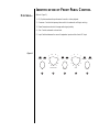
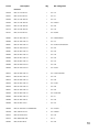
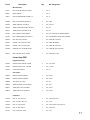
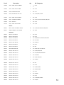
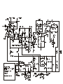
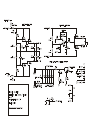
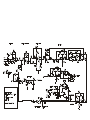
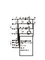
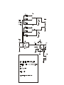
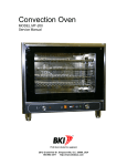
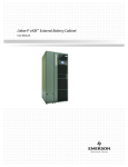
PRELIMINARY
SERVICE MANUAL
HPS 500
POWERED SUBWOOFER
Infinity Systems Incorporated
250 Crossways Park Dr.
Woodbury, New York 11797
- CONTENTS -
SPECIFICATIONS ………….………….….………………………………………..2
SET-UP GUIDE
………………….…………………………………..…………..3
CONTROLS …………………….………….……………………………………….6
OPERATION
………..…..………………………….…………..……………..7
PARTS LIST ………………..………….…………………………………………….9
SCHEMATICS
………..……...…………………………….…………………...16
Infinity HPS-500
500w Powered Sub Amp SPECIFICATIONS
Frequency respose
Drive Unit
22Hz - 120Hz
15" Woofer
Weight
77.2 lbs./35kg
19 3/4 x 19 x 22 7/16" (502 x 483 x 570mm)
Dimensions (H x W x D)
LINE VOLTAGE 120VAC/60Hz
LINE VOLTAGE 230VAC/50Hz
Parameter
Specification
Unit
Amp Section
Type (Class AB, D, other)
AB Bridged
-Load Impedance (speaker)
20 Ohms
Rated Output Power
500 Watts
THD@ Rated Power
0.1 %
THD @ 1 Watt
0.3 %
Polarity
0 deg.
DC Offset
20 mV-DC
Damping factor
>200 DF
Limits
Conditions
--400
1
1
0° ±20
50
--
BASH® Power Supply
Nominal
1 input driven
22k filter
22k filter
In phase at 50Hz in Direct Mode
@ Speaker Outputs
31
±2dB
±2dB
Nominal Freq.
To Rated Power
To Rated Power
Notes
Z-curve required
500w
.250 faston (+)……205 faston (-)
Input Sensitivity
Input Frequency
Line Input
Speaker/Hi Level Input
31 Hz
350 mVrms
8 Vrms
Signal to Noise
SNR-A-Weighted
SNR-unweighted
SNR rel. 1W-unweighted
Residual Noise Floor
Residual Noise Floor
100
70
60
2
1.5
Input Impedance Line Input
Speaker/Hi Level Input
3k ohms
470 ohms
Active Filters
Low Pass (fixed or variable)
Low Pass filter (point or range)
Slope
Q
Normal-Direct Switch
Low Pass filter (point or range)
Slope
Q
Subsonic filter (HPF)
Slope
Q
Video Boost Switch
Boost
Range
Features
Limiter
Line Out Crossover Switch
Phase Switch
Line Output (80Hz HPF-unity gain)
Volume pot Taper (lin/log)
Input Configuration
Line Out: 80/120/160Hz HPF
Slope
Q
dBA
dBr
dBr
mVrms
mVrms(max)
Variable
45-120 Hz
12 dB/Octave
0.707 Damping
yes
-160 (direct),
45-120 (normal) Hz
12 dB/Octave
-Damping
31 Hz
12 dB/Octave
-Damping
yes
-+3 dB
40-80 Hz
90
70
55
3
2
1 input driven
1 input driven
(-26dB below Line In)...1 input driven
relative to rated power
A-Weighting filter
relative to rated power
22k filter
relative to 1W Output
22k filter
Volume @max, using RMS reading DMM/VOM (or A/P)
Volume @max, w/ A/P Swept Bandpass Measurement (Line freq.+ harmonics)
N/A
N/A
Note: Center positon = 100Hz
±2dB
n/a
n/a
functional
±2dB
--±2dB
------
--
log
----
--80/120/160 Hz
6 dB/Octave
0.707 Damping
Power on Delay time
Transients/Pops
ATO Transient
Turn-on Transient
Turn-off Transient
>3 sec.
10 mV-peak
500 mV-peak
500 mV-peak
Efficiency
Stand-by Input Power
Power Cons.@rated power
10 Watts
670 Watts
Protection
Thermal Protection
DC Offset Protection
Line Fuse Rating
yes
yes
6 Amps
functional
functional
functional
functional
functional
functional
>3
AC Power Applied
20
1v-pp
1v-pp
@ Speaker Outputs
@ Speaker Outputs
@ Speaker Outputs
15
N/A
@ nom. line voltage
@ nom. line voltage
functional
functional DC present at Speaker Out leads
functional Type-T or Slo Blo
AC Line cycled from OFF to ON
AC Line cycled from ON to OFF
Decreases gain at 113°C -1.3dB
Relay or crowbar (for driver/fire protection)
External fuse with UL/SEMKO rated holder
2
CONNECTING YOUR SUBWOOFER
If your receiver/processor does not have subwoofer outputs for the left and right channels:
L
+
R
—
—
INPUTS
+
+
B-LINK™
L
+
—
OUTPUTS
R
—
CONNECTING YOUR SUBWOOFER (Continued)
NOTE: Some receivers have a single
subwoofer output (do not confuse this
with a single LFE output as described
below). In that case, it is recommended
that you use a Y connector (not included)
to maximize performance.
If your receiver/processor has subwoofer outputs for the left and right channels:
LOW
LEVEL
IN
LOW
LEVEL
OUT
L
HIGHPASS
OUTPUT
120Hz
160Hz
80Hz
NOTE: In this case, you do not need to
use a Y connector. Simply connect the
LFE output on your receiver/processor
to either the left or right input on
the subwoofer.
R
If you have a Dolby* Digital or DTS® receiver/processor with a low-frequency-effect
(LFE) output:
SUBWOOFER OR
LFE OUTPUT
LOW
LEVEL
OUT
LOW
LEVEL
IN
L
HIGHPASS
OUTPUT
120Hz
160Hz
80Hz
R
If your receiver/amplifier has preamp output jacks and main input jacks for the left and
right channels or you have a separate preamp/processor and power amplifier:
This method of hookup can offer the highest level of performance for your complete loudspeaker
system. Your subwoofer incorporates an adjustable high-pass crossover in addition to a variable
low-pass crossover. When hooked up as shown below, the subwoofer will limit the low-frequency
information that is returned to your receiver/amplifier. Your receiver/amplifier does not need to
waste valuable power reproducing the low frequencies. In addition, since no low-frequency
information is being sent to your main loudspeakers, they are able to reproduce mid and high
frequencies with greater clarity.
LOW
LEVEL
OUT
HIGHPASS
OUTPUT
120Hz
160Hz
80Hz
LOW
LEVEL
IN
L
R
RECEIVER/AMPLIFIER
OR PROCESSOR/AMPLIFIER
PRE
OUT
MAIN
IN
LEFT
RIGHT
LOUDSPEAKER
RIGHT
MAIN SPEAKER
OUTPUT
RIGHT
LEFT
LEFT
LOUDSPEAKER
IDENTIFICATION OF FRONT PANEL CONTROL
CONTROLS...
(Refer to Figure 2.)
1. EQ: Optimizes subwoofer performance for audio or video playback.
2. Crossover: Controls the frequency below which the subwoofer will begin working.
3. Phase: Reverse/normal switch changes audio-signal polarity.
4. Gain: Controls subwoofer volume level.
5. Input: Switches between the normal line/speaker inputs and the direct-LFE input.
Figure 2.
150
AUDIO
50
10
0˚
VIDEO
180˚
100
CROSSOVER
EQ
1
0
NORMAL
GAIN
PHASE
2
DIRECT
3
INPUT
4
5
OPERATION
SET CONTROLS...
1.
Initially set the HPS’s Gain control to the “O” position.
2.
Initially set the HPS’s Crossover control to the 100Hz position.
3.
Plug your HPS’s AC cord into a wall outlet. Do not use the outlets on the back of the receiver.
4.
Turn on your HPS sub by pressing the power button on the center of the front panel.
5.
Turn on your entire audio system and start a CD or movie sound track at a moderate level.
6.
Turn your HPS’s Gain control 4 (Figure 2) up to the “5” position (half way). If no sound
emanates from the subwoofer, check the AC-line cord and input cables. Are the connectors
on the cables making proper contact? Is the AC plug connected to a “live” receptacle? Has
the power button been pressed to the “on” position? (Note: A green indicator on the front
panel will light when the power is on.) Once you have confirmed that the subwoofer is
active, proceed by playing a CD, record or cassette. Use a selection that has ample bass
information.
7.
Set the overall volume control of the preamplifier or stereo to a comfortable level. Adjust
the subwoofer’s Gain control 4 (Figure 2) until you obtain a pleasing blend of bass. Bass
response should not overpower the room but rather be adjusted so there is a harmonious
blend across the entire musical range. Many users have a tendency to set the subwoofer
volume too loud, adhering to the belief that a subwoofer is there to produce lots of bass.
This is not entirely true. A subwoofer is there to enhance bass, extending the response of
the entire system so the bass can be felt as well as heard. However, overall balance must
be maintained or the music will not sound natural. An experienced listener will set the
volume of the subwoofer so its impact on bass response is always there but never obtrusive.
CROSSOVER ADJUSTMENTS…
8.
Crossover Control 2 (Figure 2) – The Low-Pass control determines the highest frequency
at which the subwoofer reproduces sounds. If your main speakers can comfortably reproduce
some low-frequency sounds, set this control to a lower frequency setting, between
50Hz – 100Hz. This will concentrate the subwoofer’s efforts on the ultradeep bass sounds
required by today’s films and music. If you are using smaller bookshelf speakers that do
not extend to the lower bass frequencies, set the low-pass crossover control to a higher
setting, between 120Hz – 150Hz.
PHASE CONTROL...
9.
The Phase Control 3 (Figure 2) determines whether the subwoofer speaker’s piston-like
action moves in and out with the main speakers, 0˚, or opposite the main speakers, 180.̊
Proper phase adjustment depends on several variables such as room size, subwoofer
placement and listener position. Adjust the phase switch to maximize bass output at the
listening position.
10.
The EQ switch, located on the front panel, optimizes the subwoofer's performance for
both movie and music listening. When in the “Video” position, a special EQ circuit is
activated, enhancing low frequencies by approximately 3dB at 32Hz and delivering the
full impact and excitement of today’s movie soundtracks. When in the “Audio” position,
the subwoofer provides the accurate and linear frequency response that is ideal when a
natural tonal balance is desired for music listening.
11.
Remember: every system, room and listener is different. There are not necessarily any right
or wrong settings; any setting you choose will result in excellent performance. Should you
decide to fine-tune your system for optimum performance, be patient and trust your ears.
It will be worth the effort involved to fully “tweak” your system.
POWER ON…
ADJUST GAIN…
12 ◆ HPS-500/1000 – Owner’s Manual
A WORD OF ADVICE
The low-frequency Crossover and Volume controls may be set anywhere within their rotation.
However, it will be a most unusual circumstance if you have to set the Volume control completely
clockwise. This may indicate an unbalanced condition in your system (too much bass), that the
system is in an especially large room, or that speaker placement may be incorrect. Try several
other locations before concluding that the Volume control must be set at maximum.
OVERDRIVE PROTECTION
Automatic limiting circuitry helps prevent overdriving a connected subwoofer by softly clipping
the input signal if it exceeds a predetermined threshold. Depending on the level, you may or
may not hear slight distortion on musical peaks. This protection is completely automatic, with
no user adjustments. However, if you do hear distortion continuously while playing music,
the input signal level (feeding the HPS) may be too high and should be lowered. If this doesn’t
solve the problem, check the connections and that the other components in the audio chain are
operating properly.
A WORD ABOUT TONE CONTROLS
The tone controls on your electronic components (preamplifier, receiver, etc.) should be used
with the utmost discretion. Excessive boost can create severe power demands on your power
amplifier. Maximum bass boost can create a demand for literally hundreds of watts in the bass
region, whereas in the “flat” position, or with the tone controls switched out of the system, your
average listening level may be impressively and realistically loud at fewer than 10 watts. The
remaining power capacity required is on reserve for power peaks on sharp transients and
powerful crescendos.
HPS500 PARTS LIST
AMP ASSEMBLY #333777-001
Power supply PCB
Part #
Description
Qty
Ref. Designator
Integrated Circuits
UA0003
OPAMP, QUAD 14PIN DIL LM324N
1
EA U3
UP0004
PWM, 8PIN DIL UC3842N
1
EA U5
Transistors
QB0002
TRANS, NPN 40V .6A TO92 2N4401
3
EA Q4,Q13,Q14
QB0017
TRANS, NPN 150V 0.6A 2N5551
3
EA Q1,Q8,Q23
QB0018
TRANS, PNP 150V 0.6A 2N5401
3
EA Q7,Q22,Q26
QB0013
TRANS, PNP TIP30B/C TO220
1
EA Q21
QB0019
TRANS, NPN TIP29B/C T0220
1
EA Q19
QB0033
TRANS, NPN 250V 1A TO220 TIP47
1
EA Q3
QM0015
MOSFET, IRF640 TO220AB
2
EA Q9,Q27
Capacitors
CC0020
CAP, CA 470PF 100V 5%
2
EA C3,C73
CC0059
CAP, CA .1UF 100V 20%
3
EA C13,C35,C65
CC0065
CAP, CA 2200P 50V 5%
3
EA C6,C19,C20
CC0072
CAP, CA 100PF 100V 10%
1
EA C74
CC0082
CAP, CA .1UF 50V 20%
4
EA C55,C56,C80,C81
CC0087
CAP, CA .01UF 100V 20%
1
EA C28
CC0021
CAP, C 470PF 1KV 10%
3
EA C2,C9,C11
CC0032
CAP, C 2200PF 600V 10%
1
EA C14
CC0050
CAP, C .1UF 50V 20% .2LS
1
EA C24
CC0078
CAP, C .22UF 50V 10% .2LS
1
EA C17
CC0095
CAP, C 470P 100V 5
2
EA C22,C23
CE0010
CAP, E 22UF 50V 20% 105C
2
EA C4,C79
CC0020
CAP, CA 470PF 100V 5%
1
EA C10
CC0078
CAP, C .22UF 50V 10% .2LS
1
EA C17
CE0121
CAP, E 470UF 200V 20% 30X25
5
EA C30,C31,C32,C33,C34
CF0008
CAP, F 2200PF 100DC 63AC 5%
1
EA C21
CF0146
CAP, F 6.8UF 250V 10% 27MMLS
1
EA C12
Diodes
DS0001
RECT, 100mA 75V SIGNAL 1N4148T
7
EA D2,D5,D6,D7,D12,D24,D25
DZ0002
ZENER, 500mW 12V 5% 1N5242B
3
EA Z1,Z5,Z6
DR0085
RECT, 8A 400V TO220AC MUR860
1
EA D9
DZ0018
ZENER, 2.5-37V SHUNT TL431CLP
1
EA D23
9
Part #
Description
Qty
Ref. Designator
Resistors
RC0006
RES, CF 10K 1/4W 5%
1
EA R17
RC0037
RES, CF 2K0 1/4W 5%
1
EA R3
RC0082
RES, CF 100K 1/2W 5%
1
EA R77
RC0083
RES, CF 100K 1/4W 5%
2
EA R25,R51
RC0091
RES, CF 150K 1/2W 5%
1
EA R94
RC0116
RES, CF 330K 1/4W 5%
1
EA R12
RC0127
RES, CF 30K 1/4W 5%
2
EA R8,R38
RC0273
RES, ZERO OHM 1/4W
1
EA R24
RM0001
RES, MF 1K00 1/4W 1%
4
EA R30,R50,R68,Z4
RM0002
RES, MF 10K0 1/4W 1%
1
EA R71
RM0011
RES, MF 100K 1/4W 1%
6
EA R5,R6,R10,R11,R28,R70
RM0012
RES, MF 100R 1/4W 1%
1
EA R54
RM0031
RES, MF 3K32 1/4W 1%
1
EA R43
RM0034
RES, MF 4K32 1/4W 1%
1
EA R16
RM0035
RES, MF 4K75 1/4W 1%
1
EA R45
RM0043
RES, MF 6K81 1/4W 1%
1
EA R74
RM0065
RES, MF 200R 1/4W 1%
1
EA R49
RM0079
RES, MF 750R 1/4W 1%
2
EA R9,R13
RM0089
RES, MF 2K43 1/4W 1%
1
EA R41
RM0113
RES, MF 20K0 1/4W 1%
4
EA R14,R15,R35,R88
RM0114
RES, MF 22K1 1/4W 1%
1
EA R72
RM0116
RES, MF 25K5 1/4W 1%
1
EA R46
RM0120
RES, MF 30K1 1/4W 1%
2
EA R7,R47
RM0126
RES, MF 47K0 1/4W 1%
1
EA R26
RM0147
RES, MF 16K2 1/4W 1%
1
EA R22
RM0180
RES, MF 4K99 1/4W 1%
3
EA R2,R27,R37
RM0249
RES, MF 28K7 1/4W 1%
1
EA R4
RM0260
RES, MF 1M0 1/4W 1%
1
EA R32
RM0299
RES, MF 2K55 1/4W 1
1
EA R31
RM0336
RES, MF 47R 0.6W 1% FLAMEPROOF
4
EA R18,R39,R89,R90
RM0339
RES, MF 10R 0.6W 1% FLAMEPROOF
2
EA R21,R93
RW0022
RES, WW 0R1 2W 5%
2
EA R40,R92
RX0072
RES, MO 100R 1W 5%
1
EA R19
RC0273
RES, ZERO OHM 1/4W
1
EA L3
RX0080
RES, MO 4R7 2W 5%
1
EA R20
10
Part #
Description
Qty
Ref. Designator
Miscellaneous
540130
IND, CM CHOKE 150UH ELYTONE
1
EA L4
BF0007
BEAD, FERRITE
1
EA L5
JH0074
CNCTR, HEADER 8PIN LOCKING .1C
1
EA J3
KS0021
SURGISTOR, 4R 8A 70J SL154R008
1
EA R23
MM0025
MISC, PC MT SCREW TERM 6-32
2
EA B1,B2
MT0003
TERM, KWIKDISC .25 PCB MT
2
EA CD+,DC+
MT0023
TERM, FASTON MALE PCMT 187X032
1
EA CD-
MT0031
TERM, FASTON .205 MALE PC MT
1
EA DC-
810066
MET, HTSNK CLIP HPS SERIES
6
EA FET CLIPS ON THE POWER BOARD
810068
MET, HTSNK HPS500 PWR SUPPLY
1
EA HEATSINK PLATE FOR THE POWER B
HN0006
NUT, KEP 1/4AF 6-32 ZNP
1
EA USED ON L4 (540130)
HS0004
SCREW, 6-32 1/4 PAN PHIL ZNP
2
EA USED ON MM0025
HS0079
SCREW, 6-32 1.5 NYLON PAN
1
EA USED ON L4 (540130)
HW0030
WASHER, FLAT .375OD #8 NYLON
1
EA USED ON THE L4 (540130)
MS0005
SILPAD, .009" .3C/W TO3P
5
EA USED WITH 5 FETS
MS0014
MISC, CERAMIC PLATE TO-220
1
EA USED WITH 1 FET
Linear Amp PCB
Integrated Circuits
UA0003
OPAMP, QUAD 14PIN DIL LM324N
2
EA U101,U102
UA0009
OPAMP, QUAD 14P DIL TL074/084
2
EA U1,U100
UF0013
FOTO, 6PIN MOC3012
1
EA U4
Transistors
QM0015
MOSFET, IRF640 TO220AB
2
EA Q4,Q8
QM0032
MOSFET, IRF9640 T0220AB
2
EA Q3,Q7
QM0035
JFET, N-CH J111 TO92
1
EA Q9
QB0002
TRANS, NPN 40V .6A TO92 2N4401
1
EA Q101
QB0017
TRANS, NPN 150V 0.6A 2N5551
2
EA Q1,Q5
QB0018
TRANS, PNP 150V 0.6A 2N5401
2
EA Q2,Q6
QB0049
TRANS,
1
EA Q100
TO92 2N3819
Capacitors
CC0059
CAP, CA .1UF 100V 20%
4
EA C52,C54,C57,C58
CC0072
CAP, CA 100PF 100V 10%
2
EA C1,C3
CC0082
CAP, CA .1UF 50V 20%
6
EA C29,C61,C62,C110,C120,C121
CC0098
CAP, CA .047U 50V 10
2
EA C109,C122
CE0127
CAP, E 470UF 35V 10X21
1
EA C127
11
Part #
Description
Qty
Ref. Designator
CF0090
CAP, F .022UF 100V 5% 10MMLS
1
EA C102
CF0094
CAP, F .047UF 100V 5% 10MM
1
EA C122
CE0003
CAP, E 2.2UF 50V 20% 105C
1
EA C111
CE0098
CAP, E 22UF 50V 20% 5X11 .2LS
5
EA C6,C50,C64,C67,C68
CE0106
CAP, E 22UF 35V BP 6X11 .2LS
4
EA C8,C9,C12,C101
CF0035
CAP, F .022UF 100V 5% 5MMLS
1
EA C108
CF0045
CAP, F .1UF 63DC 5% 5MMLS
9
EA C5,C7,C10,C11,C103,C104,C105,C106
CF0099
CAP, F .68U 63V 5
1
EA C100
CF0119
CAP, F .047UF 100V 5% 5MM
2
EA C2,C4
Diodes
DS0001
RECT, 100mA 75V SIGNAL 1N4148T
28
EA D1,D2,D3,D4,D5,D6,D7,D8,D9,D10
DZ0021
ZENER, 500MW 15V 5% 1N5245B
2
EA Z1,Z2
Resistors
RC0001
RES, CF 1K0 1/2W 5%
1
EA R140
RC0004
RES, CF 1M0 1/4W 5%
1
EA R130
RC0006
RES, CF 10K 1/4W 5%
8
EA R39,R60,R121,R122,R123,R124,R146
RC0037
RES, CF 2K0 1/4W 5%
2
EA R127,R131
RC0083
RES, CF 100K 1/4W 5%
2
EA R16,R128
RC0127
RES, CF 30K 1/4W 5%
1
EA R143
RC0197
RES, CF 3K6 1/2W 5%
1
EA R38
RC0273
RES, ZERO OHM 1/4W
5
EA R32,R113,R119,C126,D110
RM0001
RES, MF 1K00 1/4W 1%
4
EA R2,R34,R108,R120
RM0002
RES, MF 10K0 1/4W 1%
5
EA R125,R129,R149,R150,R151
RM0011
RES, MF 100K 1/4W 1%
2
EA R136,R137
RM0024
RES, MF 2K21 1/4W 1%
4
EA R10,R11,R25,R26
RM0029
RES, MF 3K01 1/4W 1%
2
EA R15,R30
RM0031
RES, MF 3K32 1/4W 1%
4
EA R4,R5,R19,R20
RM0039
RES, MF 5K11 1/4W 1%
1
EA R22
RM0041
RES, MF 61K9 1/4W 1%
1
EA R148
RM0043
RES, MF 6K81 1/4W 1%
4
EA R3,R6,R18,R21
RM0071
RES, MF 332R 1/4W 1%
4
EA R8,R9,R23,R24
RM0072
RES, MF 365R 1/4W 1%
1
EA R102
RM0073
RES, MF 392R 1/4W 1%
2
EA R33,R85
RM0075
RES, MF 475R 1/4W 1%
1
EA R120
RM0093
RES, MF 4K53 1/4W 1%
5
EA R7,R58,R61,R62,R63
RM0103
RES, MF 10K5 1/4W 1%
2
EA R31,R84
12
Part #
Description
Qty
Ref. Designator
RM0113
RES, MF 20K0 1/4W 1%
2
EA R35,R36
RM0129
RES, MF 53K6 1/4W 1%
2
EA R14,R29
RM0134
RES, MF 121K 1/4W 1%
1
EA R145
RM0170
RES, MF 59K 1/4W 1%
1
EA R147
RM0180
RES, MF 4K99 1/4W 1%
1
EA R144
RM0183
RES, MF 12K4 1/4W 1%
1
EA R111
RM0191
RES, MF 20K5 1/4W 1%
2
EA R106,R107
RM0198
RES, MF 205K 1/4W 1%
1
EA R114
RM0255
RES, MF 7K15 1/4W 1%
1
EA R101
RM0304
RES, MF 7K87 1/4W 1%
1
EA R37
RM0307
RES, MF 1K15 1/4W 1%
1
EA R109
RM0315
RES, MF 2K67 1/4W 1%
1
EA R100
RM0359
RES, MF 34K8 1/4W 1%
1
EA R110
RM0363
RES, MF 24K3 1/4W 1%
3
EA R105,R115,R117
RM0364
RES, MF 1K91 1/4W 1%
1
EA Z100
RX0074
RES, MO 4K7 1W 5
2
EA R12,R27
RM0260
RES, MF 1M0 1/4W 1%
1
EA C112
RP0056
POT, 5K 8MM HOR TOP ADJ/COVER
2
EA R13,R28
RP0063
POT, A10K SINGLE/BRACKET
1
EA R103
RP0065
POT, B50K DUAL / BRACKET +/- 10%
1
EA R116
RX0097
RES, MO 3K9 2W 5%
1
EA R38
Miscellaneous
JH0028
CNCTR, HEADER 3PIN .100CTR
1
EA SHIELD
JH0063
CNCTR, HEADER 3PIN .1CTR
1
EA J100
JH0074
CNCTR, HEADER 8PIN LOCKING .1C
1
EA J3
KS0019
THERMISTOR, PTH9L04BD22TS2F510
1
EA TH1
MM0025
MISC, PC MT SCREW TERM 6-32
4
EA B1,B2,B3,B4
MT0003
TERM, KWIKDISC .25 PCB MT
2
EA CD-,SPKR-
MT0031
TERM, FASTON .205 MALE PC MT
2
EA SPKR+,CD+
SR0017
SWITCH, 2 POLE 2PDT
3
EA SW3,SW4,SW5
810066
MET, HTSNK CLIP HPS SERIES
4
EA CLIPS FOR FETS
810070
MET, HTSNK LEFT HPS500 FEA/LIN
1
EA LEFT SIDE HEATSINK
810071
MET, HTSNK RIGHT HPS500 F/L
1
EA RIGHT SIDE HEATSINK
HS0004
SCREW, 6-32 1/4 PAN PHIL ZNP
4
EA USED WITH MM0025
AC Power PCB
520025
XFMR, CURRENT YT-7102-1
1
EA L2
540124
IND, CM CHOKE
1
EA L1
13
Part #
Description
Ref. Designator
Qty
CE0004
CAP, E 2.2UF 450V 20% 85C
1
EA C9
CF0057
CAP, FX .22UF 250V 10%
1
EA C5
DB0009
RECT, 6A 400V BRIDGE
1
EA D1
JH0044
CNCTR, HEADER 3PIN .156CTR
1
EA J1
KV0001
VARISTOR, 275V 100J .6W
1
EA Z1
MT0003
TERM, KWIKDISC .25 PCB MT
1
EA DC+
MT0031
TERM, FASTON .205 MALE PC MT
1
EA DC-
RC0004
RES, CF 1M0 1/4W 5%
1
EA R1
SR0009
SWITCH, PUSH TV5
1
EA SW3
Shield board PCB
DL0021
LED, 3MM GREEN
2
EA LED1,LED2
JC0118
CNCTR, 3PIN LED HARNESS 4"
1
EA J1
MZ0026
STANDOFF, 7.5MM LED 2PIN
2
EA TO SUPPORT THE LED
Final assembly
DL0023
LED, REFLECTOR
1
EA TO BE USED ON THE AMP HOUSING
HS0072
SCREW, #4 HI-LOW PAN PHIL ZNP
6
EA USED TO ATTACH THE CABLE TIE A
HS0073
SCREW, #6 HI-LOW PAN PHIL ZNP
12
EA 4PC ON FEATURE LINEAR BOARD
4PC ON CLASS D BOARD
4PC USED WITH MC0003
JC0071
CNCTR, FEM-FEM HARNESS 8PIN 9"
1
EA FROM CLASS D TO FEA/LIN BOARD
JC0114C
CNCTR, 3PIN MALE/3PIN FEM LOCK
1
EA AC CONNECT TO JC0114A ON INPUT
JC0117C
CNCTR, 3PIN FEM/3PIN FEM 47.5"
1
EA CONNECT TO JC0117A ON THE INPU
JC0135
CNCTR, CLASSD PWR CBL 5.75/6.5
1
EA CD+/- FROM CLASS D BD TO FEA/L
JC0136
CNCTR, DC POWER CABLE 4.25"/5"
1
EA DC+/- FROM CLASS D BD TO AC PW
JC0137
CNCTR, SPEAKER CABLE 21"/23"
1
EA ON THE FEA/LIN BOARD
MC0003
CABLE, TIE 40MM W/ METAL RING
4
EA CABLE TIE WITH RING TERMINALS
RP0076
POT, KNOB FOR HPS SERIES
2
EA KNOBS FOR THE POTS
RP0077
POT KNOB FOR HPS SWITCH
3
EA KNOB FOR THE PUSH SWITCH
RP0078
POT KNOB FOR HPS BUTTON
1
EA KNOB FOR THE POWER BUTTON
TS0017
FIBREGLASS, HT210 #2AWG 3"
1
EA SLEEVING FOR JC0137
Hi level Input components
630021
PCB, INPUT HI-LVL HPS SERIES
1
EA
RC0118
RES, CF 15R 1/2W 5%
2
EA R2,R5
RM0085
RES, MF 2K00 1/4W 1%
2
EA R3,R6
CE0106
CAP, E 22UF 35V BP 6X11 .2LS
2
EA C1,C2
500086
XFMR, POWER AUDIO YT-6821
2
EA T1,T2
CF0143
CAP, FY1 4700PF 250V 20
2
EA C3,C4
14
Part #
Description
Ref. Designator
Qty
JC0139
CNCTR, HARNESS HI-LVL 8.5"
1
EA J1/J2
RW0037
RES, WW 470R 5W 5
2
EA R1,R4
Input PCB
630028
PCB, INPUT HPS500/1000
1
EA REVISION
CF0045
CAP, F .1UF 63DC 5% 5MMLS
4
EA C14,C15,C17,C18
CF0128
CAP, F .033UF 100V 5MMLS
2
EA C13,C16
RM0002
RES, MF 10K0 1/4W 1%
2
EA R12,R13
RM0029
RES, MF 3K01 1/4W 1%
2
EA R10,R11
500086
XFMR, POWER AUDIO YT-6821
1
EA T10
CE0106
CAP, E 22UF 35V BP 6X11 .2LS
1
EA C10
CF0143
CAP, FY1 4700PF 250V 20
1
EA C12
JC0052
CNCTR, RCA QUAD JACK
1
EA RCA1
JH0063
CNCTR, HEADER 3PIN .1CTR
2
EA J34,J36
MM0025
MISC, PC MT SCREW TERM 6-32
1
EA W5
SR0022
SWITCH, DPDT TOGGLE C/W CAP PC
1
EA SW1
630031
PCB, INPUT SHIELD HPS500/1K
1
EA
930035
CUP, OUTER PLASTIC HPS250
1
EA OUTER PLASTIC CUP
930039
CUP, INNER PLASTIC HPS500
1
EA INNER PLASTIC CUP
FH0010
FUSE, HOLDER PANEL MT RANGLE
1
EA ON THE INNER CUP
FS0026
FUSE, 4A 250V 1.25X.25 GLASS
1
EA FUSE
HN0001
NUT, KEP 3/16AF 4-40 ZNP
2
EA USED ON THE IEC CONNECT0R
HN0015
NUT, HEX KEP #8-32 ZNP
8
EA USED ON THE BINDING POSTS
HS0041
SCREW, SELF TAP #4 BLK OXIDE
1
EA USED ON THE RCA
HS0055
SCREW, #4-40X1/2 PAN PHIL BLK
2
EA USED ON THE IEC CONNECTOR
HS0065
SCREW, #6-32X1/4 PAN PHIL BLK
1
EA USED ON MM0025
HS0072
SCREW, #4 HI-LOW PAN PHIL ZNP
4
EA TO SECURE THE CUPS AND CABLE TIES
HS0074
SCREW, #4-40X3/4 PAN PHIL ZNP
2
EA BETWEEN SHIELD AND INPUT PCB
JC0076
CNCTR, AC IEC SOCKET .250TAB
1
EA ON THE INNER PLASTIC CUP
JC0086
CNCTR, SINGLE BINDING POST RED
4
EA ON THE INNER PLASTIC CUP
JC0087
CNCTR, SINGLE BINDING POST BLK
4
EA ON THE INNER PLASTIC CUP
JC0114A
CNCTR, 3PIN FEM/2XFEM FASTON
1
EA CONNECT TO MATING HARNESS ON PWR B
JC0117A
CNCTR, 3PIN FEM/3PIN MALE 11"
1
EA CONNECTO TO MATCHING HARNESS
MC0003
CABLE, TIE 40MM W/ METAL RING
2
EA TO SECURE CABLE TIES
MM0027
RUBBER GROMMETS
4
EA 2 ON THE TRANSFORMER
MZ0023
STANDOFF, .5" NYLON LOCKING
1
EA STANDOFF
MZ0028
STANDOFF, 1/2" AL ID.151 #409
1
EA BETWEEN INPUT SHIELD AND INPUT PCB
WI0032
WIRE, POWER CORD SPT2/IEC 8FT
1
EA POWER CORD
15